Transcription
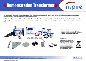
Demonstration TransformerThe Demonstration Transformer, accessories and special power supply have been designed with safety in mind. The coils are constructed to prevent inappropriate andpotentially dangerous configurations which could generate lethal voltages.Limited output voltages are available from the Demonstration Transformer Power Supply and it has special connectors for specific coils - a separate notes for use describesthe power supply in full. Using the demonstration Transformer Power Supply is recommended for all transformer experiments. The range of devices and accessories is shownhere:4 Shrouded sockets4 Maximum voltages are limited by design4 Designed for use in school/college laboratories4 12 month manufacturer's warrantyWEEE directiveThis symbol indicates that theelectronic equipment should notbe disposed of in the normalwaste. It should be recycled inaccordance with the WEEEdirective. This applies to thecoils, leads and power supply,but not to the other parts.Scientific Laboratory Supplies Ltd, Wilford Industrial Estate, Ruddington, Nottingham NG11 7EPT: 0115 982 2022 F: 0115 945 5379 E: sales@science2education.co.uk rV2 : 181111
Demonstration Transformer SetU and I core, base and clamping barCoilsSupplied with the transformer core:300 turn coil600 turn coil900 turn coil1800 turn coil1200 turn coil withcentre-tap (600-0-600)The U-shaped core is secured to the base,and the I-core rests on top, clamped in placeby the white bar and two nuts.100 turn coil (with leads & wings)300 turn coil (with leads & wings) these Mains Substitute Coils are supplied separately.These coils have moulded "wings" which block the fitting of other coils to the core.Induction Accessory Set (supplied separately)Six turn copper coilWith screw clamps to hold a nailfor the nail melting demonstration.NailsSolid and split aluminium ringsSolder troughSteel flat-headed nails 65 x 3 mmor 2½ x 1/8 inch, some with acentral groove making the nailthinner at that point.Two solid and one split for thering-launching demonstration.Effectively a single turn coilin the form of a circular trough.Approximately 300 mm of solderis formed into a 50 mm diametercircle to lie in the trough.Scientific Laboratory Supplies Ltd, Wilford Industrial Estate, Ruddington, Nottingham NG11 7EPT: 0115 982 2022 F: 0115 945 5379 E: sales@science2education.co.uk rV2 : 181111
Motor Accessory Set (supplied separately)VerticalSupportRodPair of AluminiumQuadrant PlatesAluminiumMotor DiscPole PiecesNailsClamping screwsand Pivot rodDemonstration Transformer Power Supply (supplied separately)The power supply has fixed outputs of:25 V ac at up to 10 A for use with the 100 and 300 turn Mains Substitute Coils2 V and 4 V ac at up to 5 A4 V and 8 V dc at up to 5 AOutputs are individually protected by independent thermal trips.In the event of short circuit or overload, output can be restored byremoving the problem and pressing the RESET button.It might be necessary to wait a short time, to allow the thermal trip to cool.800 turn Mains Coil (supplied separately)A traditional 800 turn Mains Coil is available as an alternative, to power the induction experiments and the shaded pole motor.Scientific Laboratory Supplies Ltd, Wilford Industrial Estate, Ruddington, Nottingham NG11 7EPT: 0115 982 2022 F: 0115 945 5379 E: sales@science2education.co.uk rV2 : 181111
Typical experimentsSyllabus referencesThe transformer core and coils can be used to demonstrate the principles of transformers:dependence of induced voltages on the coil corethe relationship between turns ratios, primary and secondary voltagesinvestigation of efficiency.AQA 3.7.5.4 Electromagnetic induction - induced emf andflux linkage.With the induction accessories the set provides classic demonstrations of:nail melting, induction furnace and ring launching.Using the motor accessories, the set provides demonstrations of:shaded pole motor, eddy current braking.AQA 3.7.5.6 Operation of a transformer - transformer equation,efficiency, eddy currents and causes of inefficiency.Edexcel 121-125 Factors affecting the emf induced in a coil,flux linkage.OCR 6.3.3 Electromagnetism - ideal transformer, techniques andprocedures used to investigate transformers.In all the experiments and demonstrations, the Demonstration Transformer Power Supplyhas been used. This ensures that combinations of the coils supplied cannot create asecondary voltage greater than 25 V acThe five coils can be used in any configuration of primary and secondary on thetransformer core.Some experiments will require a rheostat and diodes.CAUTION: if you choose not to use the Demonstration Transformer Power Supplythen you must use a power supply whose output can be limited and locked.Setting the limit at 2 V or 4 V ac is suitable for some experiments.Limiting the dc output to 4 V or 8 V is suitable for other experiments.Recommended lockable power supplies are:PowerPro Prime, PowerPro Regulated or PowerPro Variable.For the induction experiments and the shaded pole motor, you have two options:use the Demonstration Transformer PSU plus the100 turn or 300 turn Mains Substitute CoilsORuse the traditional 800 turn Mains Coil.Scientific Laboratory Supplies Ltd, Wilford Industrial Estate, Ruddington, Nottingham NG11 7EPT: 0115 982 2022 F: 0115 945 5379 E: sales@science2education.co.uk rV2 : 181111The "wings" on the 100 and 300 turn Mains Substitute Coils block the fittingof other coils onto the core, but allow the Induction Accessories to be used.
Electromagnetic inductionConnect a galvanometer (or centre zero voltmeter) to the 1800 turn coil. Observe the meter while a bar magnet is moved in and out of the coil.Move the magnet slowly, then quickly.With a datalogger and voltage sensor, you can capture the induced voltage when the magnet is dropped through the coil.Discuss and explain the shape of the graph produced.These simple observations are the basis for Faraday's and Lenz's laws of electromagnetism.Dependence of induced voltage on coil coreWhen a dc voltage is applied to a coil, the current flow generates a magnetic field. The coil becomes an electromagnet.This can be tested by applying 4 V dc to the 300 turn coil and bringing iron and steel objects close to it.When an ac voltage is applied to the same coil, the alternating current generates an alternating magnetic field or flux, changing at 50 Hz .Place the 600 turn coil on top of the 300 turn coil. Connect 4 V ac to the 300 turn coil.Use an ac voltmeter to check the voltage applied to the 300 turn coil and the induced voltage in the 600 turn coil.Take the I-core from the transformer and lower it into the two coils. What happens to the induced voltage?Fit the two coils to the transformer U-core and clamp the I-core on top. Check the voltages now.The core assists in the transfer of the alternating magnetic flux between the two coils. The core increases the flux linkage.Turns ratiosUsing the arrangement shown, with coils mounted on the full core,investigate the relationship between the ratio of turns in the twocoils and the ratio of the voltage input to the PRIMARY coil to theoutput from the SECONDARY coil.You have coils with: 300, 600, 900 and 1800 turns, and a centretapped 1200 turn coil with a centre tap, which is effectively two 600turn coils; these can be used individually or as a single 1200 turncoil.You can use the coils in any combination on the core, to exploreturns ratios and the resulting voltages. When the number of turns inthe secondary coil is greater than the number of turns in theprimary coil, the transformer can be described as a "step up"transformer. If the ratio is reversed, then it is a "step down"transformer.Scientific Laboratory Supplies Ltd, Wilford Industrial Estate, Ruddington, Nottingham NG11 7EPT: 0115 982 2022 F: 0115 945 5379 E: sales@science2education.co.uk rV2 : 181111PrimarycoilSecondarycoil
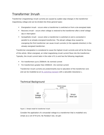
Investigation of efficiencyIn an ideal transformer, the transformer equation applies:NsNp VsVpN is the number of turns, V is the ac voltage, s and p refer to the secondary and primary coils.When the Demonstration Transformer secondary voltages are measured with an ac voltmeter or multimeter, the meter draws very little current from the transformer.The transformer has "no load". In this situation, the transformer equation describes the behaviour of the transformer quite closely.With an input of 2 V ac to the 300 turn primary coil, the 900 turn secondary coil should give an output of 6 V ac. Check this with an ac voltmeter.Connect a 6 V 1 W lamp to the secondary coil. Does it light? Check the secondary voltage again.With an input of 4 V ac to the 300 turn primary coil, the 900 turn secondary coil should give an output of 12 V ac. Check this with an ac voltmeter.Connect a 12 V 2 W lamp to the secondary coil. Does it light? Check the secondary voltage again. Try the 6 V 1 W lamp.When we try to draw current from the secondary coil, the voltage collapses and we have difficulty lighting a low-voltage lamp.This is because the Demonstration Transformer is not an ideal transformer. It is inefficient for a number of reasons.The primary and secondary coils are separated by some distance. The core does not perfectly link the magnetic flux from the primary to the secondary - there are losses.Use a multimeter on the ohms range, to measure the resistance of the coils (after disconnecting them from the power supply and lamp). Whenever a current flows through aresistance, heat is generated and there is a voltage drop.Measuring the efficiency of the Demonstration TransformerYou will need:a rheostat approximately 100 ohmstwo meters, to measure ac voltage and ac current at the same time(four meters would be ideal, allowing you to measure primary andsecondary voltage and current at the same time, as shown).The rheostat controls the current drawn from the secondary coil. It should be set initially togive the maximum resistance, and therefore draw minimum current.With 4 V ac applied to the primary coil, the secondary output should initially be closeto 8 V ac.Create a table of primary voltage (Vp) and current (Ip), secondary voltage (Vs) and current(Is), with a spare column to the right, labelled "efficiency".Reduce the resistance, increasing the load current, by moving the rheostat slider. Entervalues in your table, for a range of settings of the rheostat. Use the efficiency formula tocalculate the transformer's efficiency for each set of values.How does the efficiency vary, and why?Scientific Laboratory Supplies Ltd, Wilford Industrial Estate, Ruddington, Nottingham NG11 7EPT: 0115 982 2022 F: 0115 945 5379 E: sales@science2education.co.uk rV2 : 181111PrimarySecondaryA4 V acA300 t600 tRheostatefficiency Is VsIp VpVV
Determination of coil inductanceThis experiment requires:the 300 turn coil and the I-corea 22 μF (microfarad) capacitora signal generator, e.g. PowerPro Signal Generatoran oscilloscopesix 4 mm plug leads and two crocodile clipsConnect the low impedance output of the signal generator to the coil. Set the signalgenerator to 50 Hz.Connect the oscilloscope to the coil (stack the 4 mm plugs) to observe the waveform.Adjust the signal generator amplitude to show 2 V peak to peak on the oscilloscope.oscilloscopesignal generatorcoil300 tlowimpedanceoutput22 μFwire colours areonly shown forclaritycapacitorSteadily increase the frequency and observe the displayedamplitude on the oscilloscope.How does the coil affect the amplitude as the frequency increases?A resistor has resistance, i.e. it limits the current flowing through it.The unit of resistance is the ohm, symbol Ω.Plug two extra leads to the coil, with crocodile clips on the other ends.Connect the 22 μF capacitor to the crocodile clips. It is in parallel with the coil.A coil, with or without a core, has inductance.The unit of inductance is the henry, symbol H.This arrangement is used as a tuned circuit in some applications.Now observe the displayed amplitude on the oscilloscope as the frequency is changed.Try the range 100 Hz to 1.1 kHzInductance is analogous to resistance, it limits the current flowingthrough the coil. A coil with a core has a greater inductance.You should see that the amplitude varies, with a maximum at a particular frequency.This is the resonant frequency for this tuned circuit.Make a note of the frequency.The inductance value can be calculated, as shown in the panel to the right.Lower the I-core of the transformer into the coil and find the new resonant frequency.Recalculate the inductance.Scientific Laboratory Supplies Ltd, Wilford Industrial Estate, Ruddington, Nottingham NG11 7EPT: 0115 982 2022 F: 0115 945 5379 E: sales@science2education.co.uk rV2 : 181111This formula can be used to calculate the inductance, using the datafrom the experiment.f is the resonant frequency in HzC is the capacitance in farad, Fin this experiment C 22 x 10-6 FTypical inductance for this coil is in the range 1 to 5 mH (millihenry).
Simulating a moving-iron meterYou will need:the Demonstration Transformer Power supplythe 600 turn coiltwo plastic straws - flexible ones are ideala rheostatsome blu-tacktwo pins - dressmakersthree 4 mm plug leadstwo round nails approx 75 x 3 mm (3 x 1/8 inch) - remove the head from one nailTrim the two straws so they fit over the headless nail and bend them as shown.The gap between the verticals should be about 80 mm.Push the two pins through the straws at right angles, 45 mm above the nail.Use some blu-tack to stick the other nail into the corner of the 600 turn coil.Straighten one of the straws to fit it through the coil, then bend it to a right angle again.Place the coil on its side and suspend the straw, nail and pins arrangement so that the two nails are close together.Add two small pieces of blu-tack on top of the coil, to prevent the pins from sliding out of position.Check that the straws and suspended nail can pivot freely on the pins.Connect the rheostat in series with the coil, and to the 4 V ac output of the power supply.Set the rheostat initially to give maximum resistance.Switch on the power supply and observe the straw "pointers" as the rheostat slider is movedtowards minimum resistance.Switch off and return the rheostat to maximum resistance.Repeat the experiment using 4 V dc.Why do the nails move in this way? Is their behaviour the same for ac and dc? Explain why.This simulation is based on an experiment from Nuffield Physics.Scientific Laboratory Supplies Ltd, Wilford Industrial Estate, Ruddington, Nottingham NG11 7EPT: 0115 982 2022 F: 0115 945 5379 E: sales@science2education.co.uk rV2 : 18111180 mm45 mm
RectificationTransformers convert one ac voltage to a lower or higher ac voltage, depending on the turns ratio. This has many applications, some of which are illustrated in these notes.Many devices must have dc current for them to operate correctly. The conversion of ac to dc is called rectification.Half wave rectificationUsing the Demonstration Transformer Power Supply, the full transformer core, the 300 and 600 turn coils, a suitable diode and an oscilloscope, set up the circuit.A 1N 4001 diode is recommended.Sketch the waveform produced with the diode connected as shown,then remove the diode and connect the red wire from thecoil directly to the oscilloscope.It is easy to see why this is called half-wave rectification.Only the positive half of the ac wave is getting throughthe diode. This is not very efficient because half of theenergy input to the transformer is wasted.primaryoscilloscopesecondarydiode4 V ac300 t600 tFull wave rectificationReplace the 600 turn coil with the 1200 turn centre-tapped coil.Connect the coil centre tap to the oscilloscope ground socket.oscilloscopeConnect a second diode as shown, note that both diodes areconnected to the same socket on the oscilloscope.primarysecondaryThere are now two 600 turn coils, each connected via a diodeto the oscilloscope.diodeSketch the waveform produced.The diodes allow positive half waves from each coil in turn topass to the oscilloscope, giving a more consistent average dcvoltage.600 t4 V ac300 tIn both experiments above, you can measure the dc voltage atthe oscilloscope, using a standard dc voltmeter. The ac input tothe transformer has been converted to a dc voltage, with a regularvariation at 100 Hz.Scientific Laboratory Supplies Ltd, Wilford Industrial Estate, Ruddington, Nottingham NG11 7EPT: 0115 982 2022 F: 0115 945 5379 E: sales@science2education.co.uk rV2 : 181111600 tdiodeboth red wiresconnect to theoscilloscopeinput
Nail meltingFor this demonstration, you will need:the complete transformer corethe 100 turn Mains Substitute Coil and Transformer Power Supplythe 6 turn copper coil with clamps to hold a naila heat mat and a pair of tongsStand the transformer core on a heatproof bench mat.Fit the 100 turn coil and the 6 turn copper coil to the core.Connect the 100 turn coil to the 25 V ac terminals of the power supply.Loosen the clamping screws of the 6 turn coil and fit a nail through theholes. Gently press the handles of the coil together while the clampingscrews are tightened. This puts the nail under slight tension.Switch on the power supply and observe the nail.When the nail has melted, switch off and allow the coil and nail to cool.Loosen the clamping screws and use tongs to remove the nail.Why does the nail melt? Why does the 6 turn copper coil NOT melt?Estimate the voltage applied to the nail and, using the formula shown,estimate the current flowing in the nail.Ns secondary turns Np primary turnsVs secondary voltage Vp primary voltageIp primary currentIs secondary currentRepeat the experiment using a nail with a groove near the middle.Explain any differences you notice.Alternative method, using the 800 turn Mains CoilThe 800 turn Mains Coil can be used instead of the 100 turn substitute coil andTransformer Power Supply. The method above is otherwise the same.Similarly, the 800 turn Mains Coil can be used in the Thomson's Ring and InductionFurnace demonstrations on the next page.Scientific Laboratory Supplies Ltd, Wilford Industrial Estate, Ruddington, Nottingham NG11 7EPT: 0115 982 2022 F: 0115 945 5379 E: sales@science2education.co.uk rV2 : 181111
Thomson's jumping ringsYou will need the:Demonstration Transformer Power Supply and transformer core100 turn Mains Substitute Coil3 aluminium rings, one with a cutFit the coil to the U-core and stand the I-core on end, on top of the core that isinside the coil. Connect the coil to the 25V ac output of the transformer.Lower one of the uncut aluminium rings over the core and rest it on the top of the coil.CAUTION: keep the space above the coil and core clear of people and hands!Switch on. Switch off.Repeat the experiment but lower BOTH aluminium rings onto the coil.Explain the difference you observed.Repeat the experiment with the cut ring. How does this support your explanation?If you have access to liquid nitrogen, try cooling one of the aluminium rings thenrepeat the experiment. Explain the observed difference in behaviour.Induction furnace - melting solderUsing the Demonstration Transformer Power Supply, with the 100 turn Mains SubstituteCoil, the full core and the solder trough, connect the coil to the 25V ac output.Stand the transformer core on a heat proof bench mat.Before you fit the solder trough, wrap a 50 cm length of solder wire into a circular coilabout 5 cm in diameter and press it into the solder trough.Fit the I-core and clamp it in place.Switch on and observe the solder. When it has melted, switch off.The core can be unclamped and the solder trough can be lifted off carefully.Pour the molten solder onto the heat proof mat.Allow the trough and solder to cool.The solder trough is effectively a single turn coil. How does this explain the heating effect?Scientific Laboratory Supplies Ltd, Wilford Industrial Estate, Ruddington, Nottingham NG11 7EPT: 0115 982 2022 F: 0115 945 5379 E: sales@science2education.co.uk rV2 : 181111
Experiments with the Motor AccessoriesShaded pole induction motorThis experiment uses the 300 turn Mains Substitute Coil connected to the 25 V ac output of theDemonstration Transformer Power Supply.The transformer core is adapted, using two pole pieces, a vertical support rod and the pivot rod.The aluminium motor disc and quadrant plate (plain, not slotted) are also required.Fit the 300 turn Mains Substitute Coil to the left side of the transformer core.Using the long knurled head screws, attach the two pole pieces to the tops of the U-core.Make sure the left hand pole piece has a hole in its upper surface, into which the vertical supportcan be fitted.Fit the pivot rod through the lower hole in the vertical support and secure the aluminium motor discto the end of the pivot. Fit the vertical support into the hole in the pole piece.Adjust the clamping screws so the motor disc is midway between the pole pieces and free to spin.Connect the coil to the 25 V ac output and switch on the power supply.Hold the quadrant plate by the narrow point and move it into the gap between the motor disc andthe pole piece, as shown. The quadrant plate should just cover or "shade" the pole piece.Be careful not to obstruct the motor disc.If necessary, flick the motor disc to start it revolving.Try shading the opposite pole. What is the effect of this?Scientific Laboratory Supplies Ltd, Wilford Industrial Estate, Ruddington, Nottingham NG11 7EPT: 0115 982 2022 F: 0115 945 5379 E: sales@science2education.co.uk rV2 : 181111
Eddy current brakingThis experiment uses the 300 and 600 turn coils connected in series tothe 8 V dc output of the Demonstration Transformer Power Supply.The transformer is adapted using the two pole pieces, vertical support rod, pivot rod,and the plain and slotted quadrant plates.Fit the 300 turn and 600 turn coils to the transformer core.Using the long knurled head screws, attach the two pole pieces to the topsof the U-core.Make sure the left hand pole piece has a hole in its upper surface, into whichthe vertical support can be fitted. Fit the pivot rod through the upper hole in thevertical support and secure the plain aluminium quadrant to the end of the pivot.Fit the vertical support into the hole in the pole piece.Adjust the clamping screws so the quadrant is midway between the pole piecesand free to swing through the gap.Connect the coils in series, as shown.Move the quadrant out of the gap, then let it swing.Switch on the power supply. Move the quadrant out of the gap and let it swing again.What happens and why? Remember that aluminium not a magnetic material.Magnetic fields induce eddy currents in aluminium and other metals.Replace the plain quadrant with the slotted quadrant.Repeat the experiment above. Explain the difference in behaviour.Scientific Laboratory Supplies Ltd, Wilford Industrial Estate, Ruddington, Nottingham NG11 7EPT: 0115 982 2022 F: 0115 945 5379 E: sales@science2education.co.uk rV2 : 181111
In an ideal transformer, the transformer equation applies: N is the number of turns, V is the ac voltage, s and p refer to the secondary and primary coils. When the Demonstration Transformer secondary voltages are measured with an ac voltmeter or multimeter, the meter draws v

