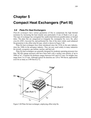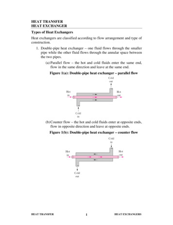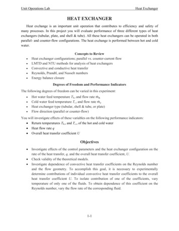
Transcription
CHAPTER 52HEAT EXCHANGERS,VAPORIZERS, CONDENSERSJoseph W. PalenHeat Transfer Research, Inc.College Station, Texas52.152.252.352.1HEAT EXCHANGER TYPESAND CONSTRUCTION52.1.1 Shell and Tube HeatExchangers52.1.2 Plate-Type HeatExchangers52.1.3 Spiral Plate HeatExchangers52. 1 .4 Air-Cooled HeatExchangers52.1.5 Compact Heat Exchangers52.1.6 Boiler Feedwater Heaters52.1.7 Recuperators andRegeneratorsESTIMATION OF SIZE ANDCOST52.2.1 Basic Equations forRequired Surface52.2.2 Mean TemperatureDifference52.2.3 Overall Heat-TransferCoefficient52.2.4 Pressure DropRATINGMETHODS52.3.1 Shell and TubeSingle-Phase Exchangers52.3.2 Shell and Tube Condensers52.3.3 Shell and Tube Reboilersand Vaporizers52.3.4160752.3.5Air-Cooled HeatExchangersOther 1613161416151615161616161616161952.5COMMON OPERATIONALPROBLEMS52.4.1 Fouling52.4.2 Vibration52.4.3 Flow Maldistribution52.4.4 Temperature Pinch52.4.5 Critical Heat Flux inVaporizers52.4.6 Instability52.4.7 Inadequate Venting,Drainage, or BlowdownUSE OF COMPUTERS INTHERMAL DESIGN OFPROCESS HEATEXCHANGERS52.5.1 Introduction52.5.2 Incrementation52.5.3 Main Convergence Loops52.5.4 Rating, Design, orSimulation52.5.5 Program Quality andSelection52.5.6 Determining andOrganizing Input 311632163316331622HEAT EXCHANGER TYPES AND CONSTRUCTIONHeat exchangers permit exchange of energy from one fluid to another, usually without permittingphysical contact between the fluids. The following configurations are commonly used in the powerand process industries.52.1.1Shell and Tube Heat ExchangersShell and tube heat exchangers normally consist of a bundle of tubes fastened into holes, drilled inmetal plates called tubesheets. The tubes may be rolled into grooves in the tubesheet, welded to thetubesheet, or both to ensure against leakage. When possible, U-tubes are used, requiring only oneMechanical Engineers' Handbook, 2nd ed., Edited by Myer Kutz.ISBN 0-471-13007-9 1998 John Wiley & Sons, Inc.
Fig. 52.1 Schematic illustration of shell and tube heat exchanger construction.tubesheet. The tube bundle is placed inside a large pipe called a shell, see Fig. 52.1. Heat is exchangedbetween a fluid flowing inside the tubes and a fluid flowing outside the tubes in the shell.When the tubeside heat-transfer coefficient is as high as three times the shellside heat-transfercoefficient, it may be advantageous to use low integral finned tubes. These tubes can have outsideheat-transfer coefficients as high as plain tubes, or even higher, but increase the outside heat-transferarea by a factor of about 2.5-4. For design methods using finned tubes, see Ref. 11 for single-phaseheat exchangers and Ref. 14 for condensers. Details of construction practices are described bySaunders.58The Tubular Exchanger Manufacturers Association (TEMA) provides a manual of standards forconstruction of shell and tube heat exchangers,1 which contains designations for various types ofshell and tube heat exchanger configurations. The most common types are summarized below.E-TypeThe E-type shell and tube heat exchanger, illustrated in Figs. 52.2a and 52.2Z?, is the workhorse ofthe process industries, providing economical rugged construction and a wide range of capabilities.Baffles support the tubes and increase shellside velocity to improve heat transfer. More than onepass is usually provided for tubeside flow to increase the velocity, Fig. 52.2a. However, for somecases, notably vertical thermosiphon vaporizers, a single tubepass is used, as shown in Fig. 52.2/?.Fig. 52.2TEMA E-type shell: (a) horizontal multitubepass; (b) vertical single tubepass.
Fig. 52.3 TEMA F-type shell.The E-type shell is usually the first choice of shell types because of lowest cost, but sometimesrequires more than the allowable pressure drop, or produces a temperature "pinch" (see Section52.4.4), so other, more complicated types are used.F-Type ShellIf the exit temperature of the cold fluid is greater than the exit temperature of the hot fluid, atemperature cross is said to exist. A slight temperature cross can be tolerated in a multitubepass Etype shell (see below), but if the cross is appreciable, either units in series or complete countercurrentflow is required. A solution sometimes used is the F-type or two-pass shell, as shown in Fig. 52.3.The F-type shell has a number of potential disadvantages, such as thermal and fluid leakagearound the longitudinal baffle and high pressure drop, but it can be effective in some cases if welldesigned.J-TypeWhen an E-type shell cannot be used because of high pressure drop, a J-type or divided flow exchanger, shown in Fig. 52.4, is considered. Since the flow is divided and the flow length is also cutin half, the shellside pressure drop is only about one-eighth to one-fifth that of an E-type shell ofthe same dimensions.X-TypeWhen a J-type shell would still produce too high a pressure drop, an X-type shell, shown in Fig.52.5, may be used. This type is especially applicable for vacuum condensers, and can be equippedwith integral finned tubes to counteract the effect of low shellside velocity on heat transfer. It isusually necessary to provide a flow distribution device under the inlet nozzle.G-TypeThis shell type, shown in Fig. 52.6, is sometimes used for horizontal thermosiphon shellside vaporizers. The horizontal baffle is used especially for boiling range mixtures and provides better flowdistribution than would be the case with the X-type shell. The G-type shell also permits a largertemperature cross than the E-type shell with about the same pressure drop.H-TypeIf a G-type is being considered but pressure drop would be too high, an H-type may be used. Thisconfiguration is essentially just two G-types in parallel, as shown in Fig. 52.7.Fig. 52.4 TEMA J-type shell.
Fig. 52.5TEMA X-type shell.K-TypeThis type is used exclusively for kettle reboilers and vaporizers, and is characterized by the oversizedshell intended to separate vapor and liquid phases, Fig. 52.8. Shell-sizing relationships are given inRef. 25. Usually, the shell diameter is about 1.6-2.0 times the bundle diameter. Design shouldconsider amount of acceptable entrainment, height required for flow over the weir, and minimumclearance in case of foaming.Baffle TypesBaffles are used to increase velocity of the fluid flowing outside the tubes ("shellside" fluid) and tosupport the tubes. Higher velocities have the advantage of increasing heat transfer and decreasingfouling (material deposit on the tubes), but have the disadvantage of increasing pressure drop (moreenergy consumption per unit of fluid flow). The amount of pressure drop on the shellside is a functionof baffle spacing, baffle cut, and baffle type.Baffle types commonly used are shown in Fig. 52.9, with pressure drop decreasing from Fig.52.9a to Fig. 52.9c.Baffle spacing is increased when it is necessary to decrease pressure drop. A limit must beimposed to prevent tube sagging or flow-induced tube vibration. Recommendations for maximumbaffle spacing are given in Ref. 1. Tube vibration is discussed in more detail in Section 52.4.2. Whenthe maximum spacing still produces too much pressure drop, a baffle type is considered that producesless cross flow and more longitudinal flow, for example, double segmental instead of segmental.Minimum pressure drop is obtained if baffles are replaced by rod-type tube supports.5252.1.2Plate-Type Heat ExchangersComposed of a series of corrugated or embossed plates clamped between a stationary and a movablesupport plate, these exchangers were originally used in the food-processing industry. They have theadvantages of low fouling rates, easy cleaning, and generally high heat-transfer coefficients, and arebecoming more frequently used in the chemical process and power industries. They have the disadvantage that available gaskets for the plates are not compatible with all combinations of pressure,temperature, and chemical composition. Suitability for specific applications must be checked. Themaximum operating pressure is usually considered to be about 1.5 MPa (220 psia).3 However, weldedplate versions are now available for much higher pressures. A typical plate heat exchanger is shownin Fig. 52.10.52.1.3Spiral Plate Heat ExchangersThese exchangers are also becoming more widely used, despite limitations on maximum size andmaximum operating pressure. They are made by wrapping two parallel metal plates, separated byFig. 52.6 TEMA G-type shell.
Fig. 52.7 TEMA H-type shell.spacers, into a spiral to form two concentric spiral passages. A schematic example is shown in Fig.52.11.Spiral plate heat exchangers can provide completely countercurrent flow, permitting temperaturecrosses and close approaches, while maintaining high velocity and high heat-transfer coefficients.Since all flow for each fluid is in a single channel, the channel tends to be flushed of particles bythe flow, and the exchanger can handle sludges and slurries more effectively than can shell and tubeheat exchangers. The most common uses are for difficult-to-handle fluids with no phase change.However, the low-pressure-drop characteristics are beginning to promote some use in two-phase flowas condensers and reboilers. For this purpose the two-phase fluid normally flows axially in a singlepass rather than spirally.52.1.4 Air-Cooled Heat ExchangersIt is sometimes economical to condense or cool hot streams inside tubes by blowing air across thetubes rather than using water or other cooling liquid. They usually consist of a horizontal bank offinned tubes with a fan at the bottom (forced draft) or top (induced draft) of the bank, as illustratedschematically in Fig. 52.12.Tubes in air-cooled heat exchangers (Fig. 52.12) are often 1 in. (25.4 mm) in outside diameterwith 5Xs in. (15.9 mm) high annular fins, 0.4-0.5 mm thick. The fins are usually aluminum and maybe attached in a number of ways, ranging from tension wrapped to integrally extruded (requiring asteel or alloy insert), depending on the severity of service. Tension wrapped fins have an uppertemperature limit ( 300 F) above which the fin may no longer be in good contact with the tube,greatly decreasing the heat-transfer effectiveness. Various types of fins and attachments are illustratedin Fig. 52.13.A more detailed description of air-cooled heat exchanger geometries is given Refs. 2 and 3.52.1.5 Compact Heat ExchangersThe term compact heat exchanger normally refers to one of the many types of plate fin exchangersused extensively in the aerospace and cryogenics industries. The fluids flow alternately betweenparallel plates separated by corrugated metal strips that act as fins and that may be perforated orinterrupted to increase turbulence. Although relatively expensive to construct, these units pack a verylarge amount of heat-transfer surface into a small volume, and are therefore used when exchangervolume or weight must be minimized. A detailed description with design methods is given inRef. 4.Fig. 52.8TEMA K-type shell.
Fig. 52.9Fig. 52.10Baffle types.Typical plate-type heat exchanger.
Fig. 52.11 Spiral plate heat exchanger.52.1.6Boiler Feedwater HeatersExchangers to preheat feedwater to power plant boilers are essentially of the shell and tube type buthave some special features, as described in Ref. 5. The steam that is used for preheating the feedwaterenters the exchanger superheated, is condensed, and leaves as subcooled condensate. More effectiveheat transfer is achieved by providing three zones on the shellside: desuperheating, condensing, andsubcooling. A description of the design requirements of this type of exchanger is given in Ref. 5.52.1.7Recuperators and RegeneratorsThese heat exchangers are used typically to conserve heat from furnace off-gas by exchanging itagainst the inlet air to the furnace. A recuperator does this in the same manner as any other heatexchanger except the construction may be different to comply with requirements for low pressuredrop and handling of the high-temperature, often dirty, off-gas stream.The regenerator is a transient batch-type exchanger in which packed beds are alternately switchedfrom the hot stream to the cold stream. A description of the operating characteristics and design ofrecuperators and regenerators is given in Refs. 6 and 59.52.2ESTIMATION OF SIZE AND COSTIn determining the overall cost of a proposed process plant or power plant, the cost of heat exchangersis of significant importance. Since cost is roughly proportional to the amount of heat-transfer surfacerequired, some method of obtaining an estimate of performance is necessary, which can then betranslated into required surface. The term "surface" refers to the total area across which the heat istransferred. For example, with shell and tube heat exchangers "surface" is the tube outside circumference times the tube length times the total number of tubes. Well-known basic equations taken fromNewton's law of cooling relate the required surface to the available temperature difference and therequired heat duty.Fig. 52.12 Air-cooled heat exchangers.
Fig. 52.13 Typical finned tube and attachments.52.2.1 Basic Equations for Required SurfaceThe following well-known equation is used (equation terms are defined in the Nomenclature):A ldrufB(52 !)-The required duty (Q) is related to the energy change of the fluids:(a) Sensible Heat TransferQ W,Cpl(T2 - T1)(52.2a) W2C t1 - t2)(52.2b)Q WX(52.3)(b) Latent Heat Transferwhere W flow rate of boiling or condensing fluidA latent heat of respective fluidThe mean temperature difference (MTD) and the overall heat transfer coefficient (U0) in Eq. (52.1)are discussed in Sections 52.2.2 and 52.2.3, respectively. Once the required surface, or area, (A0) isobtained, heat exchanger cost can be estimated. A comprehensive discussion on cost estimation forseveral types of exchangers is given in Ref. 7. Cost charts for small- to medium-sized shell and tubeexchangers, developed in 1982, are given in Ref. 8.
52.2.2 Mean Temperature DifferenceThe mean temperature difference (MTD) in Eq. (52.1) is given by the equationMTD l "Jf\n(TA/TB)(52.4)Tt T1- t2(52.5)T8-T2- I1(52.6)whereThe temperatures (T1, T2, T1, t2) are illustrated for the base case of countercurrent flow in Fig. 52.14.The factor F in Eq. (52.4) is the multitubepass correction factor. It accounts for the fact that heatexchangers with more than one tubepass can have some portions in concurrent flow or cross flow,which produce less effective heat transfer than countercurrent flow. Therefore, the factor F is lessthan 1.0 for multitubepass exchangers, except for the special case of isothermal boiling or condensingstreams for which F is always 1.0. Charts for calculating F are available in most heat-transfer textbooks. A comprehensive compilation for various types of exchangers is given by Taborek.9In a properly designed heat exchanger, it is unusual for F to be less than 0.7, and if there is notemperature cross (T2 t2), F will be 0.8 or greater. As a first approximation for preliminary sizingand cost estimation, F may be taken as 0.85 for multitubepass exchangers with temperature changeof both streams and 1.0 for other cases.52.2.3 Overall Heat-Transfer CoefficientThe factor (U0) in Eq. (52.1) is the overall heat-transfer coefficient. It may be calculated by proceduresdescribed in Section 52.3, and is the reciprocal of the sum of all heat-transfer resistances, as shownin the equationU0 ll(Rho Rfo Rw Rhi Rf)(52.7)where**. I/*.(52.8)Rhl (AJA1H1)(52.9)RV ATTkm w(52-10 Calculation of the heat-transfer coefficients H0 and ht can be time consuming, since they dependon the fluid velocities, which, in turn, depend on the exchanger geometry. This is usually done nowby computer programs that guess correct exchanger size, calculate heat-transfer coefficients, checksize, adjust, and reiterate until satisfactory agreement between guessed and calculated size is obtained.Exchanger lengthFig. 52.14Temperature profiles illustrated for countercurrent flow.
For first estimates by hand before size is known, values of H0 and hi9 as well as values of the foulingresistances, Rfo and Rf.9 are recommended by Bell for shell and tube heat exchangers.10Very rough, first approximation values for the overall heat-transfer coefficient are given in Table52.1.52.2.4Pressure DropIn addition to calculation of the heat-transfer surface required, it is usually necessary to consider thepressure drop consumed by the heat exchanger, since this enters into the overall cost picture. Pressuredrop is roughly related to the individual heat-transfer coefficients by an equation of the form,&P Chm EX(52.11)where AP shellside or tubeside pressure droph heat-transfer coefficientC coefficient depending on geometrym exponent depending on geometry—always greater than 1.0, and usually about 3.0EX extra pressure drop from inlet, exit, and pass turnaround momentum lossesSee Section 52.3 for actual pressure drop calculations.Pressure drop is sensitive to the type of exchanger selected. In the final design it is attempted,where possible, to define the exchanger geometry so as to use all available pressure drop and thusmaximize the heat-transfer coefficient. This procedure is subject to some constraints, however, asfollows. The product of density times velocity squared pv2 is limited to minimize the possibility oferosion or tube vibration. A limit often used is pv2 4000 Ibm/ft sec2. This results in a velocityfor liquids in the range of 7-10 ft/sec. For flow entering the shellside of an exchanger and impactingthe tubes, an impingement plate is recommended to prevent erosion if pv2 1500. Other usefuldesign recommendations may be found in Ref. 1.For condensing vapors, pressure drop should be limited to a fraction of the operating pressurefor cases with close temperature approach to prevent severe decrease of the MTD owing to loweredequilibrium condensing temperature. As a safe "rule of thumb," the pressure drop for condensing islimited to about 10% of the operating pressure. For other cases, "reasonable" design pressure dropsfor heat exchangers roughly range from about 5 psi for gases and boiling liquids to as high as 20psi for pumped nonboiling liquids.52.3RATINGMETHODSAfter the size and basic geometry of a heat exchanger has been proposed, the individual heat-transfercoefficients h0 and ht may be calculated based on actual velocities, and the required surface may bechecked, based on these updated values. The pressure drops are also checked at this stage. Anyinadequacies are adjusted and the exchanger is rechecked. This process is known as "rating." Different rating methods are used depending on exchanger geometry and process type, as covered inthe following sections.52.3.1 Shell and Tube Single-Phase ExchangersBefore the individual heat-transfer coefficients can be calculated, the heat exchanger tube geometry,shell diameter, shell type, baffle type, baffle spacing, baffle cut, and number of tubepasses must beTable 52.1 Approximate Values for OverallHeat Transfer Coefficient of Shell and TubeHeat Exchangers (Including Allowance lGas-waterGas-gasU0Btu/hr ft2 0F2507545152010W/m 2 K14004252508511560
decided. As stated above, lacking other insight, the simplest exchanger—E-type with segmentalbaffles—is tried first.Tube Length and Shell DiameterFor shell and tube exchangers the tube length is normally about 5-8 times the shell diameter. Tubelengths are usually 8-20 ft long in increments of 2 ft. However, very large size exchangers with tubelengths up to 40 ft are more frequently used as economics dictate smaller MTD and larger plants. Areasonable trial tube length is chosen and the number of tubes (NT) required for surface A0, Section52.2, is calculated as follows:NT a0L(52.12)where a0 the surf ace/unit length of tube.For plain tubes (as opposed to finned tubes),a0 TrD0(52.13)where D0 the tube outside diameterL the tube lengthThe tube bundle diameter (Db) can be determined from the number of tubes, but also depends onthe number of tubepasses, tube layout, and bundle construction. Tube count tables providing thisinformation are available from several sources. Accurate estimation equations are given by Taborek.11A simple basic equation that gives reasonable first approximation results for typical geometries isthe following:/NT\ - 5Oh - P, (—)(52.14)where Pt tube pitch (spacing between tube diameters). Normally, PJD0 — 1.25, 1.33, or 1.5.The shell diameter D5 is larger than the bundle diameter Db by the amount of clearance necessaryfor the type of bundle construction. Roughly, this clearance ranges from about 0.5 in. for U-tube orfixed tubesheet construction to 3-4 in. for pull-through floating heads, depending on the designpressure and bundle diameter. (For large clearances, sealing strips are used to prevent flow bypassingthe bundles.) After the bundle diameter is calculated, the ratio of length to diameter is checked tosee if it is in an acceptable range, and the length is adjusted if necessary.Baffle Spacing and CutBaffle spacing Lbc and cut B0 (see Fig. 52.9) cannot be decided exactly until pressure drop is evaluated.However, a reasonable first guess ratio of baffle spacing to shell diameter (LbcIDs} is about 0.45. Thebaffle cut (B0, a percentage of Ds} required to give good shellside distribution may be estimated bythe following equation:B0 16.25 18.75 (—j(52.15)For more detail, see the recommendations of Taborek.11Cross-Sectional Flow Areas and Flow VelocitiesThe cross-sectional flow areas for tubeside flow St and for shellside flow Ss are calculated as follows:*-(j«) i)Ss 0.1K(Db)(Lhc)(P, - D0)IP,(52.17)where Lbc baffle spacing.Equation (52.17) is approximate in that it neglects pass partition gaps in the tube field, it approximates the bundle average chord, and it assumes an equilateral triangular layout. For more accurate equations see Ref. 11.The tubeside velocity Vt and the shellside velocity Vs are calculated as follows:
WVt - Stpt(52.18)Vs (52.19)Ss PsHeat-Transfer CoefficientsThe individual heat-transfer coefficients, H0 and H1, in Eq. (52.1) can be calculated with reasonablygood accuracy ( 20-30%) by semiempirical equations found in several design-oriented textbooks.11'12 Simplified approximate equations are the following:(a) Tubeside FlowRe - LBi(52.20)Mrwhere 1 tubeside fluid viscosity.If Re 2000, laminar flow,/kf\ IZ)A0-33 / A 0 - 14ht 1.86 M RePr-Mp-VA/ V(52.21)\MW/ /If Re 10,000, turbulent flow,(k \\ -14I— Re 0 8 Pr 0 4 ( A/VMw/(52.22)If 2000 Re 10,000, prorate linearly,(fc) Shellside FlowRe D V* PsM,(52.23)If Re 500, see Refs. 11 and 12.If Re 500,(k \/UL \ '14— ] Re 06 Pr 033 ( — J*- o/(52.24)\Mw/The term Pr is the Prandtl number and is calculated as Cp /k.The constant (Q) in Eq. (52.24) depends on the amount of bypassing or leakage around the tubebundle.13 As a first approximation, the values in Table 52.2 may be used.Pressure DropPressure drop is much more sensitive to exchanger geometry, and, therefore, more difficult to accurately estimate than heat transfer, especially for the shellside. The so-called Bell-Delaware method11is considered the most accurate method in open literature, which can be calculated by hand. Thefollowing very simplified equations are provided for a rough idea of the range of pressure drop, inorder to minimize preliminary specification of unrealistic geometries.(a) Tubeside (contains about 30% excess for nozzles)Table 52.2 Approximate BypassCoefficient for Heat Transfer, CbBundle TypeCbFixed tubesheet or U-tubeSplit ring floating head, seal stripsPull-through floating head, seal strips0.700.650.55
rorocNP) 2(Np I as AULAJ Sc V/vwhere NP number of tubepasses.(/?) Shellside (contains about 30% excess for nozzles} o.24(L)(Dfc)(ft)(W /M88YgcLbcPt\%/8where gc gravitational constant (4.17 X 10 for velocity in ft/hr and density in Ib/ft 3 ).52.3.2 Shell and Tube CondensersThe condensing vapor can be on either the shellside or tubeside depending on process constraints.The "cold" fluid is often cooling tower water, but can also be another process fluid, which is sensiblyheated or boiled. In this section, the condensing-side heat-transfer coefficient and pressure drop arediscussed. Single-phase coolants are handled, as explained in the last section. Boiling fluids will bediscussed in the next section.Selection of Condenser TypeThe first task in designing a condenser, before rating can proceed, is to select the condenser configuration. Mueller14 presents detailed charts for selection based on the criteria of system pressure,pressure drop, temperature, fouling tendency of the coolant, fouling tendency of the vapor, corrosiveness of the vapor, and freezing potential of the vapor. Table 52.3 is an abstract of the recommendations of Mueller.The suggestions in Table 52.3 may, of course, be ambiguous in case of more than one importantcriterion, for example, corrosive vapor together with a fouling coolant. In these cases, the most criticalconstraint must be respected, as determined by experience and engineering judgment. Corrosivevapors are usually put on the tubeside, and chemical cleaning used for the shellside coolant, ifnecessary. Since most process vapors are relatively clean (not always the case!), the coolant is usuallythe dirtier of the two fluids and the tendency is to put it on the tubeside for easier cleaning. Therefore,the most common shell and tube condenser is the shellside condenser using TEMA types E, J, or X,depending on allowable pressure drop; see Section 52.1. An F-type shell is sometimes specified ifthere is a large condensing range and a temperature cross (see below), but, owing to problems withthe F-type, E-type units in series are often preferred in this case.In addition to the above condenser types the vertical E-type tubeside condenser is sometimes usedin a "reflux" configuration with vapor flowing up and condensate flowing back down inside the tubes.This configuration may be useful in special cases, such as when it is required to strip out condensablecomponents from a vent gas that is to be rejected to the atmosphere. The disadvantage of this typeof condenser is that the vapor velocity must be very low to prevent carryover of the condensate(flooding), so the heat-transfer coefficient is correspondingly low, and the condenser rather inefficient.Methods used to predict the limiting vapor velocity are given in Ref. 14.Temperature ProfilesFor a condensing pure component, if the pressure drop is less than about 10% of the operatingpressure, the condensing temperature is essentially constant and the LMTD applied (F 1.0) for thecondensing section. If there are desuperheating and subcooling sections,5 the MTD and surface forthese sections must be calculated separately. For a condensing mixture, with or without noncon-Table 52.3 Condenser Selection ChartProcess ConditionPotential coolant foulingHigh condensing pressureLow condensing pressure dropCorrosive or very-hightemperature vaporsPotential condensate freezingBoiling coolant0Suggested Condenser TypeaHS /E, J, XVT/EHS /J, XVT/EHS/ VS/E or HT/K, G, HV, vertical; H, horizontal; S, shellside condensation; T, tubesidecondensation; /E, J, H, K, X, TEMA shell styles.
densables, the temperature profile of the condensing fluid with respect to fraction condensed shouldbe calculated according to vapor-liquid equilibrium (VLE) relationships.15 A number of computerprograms are available to solve VLE relationships; a version suitable for programmable calculator isgiven in Ref. 16.Calculations of the condensing temperature profile may be performed either integrally, whichassumes vapor and liquid phases are well mixed throughout the condenser, or differentially, whichassumes separation of the liquid phase from the vapor phase. In most actual condensers the phasesare mixed near the entrance where the vapor velocity is high and separated near the exit where thevapor velocity is lower. The "differential" curve produces a lower MTD than the "integral" curveand is safer to use where separation is expected.For most accuracy, condensers are rated incrementally by stepwise procedures such as thoseexplained by Mueller.14 These calculations are usually performed by computers.17 As a first approximation, to get an initial size, a straight-line temperature profile is often assumed for the condensingsection (not including desuperheating or subcooling sections!). As illustrated in Fig. 52.15, the truecondensing curve is usually more like curve I, which gives a larger MTD than the straight line, curveII, making the straight-line approximation conservative. However, a curve such as curve III is certainlypossible, especially with immiscible condensates, for which the VLE should always be calculated.For the straight-line approximation, the condensing heat-transfer coefficient is calculated at averageconditions, as shown below.Heat-Transfer Coefficients, Pure ComponentsFor condensers, it is particularly important to be able to estimate the two-phase flow regime in orderto predict the heat-transfer coefficient accurately. This is because completely different types of correlations are required for the two major flow regimes.Shear Controlled Flow. The vapor shear force on the condensate is much greater than the gravityforce. This condition can be estimated, according to Ref. 18, as,J8 1.5(52.27)wheref(Gy)2]05- 7 UpM-J(5 8)'For shear-controlled flow, the condensate film heat-transfer coefficient (hcf) is a function of theconvective heat-transfer coefficient for liquid flowing alone and the two-phase pressure drop.18hcf /*X#) -45h( ht(\ - v) -8orWeight fraction condensedFig. 52.15Condensation profiles illustrated.(52.29)(52.30)
h, A0(I - y) *(52.31)*' l vtt ik»C - 20 (tubeside
greatly decreasing the heat-transfer effectiveness. Various types of fins and attachments are illustrated in Fig. 52.13. A more detailed description of air-cooled heat exchanger geometries is given Refs. 2 and 3. 52.1.5 Compact Heat Exchangers The term compact heat exchanger normall
