Transcription
Multidisciplinary Senior Design ConferenceKate Gleason College of EngineeringRochester Institute of TechnologyRochester, New York 14623Project Number: 13632LAB SCALE PROCESS CONTROL FLOW CART: HEAT EXCHANGEAmanda DoucettDepartment of Chemical EngineeringMicah BitzDepartment of ChemicalEngineeringDaniel SacchitellaDepartment of Chemical EngineeringRebecca DavidsonDepartment of ChemicalEngineeringMarc FarfagliaDepartment of ChemicalEngineeringJay MoseleyDepartment of Electrical EngineeringABSTRACTLab scale flow carts are commonly used to test processes in the chemical industry. These flow systems are alsogood tools for educational purposes. They are usually composed of full size process components, such as flowmeters and valves, as well as lab scale process units such as pumps and heat exchangers. The small-scalefunctionality of flow carts provides an opportunity for educational programs to include hands-on plant design in alaboratory setting. The Chemical Engineering Department at RIT currently uses these flow systems to introducestudents to components that would commonly be found in manufacturing plants. The existing flow carts only havethe capability to generate flow through a system while measuring the results. Working with the chemicalengineering department, and in collaboration with Kodak, the multi-disciplinary student group designed and built aflow system that would be used to teach hands-on process control to students in an upper-level lab. This project wascompleted in parallel with two other projects (P13631 and P13633) in order to develop three similar stations for thelab assignment. The flow cart that was designed incorporates computerized process control with a heat exchangesystem. The students will be exposed to the basics of building and optimizing a control system by controlling thetemperatures of the flow streams.INTRODUCTIONA flow cart is a self-contained flow system that simulates a larger manufacturing process. All of the componentsare usually mounted to the cart, making it portable. These systems are used in industry as a prototype stage for newprocesses as they are a relatively inexpensive way to experimentally optimize a system for scale-up. The chemicalengineering department at RIT uses these small-scale systems for educational purposes. The self-containedminiature flow system is the ideal way to expose students to process control systems. The carts currently being useddo not have digital process control capability. As a way to expand the student’s educational experience, the chemicalengineering department wanted three flow carts to be used for process control laboratory assignments. Threeseparate design groups worked in tandem to deliver three carts that have similar systems. The cart that was requestedfrom our group required temperature based process control. This was accomplished through the use of a shell andtube heat exchanger flow system. This system is composed of hot and cold flow lines for the heat exchanger, and aCopyright 2013 Rochester Institute of Technology
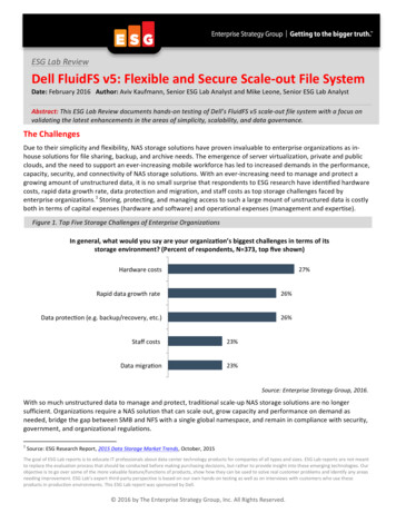
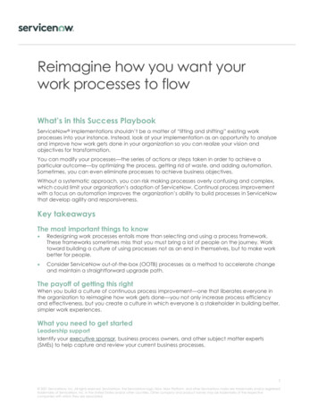
Proceedings of the Multidisciplinary Senior Design ConferencePage 2control valve to regulate the flow rate, which in turn will control the process temperature. The cart was only oneaspect of the project.The second aspect of the project was the design of a control system that would be used to analyze the signalsfrom the temperature sensors on the cart and convert that information into an action to change flow rate andeffectively control the temperature of the desired stream. This system uses four total temperature sensors. Thesesensors are used as inputs and feedback in a PID (Proportional Integral Derivative) control loop through a Labviewinterface. The control output sends a signal through a transducer to a valve that controls the flow rate of the processfluid through the heat exchanger.Heat exchangers are units used in many manufacturing processes to control the temperature of process lines.These units function by facilitating heat exchange across an interface that prevents the mixing of process fluids andcooling/heating fluids. The most common type of heat exchanger is a shell and tube (Figure 1). A shell and tube heatexchanger cools or heats the process fluid by circulating the exchange fluid around a central tube containing theprocess fluid.Figure 1:The cart design was based on the requirements of our customer, the chemical engineering department at theRochester Institute of Technology. These requirements were the baseline for component selection and for the natureof the laboratory objectives.Customer Requirements Design modeled after and consistent with existing flow cartsDesign to be modular and adaptableDesign to be portable, easily moved, easily connected and disconnected to lab utilitiesRobust and durable designMinimal maintenance and cleaningInterface with Labview Utilization can take place in allotted time for labUtilization safe and ergonomicOperated by 3 studentsUtilization requires fundamental understanding of Process Control Can be operated manually or through Labview interfaceData can be collected manuallyAutomated data collection through LabviewMeans to regulate flow of process fluidMeans to regulate flow of heating fluidControl temperature via regulating temperature or flowProject P13632
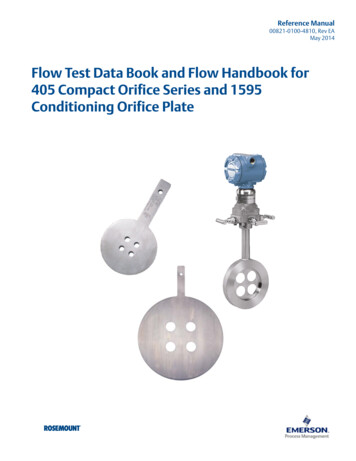
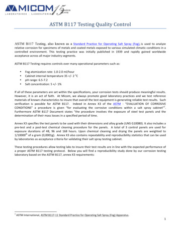
Proceedings of the Multi-Disciplinary Senior Design ConferencePage 3DESIGN PROCESSThrough collaboration with Dr. Christiaan Richter from the chemical engineering department, Steven Possanzafrom Kodak, and Dr. Michael Sanchez (the adjunct professor for the process controls class), the group consideredmultiple design options for the flow geometry and control technology. Figure 2 shows the results of this analysiswith the design decisions.Figure 2:The final design uses portable temperature baths to provide process fluid at set temperature points. The processcontrol component will be accomplished with a control valve placed on the inlet of the cooling flow to affect theoutlet temperature of the process fluid. A flow meter was added to the cold flow inlet to measure the flow rate of thecontrolled stream. In order to decrease the risk of student injury, the heat exchanger was used to cool the processfluid. This prevents the higher temperature flow of the heat exchange from being on the exterior of the design.Figure 3 shows mock ups of the overall cart design.Figure 3:The electrical design of the cart includes one RTD and one thermocouple at the input of the heat exchanger andone RTD and one thermocouple at the output of the heat exchanger. This was done in order to compare theeffectiveness and response times of various sensors on the heat exchange system (all of the sensor data is sampledby an MSP430G2553 chip, due to its low cost and analog-to-digital converter capabilities). The microcontrollersends this serial data to Labview through a UART (universal asynchronous receiver/transmitter) interface whichCopyright 2013 Rochester Institute of Technology
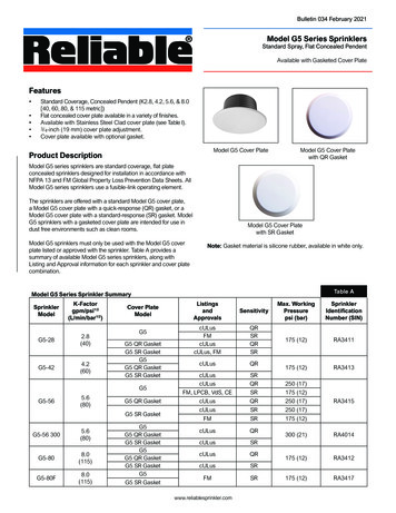
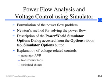
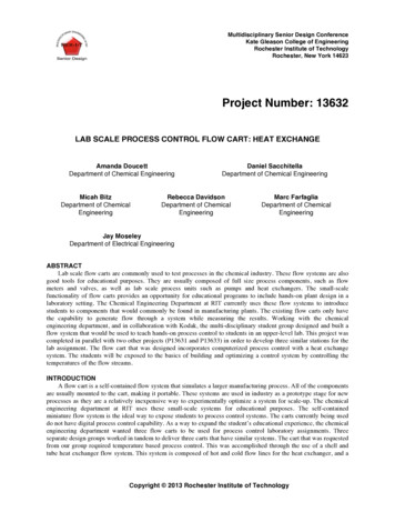
Proceedings of the Multidisciplinary Senior Design ConferencePage 4allows Labview and the microcontroller to communicate with one another. Using Labview’s available VirtualInstrument Software Architecture, serial data in ASCII format can be written to and from Labview. The softwaredeveloped in Labview records data from all 4 sensors, but only uses the two RTD sensors to create a PID controlloop. The PID variables and set point are modifiable by the user and the resulting output is written to anothermicrocontroller, which, using a serial peripheral interface (SPI), communicates with an MPC4812 digital to analogconverter (DAC). This produces an output between 0v and 5v. This is effectively the control signal for the valve.The signal is the input for a current source, with a 24v rail that will convert the 0v to 5v signal to a 4mA to 20mAinput signal for the transducer, which will provide a 3 to 15 psi control for the valve. An overview of the electricalsystem is shown below.Figure MSP430toMCP4808ICChipThermocoupleControlValveThe cart was constructed using a Rubbermaid wheeled cart with a capacity of up to 250 pounds. The structurewas fabricated with aluminum struts, and all of the components were mounted onto the structure. Figure 5 showsimages of the constructed cart.Figure 5:Project P13632
Proceedings of the Multi-Disciplinary Senior Design ConferencePage 5Once the cart was fully constructed the group performed testing to ensure that it functioned properly within thedesign parameters, and that it would meet the requirements of the customer for use in a future lab. Figure 6 showsthe test plan followed to ensure the final cart was performing to the desired specifications.Figure 6:Test IDT1T2T3T4Test NameRelevantSpecificationLeak TestMinimalCleaningAccuracy ofRotameterTemperatureSensorAccuracyOptimize N/ATemperatureControlN/AN/ARelevantCustomer NeedDescriptionCriticalValuePass/FailRobust DesignEnsure allconnections are tightand no liquid leaksfrom the systemPass/ValuePassRobust designThe measurementthe flow meteroutputs should beconfirms byexperimentallymeasuring a volumeof fluid collectedover a set timeperiod20%Pass, 8%discrepancyRobust DesignThe temperaturevalue thetemperature sensorsreturn will beconfirmed bycomparing thereadout to knownvaluesPass/FailPassTeachingTest heat exchangeover a range of inlettemperatures for thehot and cold streamsto optimize heatexchange settingsChange inhot stream10 15 in 30minutesStudent UseFull testing of alllabview interfaces toensurecommunication withthe computerPass/ FailPassStudent UseFull testing of labassignments toconfirm the timerequirments andresultsPass/FailCopyright 2013 Rochester Institute of Technology
Proceedings of the Multidisciplinary Senior Design ConferencePage 6RESULTS AND DISCUSSIONThe final product consists of a wheeled cart containing a heat exchanger, air regulator, valve, flow meter, fourtemperature sensors, and various tubes and fittings. Two water baths can be placed on an adjacent cart or on thecountertop to hold the process water, but they can be moved for increased portability. Process air and power areobtained from connections to lab utilities. The cart is integrated with a lab procedure that allows students to gain ahands-on understanding of process control, and has an equipment manual with all relevant data to fix any unforeseenmalfunctions.Due to a mechanical error, the cart was not functional for integrated testing at the time of this report. Themechanical and electrical portions were each tested separately and proved to be effective. No leaks were detectedupon start-up and throughout the various other tests performed. The temperature sensors, both the RTD’s andthermocouples, were proven to work correctly and register temperatures in the correct range. Precision of thesensors is more important than degree accuracy for this application as the change is what is analyzed. Effectivetemperature change was achieved, with a maximum heat exchange possible from the system proven to be fifteendegrees in approximately thirty minutes with a completely open valve. This proved that the cart is capable ofteaching heat control in the time provided. The Labview interface was also constructed and shown to workeffectively. The integration of the electrical system with the mechanical aspect of the cart was functional beforesoldering occurred, showing that the design communicated correctly with the cart components.When the circuits were transferred from the breadboard to the circuit boards all preliminary testing indicatedthat the transfer of components was successful. After installation, however, problems arose and it was determinedthat one of the chips was no longer operational. More testing was attempted and yet another component failed. Asfailure occurred between construction of the circuit boards and integration testing, it was determined that theinstallation into the electrical box must be at fault. Further investigation determined that the use of washers tostabilize the boards in the box caused the circuits to short, as the metal washers contacted and interfered in thecopper circuitry. This short caused multiple components in the circuit to malfunction and resulted in the failure ofthe circuit boards, preventing integrated testing.The functionality of the system was determined by the given specifications and guidelines from the customer.These requirements were compiled in the test plan, and systematically assessed. As shown, the cart was fullyfunctional before the circuits were transferred from the breadboard, and most of the specifications given were met.The rest of the requirements are not able to be tested until the cart is operational with the integrated electricalequipment. A path forward to achieve this condition is outlined below. The developed lab procedure in conjunctionwith the flow cart clearly taught process control in an interesting and innovative manner. The cart performedsatisfactorily in both mechanical and electrical aspects, with an equipment manual provided to ensure optimumperformance in the future. The portable design requested was achieved with the integration of all components on awheeled cart with standard fittings for all lab utilities. Manual operation is also possible in the event that Labview isunable to function correctly., while the standard operation involves the use of process control loops in Labview.CONCLUSIONS AND RECOMMENDATIONSThe overall success of the system is evident in the way in which the specifications were met, and this factoutweighs the failures encountered. There were areas of failure, however, and room for future improvement. Themain electrical failure was tied to mechanical sources and was a simple oversight instead of a lack of knowledge oreffort. While a Honey
fluid through the heat exchanger. Heat exchangers are units used in many manufacturing processes to control the temperature of process lines. These units function by facilitating heat exchange across an interface that prevents the mixing of process fluids and cooling/heating fluids. The most common type of heat exchanger is a shell and tube (Figure 1). A shell and tube heat exchanger cools or .