Transcription
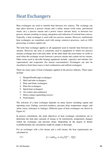
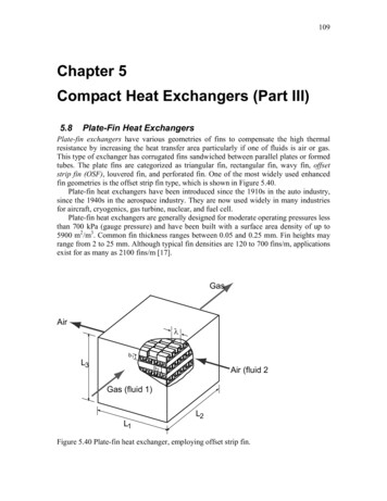
109Chapter 5Compact Heat Exchangers (Part III)5.8Plate-Fin Heat ExchangersPlate-fin exchangers have various geometries of fins to compensate the high thermalresistance by increasing the heat transfer area particularly if one of fluids is air or gas.This type of exchanger has corrugated fins sandwiched between parallel plates or formedtubes. The plate fins are categorized as triangular fin, rectangular fin, wavy fin, offsetstrip fin (OSF), louvered fin, and perforated fin. One of the most widely used enhancedfin geometries is the offset strip fin type, which is shown in Figure 5.40.Plate-fin heat exchangers have been introduced since the 1910s in the auto industry,since the 1940s in the aerospace industry. They are now used widely in many industriesfor aircraft, cryogenics, gas turbine, nuclear, and fuel cell.Plate-fin heat exchangers are generally designed for moderate operating pressures lessthan 700 kPa (gauge pressure) and have been built with a surface area density of up to5900 m2/m3. Common fin thickness ranges between 0.05 and 0.25 mm. Fin heights mayrange from 2 to 25 mm. Although typical fin densities are 120 to 700 fins/m, applicationsexist for as many as 2100 fins/m [17].GasAirλb1L3b2Air (fluid 2)Gas (fluid 1)L2L1Figure 5.40 Plate-fin heat exchanger, employing offset strip fin.
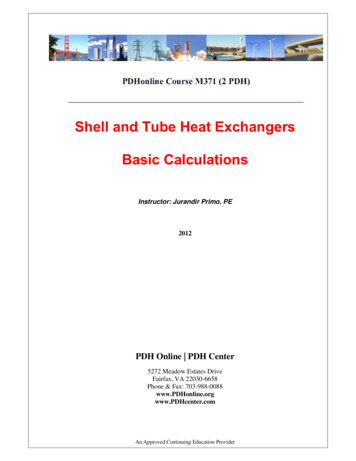
1100.5 (pf - δ)δwδPlateabb1el(b1 - δ)(b2 for fluid 2)FinFinδwjkfiδδPlatec dpfg hFigure 5.41 Schematic of offset strip fin (OSF) geometry5.8.1 Geometric CharacteristicsA schematic of a single-pass crossflow plate-fin heat exchanger, employing offset stripfins, is shown in Figure 5.40. The idealized fin geometry is shown in Figure 5.41.Defining the total heat transfer area for each fluid is important in the analysis. The totalarea consists of the primary area and the fin area. The primary area consists of the platearea except the fin base area, multi-passage side walls, and multi-passage front and backwalls. It is practical to assume that the numbers of passages for the hot fluid side and thecold fluid side are Np and Np 1 to minimize the heat loss to the ambient. The top andbottom passages in Figure 5.40 are designated to be cold fluid. The number of passages(don’t confuse with the number of passes) can be obtained from an expression for L3 asL3 N p b1{length of fluid 1 (N p 1)b2 2(N p 1)δ w14243 14243length of fluid 2(5.243)thickness of total platesSolving for Np gives the number of passages for hot fluidNp L3 b2 2δ wb1 b2 2δ w(5.244)By definition, the number of passages counts the number based on one flow passagebetween two plates, not all the individual channels between the plates. The total numberof fins for fluid 1 (hot) is calculated bynf1 L1Nppf1(5.245)For fluid 2 (cold),nf 2 L2(N p 1)pf 2(5.245a)
111where pf1 is the fin pitch that is usually obtained by making inverse of the fin density. Thetotal number of fins nf1 is based on the shaded area (a-c-d-e-f-g-h-j-a) in Figure 5.41counting as the unit fin. Since total primary area total plate areas – fin base areas passage side wall areas passage front and back wall areas, the primary area for fluid 1 isexpressed byAp1 2 L1 L2 N p 2δL2 n f 1 2b1 L2 N p 2(b2 2δ w )L1 (N p 1)14243 14243 14243 144424443total plate areafin base areapassage sidewall area(5.246)passage front and back wall areaThe number of offset strip fins noff1 per the number of fins is obtained bynoff 2 noff 1 L1(5.247)λ2L2(5.247a)λ1where λ1,2 is the offset strip fin length for fluid 1 and 2. The total fin area Af1 consists ofthe fin area and offset-strip edge areas.A f 1 2(b1 δ )L2 n f 1 2(b1 δ )δnoff 1n f 1 ( p f 1 δ )δ (noff 1 1)n f 1 1442443 1442443 144424443fin surface areas(d -e and g -f)offset -strip edge areas2(b-c -d -e)internal offset -strip edge area2(i- j-k -l-i)2 p f 1δn f 114243(5.248)1st & last offset -stripedge area , 2(a -b -i - j-a)Note that the cross-shaded area (a-b-l-k-a) was not included in the offset-strip edge areabecause the area is closely blocked by the next strip fin as shown in Figure 5.41 so thatno heat transfer at the area is expected. The total heat transfer area At1 is the sum of theprimary area and the fin area asAt1 Ap1 A f 1(5.249)The free-flow (cross sectional) area Ac1 is obtained byAc1 (b1 δ )( p f 1 δ )n f 1(5.250)It is assumed in Equation (5.250) that there exists a small gap between the offset strip fins,whereby the next strip fin shown in the unit fin in Figure 5.41 is not considered as anobstructing structure to the free flow. The frontal area Afr1 for fluid 1 where fluid 1 isentering is defined byA fr1 L1 L3(5.251)
112The hydraulic diameter for fluid 1 is generally defined byDh1 4 Ac1 L2At1(5.252)For the fin efficiency ηf of the offset strip fin, it is assumed that the heat flow from bothplates is uniform and the adiabatic plane occurs at the middle of the plate spacing b1.Hence, the fin profile length Lf1 is defined byLf1 b1 δ2(5.253)The m value is obtained using Equation (5.96) asm1 2hkfδ δ 1 λ1 (5.254)The single fin efficiency ηf is obtained using Equation (5.95) byηf tanh (m1 L f 1 )(5.255)m1 L f 1The overall surface (fin) efficiency ηo is then obtained using Equations (5.99), (5.248)and (5.249) asη o1 1 Af 1At1(1 η )f(5.256)5.8.2 Correlations for Offset Strip Fin (OSF) GeometryThis geometry has one of the highest heat transfer performances relative to the frictionfactors. Extensive analytical, numerical and experimental investigations have beenconducted over the last 50 years. The most comprehensive correlations for j and f factorsfor the laminar, transition, and turbulent regions are provided by Manglik and Bergles[27] in 1995 as follows.
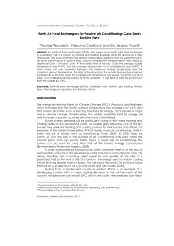
113j 0.6522 Re 0.5403 pf δ b δ 0.1541 pf δ 1 5.269 10 5 Re1.34 b δ pf δf 9.6243 Re 0.7422 b δ δ λ 0.504 0.1856 p δ 1 7.669 10 8 Re 4.429 f b δ 0.1499 δ λ δ λ 0.92 δ p δ f0.4560.3053 δ λ 0.0678 δ p δ f δ p δ f3.767 1.055 (5.257) 0.2659 δ p δ f 0.236 (5.258)where the hydraulic diameter was defined by them asDh MB 4( p f δ )(b δ )λ2(( p f δ )λ (b δ )λ (b δ )δ ) ( p f δ )δ(5.258)This is an approximation of Equation (5.252). However, Equation (5.258) is in excellentagreement with Equation (5.252), which indicates the general definition of hydraulicdiameter, Equation (5.252), can be used in place of Equation (5.258). The correlations ofManglik and Bergles [27] were compared with the experiments (surface 1/8-19.86)reported by Kays and London [8] in Figure 5.42. The comparison for both j and f showsgood agreement. Note that the comparison covers from laminar through turbulent regions.
1141f0.1j0.01 31 1010031 101 104ReFigure 5.42 Colburn factor j and friction factor f for offset-strip-fin (OSF) type plate-finheat exchangers. The correlation of Manglik and Bergles [27] were compared with theexperiments (1/8-19.86 surface) of Kays and London [8].
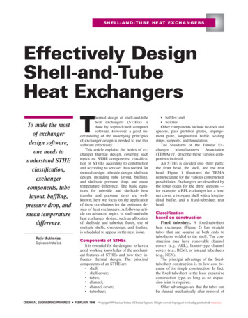
115Example 5.8.1 Plate-Fin Heat ExchangerA gas-to-air single-pass crossflow heat exchanger is designed for heat recovery from theexhaust gas to preheat incoming air in a solid oxide fuel cell (SOFC) co-generationsystem. Offset strip fins of the same geometry are employed on the gas and air sides; thegeometrical properties and surface characteristics are provided in Figures E5.8.1 andE5.8.2. Both fins and plates (parting sheets) are made from Inconel 625 with k 18 W/mK.The anode gas flows in the heat exchanger at 3.494 m3/s and 900 C. The cathode air onthe other fluid side flows at 1.358 m3/s and 200 C. The inlet pressure of the gas is at 160kPa absolute whereas that of air is at 200 kPa absolute. Both the gas and air pressuredrops are limited to 10 kPa. It is desirable to have an equal length for L1 and L2. Design agas-to-air single-pass crossflow heat exchanger operating at ε 0.824. Determine the coredimensions of this exchanger. Then, determine the heat transfer rate, outlet fluidtemperatures and pressure drops on each fluid. Use the properties of air for the gas. Usealsothe following geometric information given.DescriptionFin thickness δPlate thickness δwFin density NfSpacing between plates b1 and b2Offset strip length λ1 and λ2value0.102 mm0.5 mm782 m-12.49 mm3.175 mmGasAirλb1L3b2Air (fluid 2)Gas (fluid 1)L2L1Figure E5.8.1 Plate-fin heat exchanger, employing offset strip fin.
1160.5 (pf - δ)δwδPlateabb1jkeif(b1 - δ)(b2 for fluid 2)lFinFinδwδδc dPlateg hpfFigure E5.8.2 Schematic of offset strip fin (OSF) geometryMathCAD format solution:Design concept is to develop a MathCAD model as a function of the dimensions of thesizing and then solve the sizing with the design requirements.Properties:We will use the arithmetic average temperatures as the appropriate mean temperature oneach side by assuming the outlet temperatures at this time.Tgas : 900 C 400 C2 923.15K 200 C 600 CTair : 2Gas (subscript 1)Air (subscript 2)ρ1ρ2defined latercp1 : 1126JWk1 : 0.063m K(E5.8.2)Jkg KWk2 : 0.0524m K 6 N sµ 1 : 40.1 102 6 N sµ 2 : 33.6 10mPr1 : 0.731(E5.8.1)defined latercp2 : 1073kg K 673.15K 2mPr2 : 0.694The thermal conductivities of the fins and walls are given asWkf : 18m KWkw : 18m K(E5.8.3)
117Given information:T1i : 900 Cgas inlet temperatureT2i : 200 Cair inlet temperatureP1i : 160kPagas inlet pressureP2i : 200kPaair inlet pressure(E5.8.4)(E5.8.5)(E5.8.6)(E5.8.7)3mQ1 : 3.494svolume flow rate at gas side(E5.8.8)3mQ2 : 1.358svolume flow rate at air side(E5.8.9)Air and gas densities (inlet):The gas constants for air is known to beJR2 : 287.04kg K(E5.8.10)We calculate the air and gas inlet densities using the ideal gas law with an assumptionthat the gas constants for air and gas are equal.assumingR1 : R2(E5.8.11)P1iρ1i : R1 T1ikgρ1i 0.4753mP2iρ2i : R2 T2ikgρ2i 1.4733m(E5.8.12)(E5.8.13)Hence, the mass flow rate for each fluid is calculated asmdot1 : ρ1i Q1mdot2 : ρ2i Q2mdot1 1.66mdot2 2kgs(E5.8.14)kgs(E5.8.15)
118Design requirements:In this design problem, the effectiveness is major concern for heat recovery. Thedesigners want to derive the relationship between the effectiveness and the sizing. Thefrontal widths for both fluids are required to be the same (L1 L2).εeffectiveness0.824 P 1 10kPapressure drop at gas side P 2 10kPapressure drop at air 19)Geometric information:δ : 0.102mmfin thicknessδw : 0.5mmplate thickness(E5.8.21) 1Nf : 782mp f1 : (E5.8.20)fin density(E5.8.22)1fin pitchNf(E5.8.22a)p f2 : p f1p f1 1.2788mm b 1 : 2.49mmplate distance(E5.8.23)(E5.8.24)b 2 : 2.49mm(E5.8.25)λ 1 : 3.175mmoffset strip length(E5.8.26)λ 2 : 3.175mm(E5.8.27)Assume the sizing of the heat exchangerInitially, assume the sizing to have the instant values and update later the dimensionswhen the final sizing is determined.L1 : 0.303mL2 : 0.303mL3 : 0.948m(E5.8.28)It is assumed that the number of passages for the gas side and the air side are Np and Np 1,respectively, to minimize the heat loss to the ambient. Using Equation (5.243), L3 iscalculated by
119()()Np b 1 Np 1 b 2 2 Np 1 δwL3(E5.8.29)Thus, the total number of passages Np for the gas side is obtained using Equation (5.244)L3 Np L3 : b1 ( )b 2 2 δw( )Np L3 157.945b 2 2 δw(E5.8.30)Note that the total number of passages is a function of L3. The total number of fins foreach fluid is obtainedL1n f1 L1 , L3 : N Lp f1 p 3()( )()4(E5.8.31)L2n f2 L2 , L3 : N L 1p f2 p 3()n f1 L1 , L3 3.7424 10( ( ))()4n f2 L2 , L3 3.7661 10(E5.8.32)The total primary area Ap for each fluid is calculated using Equation (5.246).()( )()( )() ( ( ))A p1 L1 , L2 , L3 : 2 L1 L2 Np L3 2 δ L2 n f1 L1 , L3 2 b 1 L2 Np L3 2 b 2 2 δw L1 Np L3 1(E5.8.33)()( ( ))()( ( ))()( )A p2 L1 , L2 , L3 : 2 L1 L2 Np L3 1 2 δ L1 n f2 L2 , L3 2 b 2 L1 Np L3 1 2 b 1 2 δw L2 Np L3(E5.8.34)()(2A p1 L1 , L2 , L3 27.263m)2A p2 L1 , L2 , L3 27.431m(E5.8.35)The number of offset strip fins for each fluid (per the number of fins) is obtainedL2n off1 L2 : λ1L1n off2 L1 : λ2( )( )(E5.8.36)The total fin area Af for each fluid is obtained using Equation (5.248) as()()() () (( ) ) ()()A f1 L1 , L2 , L3 : 2 b 1 δ L2 n f1 L1 , L3 p f1 δ δ n off1 L2 1 n f1 L1 , L3 2 p f1 δ n f1 L1 , L3(E5.8.37)
120()()() () (( ) ) ()()A f2 L1 , L2 , L3 : 2 b 2 δ L1 n f2 L2 , L3 p f2 δ δ n off2 L1 1 n f2 L2 , L3 2 p f2 δ n f2 L2 , L3(E5.8.38)()(2A f1 L1 , L2 , L3 54.592m)2A f2 L1 , L2 , L3 54.937m(E5.8.39)The total surface area At for each fluid is the sum of the fin area Af and the primary areaAp .()()()()()()()A t1 L1 , L2 , L3 : A f1 L1 , L2 , L3 A p1 L1 , L2 , L3(E5.8.40)A t2 L1 , L2 , L3 : A f2 L1 , L2 , L3 A p2 L1 , L2 , L3(E5.8.41)(2A t1 L1 , L2 , L3 81.855m)2A t2 L1 , L2 , L3 82.369m(E5.8.42)The free-flow area Ac for each side is obtained using Equation (5.250) as() ()() ()A c1 L1 , L3 0.1052m() ()() ()A c2 L2 , L3 0.1058mA c1 L1 , L3 : b 1 δ p f1 δ n f1 L1 , L3A c2 L2 , L3 : b 2 δ p f2 δ n f2 L2 , L3()2()2(E5.8.43)(E5.8.44)The frontal area for each fluid is defined using Equation (5.251) by()A fr1 L1 , L3 0.287m()A fr2 L2 , L3 0.287mA fr1 L1 , L3 : L1 L3A fr2 L2 , L3 : L2 L3()2()2(E5.8.45)(E5.8.46)The hydraulic diameter is defined using Equation (5.252) by()4 A c1 L1 , L3 L2Dh1 L1 , L2 , L3 : A t1 L1 , L2 , L3()(())4 A c2 L2 , L3 L1Dh2 L1 , L2 , L3 : A t2 L1 , L2 , L3()()()Dh1 L1 , L2 , L3 1.557 mm(E5.8.47)()Dh2 L1 , L2 , L3 1.557 mm(E5.8.48)The hydraulic diameter of Equation (5.258) defined by Manglik and Bergles [27] iscalculated in Equation (E5.8.49) to compare with the general definition of Equation(E5.8.47). We find that they are in good agreement. Therefore, we use Equations(E5.8.47) and (E5.8.48) in the rest of the calculations.
121()4 p f1 δ b 1 λ 1Dh M
Compact Heat Exchangers (Part III) 5.8 Plate-Fin Heat Exchangers Plate-fin exchangers have various geometries of fins to compensate the high thermal resistance by increasing the heat transfer area particularly if one of fluids is air or gas. This type of exchanger has corrugated fins sandwiched between parallel plates or formed tubes.