Transcription
C H A P T E R 17HEAT EXCHANGERSR. K. Shah* and D. R SekulibUniversity of KentuckyINTRODUCTIONA heat exchanger is a device that is used for transfer of thermal energy (enthalpy) betweentwo or more fluids, between a solid surface and a fluid, or between solid particulates and afluid, at differing temperatures and in thermal contact, usually without external heat andwork interactions. The fluids may be single compounds or mixtures. Typical applicationsinvolve heating or cooling of a fluid stream of concern, evaporation or condensation of a single or multicomponent fluid stream, and heat recovery or heat rejection from a system. Inother applications, the objective may be to sterilize, pasteurize, fractionate, distill, concentrate, crystallize, or control process fluid. In some heat exchangers, the fluids exchanging heatare in direct contact. In other heat exchangers, heat transfer between fluids takes placethrough a separating wall or into and out of a wall in a transient manner. In most heatexchangers, the fluids are separated by a heat transfer surface, and ideally they do not mix.Such exchangers are referred to as the direct transfer type, or simply recuperators. In contrast,exchangers in which there is an intermittent heat exchange between the hot and cold fluidsmvia thermal energy storage and rejection through the exchanger surface or matrix--arereferred to as the indirect transfer type or storage type, or simply regenerators. Such exchangers usually have leakage and fluid carryover from one stream to the other.A heat exchanger consists of heat exchanging elements such as a core or a matrix containing the heat transfer surface, and fluid distribution elements such as headers, manifolds, tanks,inlet and outlet nozzles or pipes, or seals. Usually there are no moving parts in a heatexchanger; however, there are exceptions such as a rotary regenerator (in which the matrix ismechanically driven to rotate at some design speed), a scraped surface heat exchanger, agitated vessels, and stirred tank reactors.The heat transfer surface is a surface of the exchanger core that is in direct contact with fluids and through which heat is transferred by conduction. The portion of the surface that alsoseparates the fluids is referred to as the primary or direct surface. To increase heat transferarea, appendages known as fins may be intimately connected to the primary surface to provide extended, secondary, or indirect surface. Thus, the addition of fins reduces the thermalresistance on that side and thereby increases the net heat transfer from/to the surface for thesame temperature difference. The heat transfer coefficient can also be higher for fins.A gas-to-fluid heat exchanger is referred to as a compact heat exchanger if it incorporatesa heat transfer surface having a surface area density above about 700 m2/m3 (213 ft2/ft 3) on at*Current address: Delphi Harrison ThermalSystems,Lockport,New York.17.1
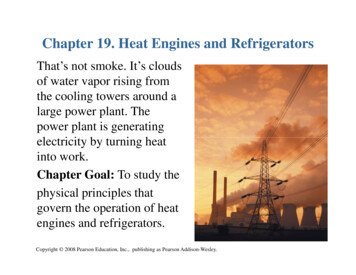
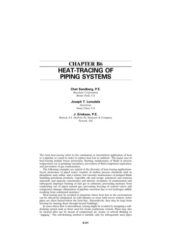
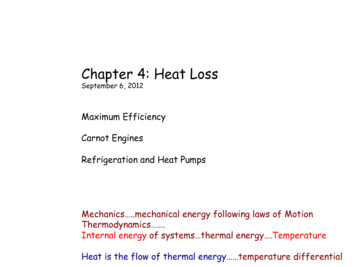
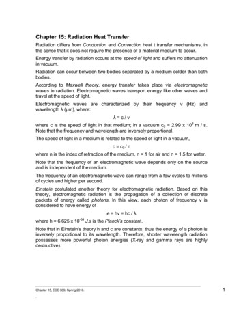
17.2CHAPTERSEVENTEENleast one of the fluid sides, which usually has gas flow. It is referred to as a laminar flow heatexchanger if the surface area density is above about 3000 m2/m3 (914 ft2/ft3), and as a microheat exchanger if the surface area density is above about 10,000 m2/m3 (3050 ft2/ft3). A liquid/two-phase fluid heat exchanger is referred to as a compact heat exchanger if the surface areadensity on any one fluid side is above about 400 m2/m3 (122 ft2/ft3). A typical process industryshell-and-tube exchanger has a surface area density of less than 100 m2/m3 on one fluid sidewith plain tubes and 2-3 times that with the high-fin-density, low-finned tubing. Plate-fin,tube-fin, and rotary regenerators are examples of compact heat exchangers for gas flows onone or both fluid sides, and gasketed and welded plate heat exchangers are examples of compact heat exchangers for liquid flows.CLASSIFICATION OF HEAT EXCHANGERSHeat exchangers may be classified according to transfer process, construction, flow arrangement, surface compactness, number of fluids and heat transfer mechanisms as shown in Fig.17.1 modified from Shah [1] or according to process functions as shown in Fig. 17.2 [2]. A briefdescription of some of these exchangers classified according to construction is provided nextalong with their selection criteria. For further general description, see Refs. 1-4.Shell-and-Tube ExchangersThe tubular exchangers are widely used in industry for the following reasons. They are customdesigned for virtually any capacity and operating conditions, such as from high vacuums toultra-high pressures (over 100 MPa or 15,000 psig), from cryogenics to high temperatures(about ll00 C, 2000 F), and any temperature and pressure differences between the fluids,limited only by the materials of construction. They can be designed for special operating conditions: vibration, heavy fouling, highly viscous fluids, erosion, corrosion, toxicity, radioactivity, multicomponent mixtures, and so on. They are the most versatile exchangers made from avariety of metal and nonmetal materials (graphite, glass, and Teflon) and in sizes from small(0.1 m 2, 1 ft 2) to super-giant (over 100,000 m 2, 10 6 ft2). They are extensively used as processheat exchangers in the petroleum-refining and chemical industries; as steam generators, condensers, boiler feed water heaters, and oil coolers in power plants; as condensers and evaporators in some air-conditioning and refrigeration applications; in waste heat recoveryapplications with heat recovery from liquids and condensing fluids; and in environmental control.Shell-and-tube exchangers are basically noncompact exchangers. Heat transfer surfacearea per unit volume ranges from about 50 to 100 mZ/m3 (15 to 30 ft2/ft3). Thus, they require aconsiderable amount of space, support structure, and capital and installation costs. As aresult, overall they may be quite expensive compared to compact heat exchangers. The latterexchangers have replaced shell-and-tube exchangers in those applications today where theoperating conditions permit such use. For the equivalent cost of the exchanger, compact heatexchangers will result in high effectiveness and be more efficient in energy (heat) transfer.Shell-and-tube heat exchangers are classified and constructed in accordance with thewidely used Tubular Exchanger Manufacturers Association (TEMA) standards [5], DIN andother standards in Europe and elsewhere, and ASME Boiler and Pressure Vessel Codes.TEMA has developed a notation system to designate the main types of shell-and-tubeexchangers. In this system, each exchanger is designated by a three-letter combination, the firstletter indicating the front-end head type, the second the shell type, and the third the rear-endhead type. These are identified in Fig. 17.3. Some of the common shell-and-tube exchangersare BEM, BEU, BES, AES, AEP, CFU, AKT, and AJW. Other special types of commerciallyavailable shell-and-tube exchangers have front-end and rear-end heads different from those inFig. 17.3; these exchangers may not be identifiable by the TEMA letter designation.
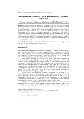
HEAT EXCHANGERS17.3C l a s s i f i c a t i o n a c c o r d i n g to t r a n s f e r p r o c e s sIIIIndirect contact typeDirect contact typeI!Direct transfer typeI,!Storage typeFluidized bedIImmiscible aseC l a s s i f i c a t i o n a c c o r d i n g to n u m b e r of fluids,ITwo-fluidThree-fluidN-fl d(N 3)C l a s s i f i c a t i o n a c c o r d i n g to s u r f a c e c o m p a c t n e s sI, ,,,,,,iIGas-to-fluidLiquid to liquid or phase changeI!Compact(13 700m2/m3)IiiNon-compactCompactiNon-compact(13 700m2/m3) (13 400m2/m3)(13 400 m2/m3)Classification according to c o n s t r u c t i o nI!ITubularPlate-typeIIIIIIIiIIIRotary Fixed-matrixTube-fin' -Pipecoils Ord'inaNHeat-pipeseparating wallwallPlate-finiShell-and-tube Spiral tubeaiICrossflow Parallelflowto tubesto tubesIRegeneralJveIP ESpiral Platecoil Printed' !ci rcu itIIGasketed Welded BrazedDouble-pipeIExtended surfaceRotatinghoodsC l a s s i f i c a t i o n a c c o r d i n g to flow a r r a n g e m e n t w CrossflowSplit-flowIIDivided-flowIIIExtended surfaceShell-and-tube,ICrosscounterflow,,Cross- CompoundparallelflowflowIParallel counterflowM shell passesN tube passesIPlateI,Fluid 1 m passesFluid 2 n passesSplit-flow Divided-flowClassification a c c o r d i n g to heat t r a n s f e r m e c h a n i s m sISingle-phase convectionon both sidesIISingle-phase convectionon one side, two-phaseconvection on other sideFIGURE 17.1 Classification of heat exchangers.IITwo-phase convectionon both sidesCombined convectionand radiative heat transfer
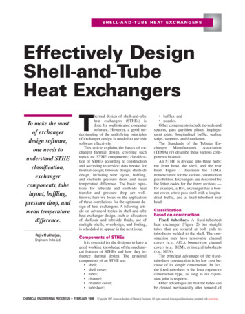
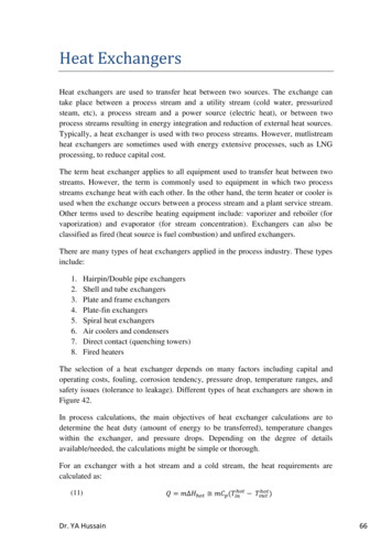
17.4CHAPTERSEVENTEENClassificationaccordingto process densersHeatersChillersCoolers(a)Condemt4 rsI,Direct contact,,ISpray and trayIPoolIPacked columnIPower industryIISurface condenserIIndirect contact Process industryIFeedwater heaterIRate-typeExtended JIXITotalcondensationIIIRefluxKnockbackPlateIspir g exchangers (unfired)Boilers (fired)ISteam generators for,WatercooledreactorsIGascooledreactors/Vertical calandriaIWaste heat boilers,,ILiquid metalcooledreactorsIBayonet t u b zontalcrossfow(c)FIGURE 17.2 (a) Classification according to process function. (b) Classificationof condensers. (c) Classification of liquid-to-vapor phase-change exchangers.The three most common types of shell-and-tube exchangers are fixed tubesheet design,U-tube design, and the floating head type. In all types, the front-end head is stationary, whilethe rear-end head could be either stationary or floating depending upon the thermal stressesin the shell, tube, or tubesheet due to temperature differences as a result of heat transfer.The exchangers are built in accordance with three mechanical standards that specifydesign, fabrication, and materials of unfired shell-and-tube heat exchangers. Class R is forgenerally severe requirements of petroleum and related processing applications. Class C is forgenerally moderate requirements for commercial and general process applications. Class B isfor chemical process service. The exchangers are built to comply with the applicable ASME(American Society of Mechanical Engineers) Boiler and Pressure Vessel Code Section VIII,or other pertinent codes and/or standards. The TEMA standards supplement and define theASME code for heat exchanger applications. In addition, the state and local codes applicableto the plant location must also be met. In this chapter, we use the TEMA standards, but thereare other standards such as DIN 28 008.
HEAT EXCHANGERSFront EndStationary Head TypesRear EndHead TypesShell TypesI !T17.5%-,---fffl ! ]Fixed TubesheetLike "A' Stationary HeadOne Pass Shelli TChanneland Removable CoverI ]IFixed TubesheetLike "B' Stationary HeadTwo Pass Shellwith Longitudinal BaffleiFixed TubesheetLike 'N" Stationary HeadSplit FlowBonnet (Integral Cover)i Ti. !i .L1' - [ Outside Packed Floating HeadDouble Split FlowChannel Integral with TubeSheet and Removable Cover.TFloating Headwith Backing DeviceDivided Flow.l., ' , . L LL.,C'. . -.-- !,: .i I "TPull Through Floating Head!Channel Integral with TubeSheet and Removable Cover.LKettle Type ReboilerU-Tube BundleL F ,! LSpecial High Pressure ClosureF I G U R E 17.3Cross FlowExtemally SealedFloating TubesheetStandard front-end head, shell-type, and rear-end head types, from T E M A [5].The T E M A standards specify the manufacturing tolerances for various mechanical classes,the range of tube sizes and pitches, baffling and support plates, pressure classification,tubesheet thickness formulas, and so on, and must be consulted for all these details.Criteria for Mechanical SelectionShells. Shells are generally made from standard pipes for shell diameters less than 610mm (2 ft) and by rolling and welding plates to the desired diameters for larger sizes. The shelldiameters range from less than 50 mm (2 in) to 6.10 m (20 ft) for special applications. The Eshell (see Fig. 17.3) is a single-pass shell that is economical and usually has the most efficientthermal arrangement (i.e., it has the highest mean temperature difference correction factor
17.6CHAPTER SEVENTEENF). However, if the F factor is low enough to require two E shells in series for multipass tubeside exchangers, the F shell (a two-pass shell; a counterflow unit) can be used as an equivalentbut more economical unit. However, the F shell baffle is subject to fluid and thermal leakageacross the longitudinal baffle, so it must be carefully designed and constructed. It also provides more problems in removing or replacing the tube bundle. The F shell is used for singlephase applications. If the pressure drop in an F shell is limiting, a split-flow G or H shell canbe used with some sacrifice in the F factor. The G shell is used in many applications, with theshellside thermosiphon and forced convective boiling as one of the common applications. Ifshellside pressure drop becomes limiting, the divided-flow J shell is used; however, there issome loss in the thermal efficiency (a lower F factor). The J shell is commonly used in vacuumcondensing applications. The X shell is used for large shell flows or for the lowest shellside Apfor a given flow rate. In the X shells, full-size support plates are used to prevent tube vibration. For high flow rates (inlet velocity), alternately H or J shells with two inlet nozzles areused. The G and H shells are seldom used for shellside single-phase applications, since thereis no advantage over E or X shells. They are used for thermosiphon reboilers, condensers, andother phase-change applications. The K shell is exclusively used for vaporization of liquid onthe
A heat exchanger consists of heat exchanging elements such as a core or a matrix contain- ing the heat transfer surface, and fluid distribution elements such as headers, manifolds, tanks, inlet and outlet nozzles or pipes, or seals. Usually there are no moving parts in a heat exchanger; however, there are exceptions such as a rotary regenerator (in which the matrix is mechanically driven to .File Size: 2MBPage Count: 169