Transcription
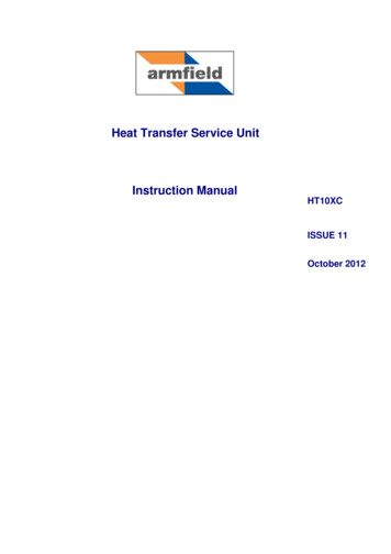
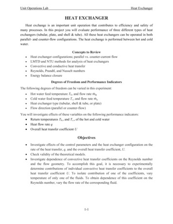
CHAPTER 6HEAT TRANSFER APPLICATIONSThe principles of heat transfer are widely used in food processing in many items ofequipment. It seems appropriate to discuss these under the various applications that arecommonly encountered in nearly every food factory.HEAT EXCHANGERSIn a heat exchanger, heat energy is transferred from one body or fluid stream to another. Inthe design of heat exchange equipment, heat transfer equations are applied to calculate thistransfer of energy so as to carry it out efficiently and under controlled conditions. Theequipment goes under many names, such as boilers, pasteurizers, jacketed pans, freezers, airheaters, cookers, ovens and so on. The range is too great to list completely. Heat exchangersare found widely scattered throughout the food process industry.Continuous-flow Heat ExchangersIt is very often convenient to use heat exchangers in which one or both of the materials thatare exchanging heat are fluids, flowing continuously through the equipment and acquiring orgiving up heat in passing. One of the fluids is usually passed through pipes or tubes, and theother fluid stream is passed round or across these. At any point in the equipment, the localtemperature differences and the heat transfer coefficients control the rate of heat exchange.The fluids can flow in the same direction through the equipment, this is called parallel flow;they can flow in opposite directions, called counter flow; they can flow at right angles to eachother, called cross flow. Various combinations of these directions of flow can occur indifferent parts of the exchanger. Most actual heat exchangers of this type have a mixed flowpattern, but it is often possible to treat them from the point of view of the predominant flowpattern. Examples of these heat exchangers are illustrated in Figure 6.1.In parallel flow, at the entry to the heat exchanger, there is the maximum temperaturedifference between the coldest and the hottest stream, but at the exit the two streams can onlyapproach each other's temperature. In a counter flow exchanger, leaving streams canapproach the temperatures of the entering stream of the other component and so counter flowexchangers are often preferred.
Figure 6.1 Heat exchangersApplying the basic overall heat transfer equation for the heat transfer in the heat exchanger:q UA Tuncertainty at once arises as to the value to be chosen for T, even knowing the temperaturesin the entering and leaving streams.Consider a heat exchanger in which one fluid is effectively at a constant temperature, Tb asillustrated in Fig. 6.1(d), where time t is on the x-axis and temperature T on the y-axis.Constant temperature in one component can result either from a very high flow rate of thiscomponent compared with the other component, or from the component being a vapour suchas steam or ammonia condensing at a high rate, or from a boiling liquid. The heat transfercoefficients are assumed to be independent of temperature.The rate of mass flow of the fluid that is changing temperature is G kgs-1, its specific heat iscp J kg-1oC -1. Over a small length of path of area dA, the mean temperature of the fluid is Tand the temperature drop is dT over time dt. The constant temperature fluid has a temperatureTb. The overall heat transfer coefficient is U J m-2s-1 oC-1Therefore the heat balance over the short length is:cpGdT U(T - Tb)dATherefore(U / cpG) dA dT /(T –T b)
If this is integrated over the length of the tube in which the area changes from A 0 to A A, and T changes from T1 to T2, we have: ln[(T1 – T b)/(T2 - Tb)] ln( T1/ T2) T1 (T1 – T b) and T2 (T2 – T b)(U/cpG) Ain whichThereforecpGwhere ln loge UA/ ln ( T1/ T2)From the overall equation, the total heat transferred per unit time is given byq UA Tmwhere Tm is the mean temperature difference.But the total heat transferred per unit is also:q cpG (T1 –T 2)soq UA Tm cpG (T1 –T 2)[UA/ ln ( T1/ T2)] x (T1 –T 2)but (T1 –T 2) can be written (T1 – T b) - (T2 - Tb)so(T1 –T 2 ) ( T1 - T2)thereforeUA Tm UA( T1 - T2) / ln ( T1/ T2)(6.1) Tm(6.2)so that ( T1 - T2) / ln( T1/ T2)where Tm is called the log mean temperature difference.In other words, the rate of heat transfer can be calculated using the heat transfer coefficient,the total area, and the log mean temperature difference. This same result can be shown tohold for parallel flow and counter flow heat exchangers in which both fluids change theirtemperatures.The analysis of cross-flow heat exchangers is not so simple, but for these also the use of thelog mean temperature difference gives a good approximation to the actual conditions if onestream does not change very much in temperature.EXAMPLE 6.1. Cooling of milk in a pipe heat exchangerMilk is flowing into a pipe cooler and passes through a tube of 2.5cm internal diameter at arate of 0.4 kgs-1. Its initial temperature is 49oC and it is wished to cool it to 18oC using astirred bath of constant 10oC water round the pipe. What length of pipe would be required?Assume an overall coefficient of heat transfer from the bath to the milk of 900Jm -2s-1 oC-1,and that the specific heat of milk is 3890 Jkg-1oC-1.
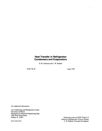
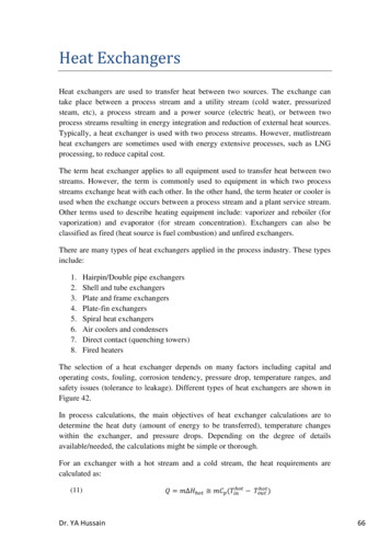
NowAlsoq cpG (T1 –T 2) 3890 x 0.4 x (49 - 18) 48,240Js-1q UA Tm Tm [(49 - 10) - (18 –10)] / ln[(49 -10)1(18 - 10)] 19.6oC.Therefore48,240 900 x A x l9.6A 2.73m2butA DLwhere L is the length of pipe of diameter DNowD 0.025m.L 2.73/( x 0.025) 34.8mThis can be extended to the situation where there are two fluids flowing, one the cooled fluidand the other the heated fluid. Working from the mass flow rates (kgs-1) and the specific heatsof the two fluids, the terminal temperatures can normally be calculated and these can then beused to determine Tm and so, from the heat transfer coefficients, the necessary heat-transfersurface.EXAMPLE 6.2. Water chilling in a counter flow heat exchangerIn a counter flow heat exchanger, water is being chilled by sodium chloride brine. If the rateof flow of the brine is 1.8 kgs-1 and that of the water is 1.05 kgs-1, estimate the temperature towhich the water is cooled if the brine enters at –8oC and leaves at 10C, and if the water entersthe exchanger at 32oC.If the area of the heat-transfer surface of this exchanger is 55 m2, what is the overall heattransfer coefficient? Take the specific heats to be 3.38 and 4.18kJkg-1oC-1for the brine and thewater respectively.With heat exchangers a small sketch is often helpful. In this counter flow exchanger, Figure6.2, the brine flows along the top (temperatures T1 and T2), and water along the bottom(temperatures T1’and T2’).
Figure 6.2. Diagrammatic heat exchangerThree temperatures are known and the fourth T 2 can be found from the heat balance:Brine: entering T1 -8oC, leaving T2 10oC Water: entering T2 32oC, leaving T1 Heat gain in brine heat loss in watercpG (T1 –T 2) cpG (T1 –T 2 )3.38 x 1.8 [10 - (-8)] 4.18 x 1.05 x (32 – T2‘)(32 – T1‘) 25oThereforeT1‘ 7 C.And so for counter flow(T1 –T1 ) T1 (T2 –T2 ) T2 T1 [-8 - 7] 15oC and T2 [10 - 32] 22oC.Therefore Tm (22 - 15)/ln(22/15) 7/0.382 18.3oC.For the heat exchanger, from the heat balance, heat loss from brine heat gain to waterq heat passed across heat transfer surface UA TmTherefore3.38 x 1.8 x 18 U x 55 x 18.3U 0.11kJm-2s-1oC-1Overall heat transfer coefficient 110 Jm-2s-1oC-1Parallel flow can be worked out similarly making appropriate adjustments.In some cases, heat exchanger problems cannot be solved so easily; for example, if the heattransfer coefficients have to be calculated from the basic equations of heat transfer whichdepend on flow rates and temperatures of the fluids, and the temperatures themselves dependon the heat transfer coefficients. The easiest way to proceed then is to make sensibleestimates and to go through the calculations. If the final results are coherent, then theestimates were reasonable. If not, then make better estimates, on the basis of the results, andgo through a new set of calculations; and if necessary repeat again until consistent results areobtained. For those with multiple heat exchangers to design, computer programmes areavailable.
Jacketed PansIn a jacketed pan, the liquid to be heated is contained in a vessel, which may also be providedwith an agitator to keep the liquid on the move across the heat-transfer surface, as shown inFig. 6.3(a).Figure 6.3 Heat exchange equipmentThe source of heat is commonly steam condensing in the vessel jacket. Practicalconsiderations are:1. There is the minimum of air with the steam in the jacket.2. The steam is not superheated, as part of the surface must then be used as a de-superheaterover which low gas heat transfer coefficients apply rather than high condensingcoefficients.3. Steam trapping to remove condensate and air is adequate.
The action of the agitator and its ability to keep the fluid moved across the heat transfersurface are important. Some overall heat transfer coefficients are shown in Table 6.1. Savefor boiling water, which agitates itself, mechanical agitation is assumed. Where there is noagitation, coefficients may be halved.TABLE 6.1SOME OVERALL HEAT TRANSFER COEFFICIENTS IN JACKETED PANSCondensing t-ironCast-ironStainless steelCopperThin liquidThick liquidPasteWater, boilingHeat transfer coefficientsJm-2s-1oC-118009003001800EXAMPLE 6.3. Steam required to heat pea soup in jacketed panEstimate the steam requirement as you start to heat 50kg of pea soup in a jacketed pan, if theinitial temperature of the soup is 18oC and the steam used is at 100kPa gauge. The pan has aheating surface of 1 m2 and overall heat transfer coefficient is assumed to be 300 Jm-2s-1oC-1.From steam tables (Appendix 8), saturation temperature of steam at l00kPa gauge 120 oCand latent heat 2202kJkg-1.q UA T 300 x 1 x (120 - 18) 3.06 x 10⁴ Js-1Therefore amount of steam q/ (3.06 x 10⁴)/(2.202 x 106 ) 1.4 x 10 -2kgs -1 1.4 x 10-2 x 3.6 x 103 50kgh-1.This result applies only to the beginning of heating; as the temperature rises less steam willbe consumed as T decreases.The overall heating process can be considered by using the analysis that led up to eqn. (5.6).A stirred vessel to which heat enters from a heating surface with a surface heat transfercoefficient which controls the heat flow, follows the same heating or cooling path as does asolid body of high internal heat conductivity with a defined surface heating area and surfaceheat transfer coefficient.EXAMPLE 6.4. Time to heat pea soup in a jacketed panIn the heating of the pan in Example 6.3, estimate the time needed to bring the stirred peasoup up to a temperature of 90oC, assuming the specific heat is 3.95 kJkg-1oC -1.From eqn. (5.6)(T2 - Ta)/(T1 – Ta) exp(-hsAt/c V )Ta 120oC (temperature of heating medium)T1 18oC (initial soup temperature)T2 90oC (soup temperature at end of time t)
ThereforehsA V 300 Jm-2s-1oC -1 1m2, c 3.95 kJkg-1oC -1. 50kgt -3.95 x 103 x 50 x ln 90 -120300 x 118 -120 (-658) x (-1.22) s 803s 13.4min.Heating Coils Immersed in LiquidsIn some food processes, quick heating is required in the pan, for example, in the boiling ofjam. In this case, a helical coil may be fitted inside the pan and steam admitted to the coil asshown in Fig. 6.3(b). This can give greater heat transfer rates than jacketed pans, becausethere can be a greater heat transfer surface and also the heat transfer coefficients are higherfor coils than for the pan walls. Examples of the overall heat transfer coefficient U are quotedas: 300-1400 for sugar and molasses solutions heated with steam using a copper coil, 1800 for milk in a coil heated with water outside, 3600 for a boiling aqueous solution heated with steam in the coil.with the units in these coefficients being Jm-2 s-1oC -1.Scraped Surface Heat ExchangersOne type of heat exchanger, that finds considerable use in the food processing industryparticularly for products of higher viscosity, consists of a jacketed cylinder with an internalcylinder concentric to the first and fitted with scraper blades, as illustrated in Fig. 6.3(c). Theblades rotate, causing the fluid to flow through the annular space between the cylinders withthe outer heat transfer surface constantly scraped. Coefficients of heat transfer vary withspeeds of rotation but they are of the order of 900-4000 Jm-2s-1oC -1. These machines are usedin the freezing of ice cream and in the cooling of fats during margarine manufacture.Plate Heat ExchangersA popular heat exchanger for fluids of low viscosity, such as milk, is the plate heatexchanger, where heating and cooling fluids flow through alternate tortuous passagesbetween vertical plates as illustrated in Fig. 6.3(d). The plates are clamped together, separatedby spacing gaskets, and the heating and cooling fluids are arranged so that they flow betweenalternate plates. Suitable gaskets and channels control the flow and allow parallel or countercurrent flow in any desired number of passes. A substantial advantage of this type of heatexchanger is that it offers a large transfer surface that is readily accessible for cleaning. Thebanks of plates are arranged so that they may be taken apart easily. Overall heat transfercoefficients are of the order of 2400-6000 Jm-2 s-1oC -1.
THERMAL PROCESSINGThermal processing implies the controlled use of heat to increase, or reduce depending oncircumstances, the rates of reactions in foods.A common example is the retorting of canned foods to effect sterilization. The object ofsterilization is to destroy all microorganisms, that is, bacteria, yeasts and moulds, in the foodmaterial to prevent decomposition of the food, which makes it unattractive or inedible. Also,sterilization prevents any pathogenic (disease-producing) organisms from surviving andbeing eaten with the food. Pathogenic toxins may be produced during storage of the food ifcertain organisms are still viable. Microorganisms are destroyed by heat, but the amount ofheating required for the killing of different organisms varies. Also, many bacteria can exist intwo forms, the vegetative or growing form and the spore or dormant form. The spores aremuch harder to destroy by heat treatment than are the vegetative forms. Studies of themicroorganisms that occur in foods, have led to the selection of certain types of bacteria asindicator organisms. These are the most difficult to kill, in their spore forms, of the types ofbacteria which are likely to be troublesome in foods.A frequently used indicator organism is Clostridium botulinum. This particular organism is avery important food-poisoning organism as it produces a deadly toxin and also its spores areamongst the most heat resistant. Processes for the heat treatment of foodstuffs are thereforeexamined with respect to the effect they would have on the spores of C. botulinum. If the heatprocess would not destroy this organism then it is not adequate. As C. botulinum is a verydangerous organism, a selected strain of a non-pathogenic organism of similar heat resistanceis often used for testing purposes.Thermal Death TimeIt has been found that microorganisms, including C. botulinum, are destroyed by heat at ratesthat depend on the temperature, higher temperatures killing spores more quickly. At anygiven temperature, the spores are killed at different times, some spores being apparently moreresistant to heat than other spores. If a graph is drawn, the number of surviving spores againsttime of holding at any chosen temperature, it is found experimentally that the number ofsurviving spores fall asymptotically to zero. Methods of handling process kinetics are welldeveloped and if the standard methods are applied to such results, it is found that thermaldeath of microorganisms follows, for practical purposes, what is called a first-order process ata constant temperature (see for example Earle and Earle, 2003). This implies that thefractional destruction in any fixed time interval is constant. It is thus not possible, in theory atleast, to take the time when all of the organisms are actually destroyed. Instead it ispracticable, and very useful, to consider the time needed for a particular fraction of theorganisms to be killed.The rates of destruction can in this way be related to:(1) The numbers of viable organisms in the initial container or batch of containers.(2) The number of viable organisms that can safely be allowed to survive.
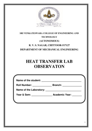
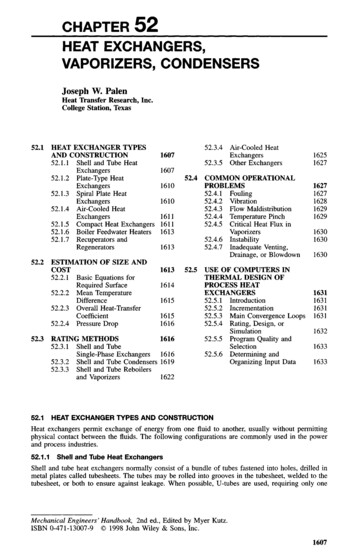
Of course the surviving number must be small indeed, very much less than one, to ensureadequate safety. However, this concept, which includes the admissibility of survival numbersof much less than one per container, has been found to be very useful. From suchconsiderations, the ratio of the initial to the final number of surviving organisms becomes thecriterion that determines adequate treatment. A combination of historical reasons andextensive practical experience has led to this number being set, for C. botulinum, at 1012:1.For other organisms, and under other circumstances, it may well be different.The results of experiments to determine the times needed to reduce actual spore counts from1012 to 1 (the lower, open, circles) or to 0 (the upper, closed, circles) are shown in Fig. 6.4. 93C100C 110C120C130CTemperature oCFigure 6.4. Thermal death time curve for Clostridium botulinumBased on research results from the American Can Company
In this graph, these times are plotted against the different temperatures and it shows that whenthe logarithms of these times are plotted against temperatures, the resulting graph is a straightline. The mean times on this graph are called thermal death times for the correspondingtemperatures. Note that these thermal death times do not represent complete sterilization, buta mathematical concept which can be considered as effective sterilization, which is in fact asurvival ratio of 1:1012, and which has been found adequate for safetyAny canning process must be considered then from the standpoint of effective sterilization.This is done by combining the thermal death time data with the temperature/timerelationships at the point in the can that heats slowest. Generally, this point is on the axis ofthe can and somewhere close to the geometric centre. Using either the unsteady-state heatingcurves or experimental measurements with a thermocouple at the slowest heating point in acan, the temperature/time graph for the can under the chosen conditions can be plotted. Thiscurve has then to be evaluated in terms of its effectiveness in destroying C. botulinum or anyother critical organism, such as thermophilic spore formers, which are important in industry.In this way the engineering data, which provides the temperatures within the container as theprocess is carried out, are combined with kinetic data to evaluate the effect of processing onthe product.Considering Fig. 6.4, the standard reference temperature is generally selected as 121.1oC(250 oF), and the relative time (in minutes) required to sterilize, effectively, any selectedorganism at 121oC is spoken of as the F value of that organism. In our example, reading fromFig. 6.4, the F value is about 2.8 min. For any process that is different from a steady holdingat 121oC, our standard process, the actual attained F values can be worked out by stepwiseintegration. If the total F value so found is below 2.8 min, then sterilization is not sufficient;if above 2.8 min, the heat treatment is more drastic than it needs to be.Equivalent Killing Power at Other TemperaturesThe other factor that must be determined, so that the equivalent killing powers attemperatures different from 121oC can be evaluated, is the dependence of thermal death timeon temperature. Experimentally, it has been found that if the logarithm of t, the thermal deathtime, is plotted against the temperature, a straight-line relationship is obtained. This is shownin Fig. 6.4 and more explicitly in Fig. 6.5 where the x-axis is oC and y-axis is time.
Figure 6.5 Thermal death time/temperature relationshipsWe can then write from the graphlog t - log F m(121 –T) log t/Fwhere t is the thermal death time at temperature T, F is the thermal death time at temperature1210C (t121 F)and m is the slope of the graph.Also, if we define the z value as the number of degrees below 121oC at which t increases by afactor of 10, that is by one cycle on a logarithmic graph,t l0F when T (121 - z)so that,log 10F – logF log (10F/F) 11 m[121 - (121 - z)]and soz 1/mThereforelog (t/F)ort (121 - T)/ z F x 10(121-T )/z(6.3) t121 x 10(121-T )/zNow, the fraction of the process towards reaching thermal death, dS, accomplished in time dtis given by (1/t1)dt, where t1 is the thermal death time at temperature T1, assuming that thedestruction is additive.That isdS (1/t1)dt
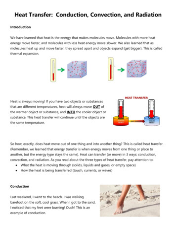
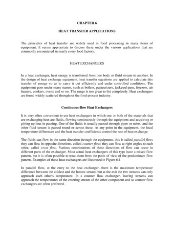
or (1/F)10-(l21-T)/ z dtWhen the thermal death time has been reached, that is when effective sterilization has beenachieved, dS 1that is (1/F) 10-(l21-T)/ zdt 1or 10-(l21-T)/ z dt F(6.4)This implies that the sterilization process is complete, that the necessary fraction of thebacteria/spores have been destroyed, when the integral is equal to F. In this way, the factors Fand z can be combined with the time-temperature curve and integrated to evaluate asterilizing process.The integral can be evaluated graphically or by stepwise numerical integration. In stepwisenumerical integration, the contribution towards F of a period of t min at a temperature T isgiven by t x 10-(121 -t)/z Breaking up the temperature-time curve into t1 min at T1, t2 mm at T2,etc., the total F is given byF(i.e.t121 ) t1 x 10-(l21-T1 )/ z t2 x 10-(121-T2)/z .This value of F is then compared with the standard value of F for the organism, for example2.8 min for C. botulinum in our example, to decide whether the sterilizing procedure isadequate.EXAMPLE 6.5. Time/Temperature in a can during sterilisationIn a retort, the temperatures in the slowest heating region of a can of food were measured andwere found to be as shown in Fig. 6.6. Is the retorting adequate, if F for the process is 2.8 mmand z is 10oC?
Figure 6.6 Time/Temperature curve for can processingApproximate stepped temperature increments are drawn on the curve giving the equivalentholding times and temperatures as shown in Table 6.2. The corresponding F values arecalculated for each temperature step.TABLE 6.2TIMES/TEMPERATURES IN CANNING STERILISATIONTemperature TimeT (oC)t 08706(121 - T)4131262116131211142131415110-(121-T)/l 07.9 x 10-57.9 x 10-42.5 x 10-37.9 x 10-32.5 x 10-25.0 x 10-26.3 x 10-27.9 x 10-24.0 x 10-27.9 x 10-37.9 x 10-47.9 x 10-57.9 x 10-6t x10-(121 .0160.00160.00060.00005Total 2.64
The above results show that the F value for the process 2.64 so that the retorting time is notquite adequate. This could be corrected by a further 2 min at 110oC (and proceeding as above,this would add 2 x 10-(121 - 110)/10 0.16, to 2.64, making 2.8).From the example, it may be seen that the very sharp decrease of thermal death times withhigher temperatures means that holding times at the lower temperatures contribute little to thesterilization. Very long times at temperatures below 90oC would be needed to make anyappreciable difference to F, and in fact it can often be the holding time at the highesttemperature which virtually determines the F value of the whole process. Calculations can beshortened by neglecting those temperatures that make no significant contribution, although,in each case, both the number of steps taken and also their relative contributions should bechecked to ensure accuracy in the overall integration.It is possible to choose values of F and of z to suit specific requirements and organisms thatmay be suspected of giving trouble. The choice and specification of these is a whole subjectin itself and will not be further discussed. From an engineering viewpoint a specification isset, as indicated above, with an F value and a z value, and then the process conditions aredesigned to accomplish this.The discussion on sterilization is designed to show, in an elementary way, how heat-transfercalculations can be applied and not as a detailed treatment of the topic. This can be found inappropriate books such as Stumbo (1973), Earle and Earle (2003).PasteurizationPasteurization is a heat treatment applied to foods, which is less drastic than sterilization, butwhich is sufficient to inactivate particular disease-producing organisms of importance in aspecific foodstuff. Pasteurization inactivates most viable vegetative forms of microorganismsbut not heat-resistant spores.Originally, pasteurization was evolved to inactivate bovine tuberculosis in milk. Numbers ofviable organisms are reduced by ratios of the order of 1015:1. As well as the application toinactivate bacteria, pasteurization may be considered in relation to enzymes present in thefood, which can be inactivated by heat. The same general relationships as were discussedunder sterilization apply to pasteurization. A combination of temperature and time must beused that is sufficient to inactivate the particular species of bacteria or enzyme underconsideration. Fortunately, most of the pathogenic organisms, which can be transmitted fromfood to the person who eats it, are not very resistant to heat.The most common application of pasteurization is to liquid milk. In the case of milk, thepathogenic organism that is of classical importance is Mycobacterium tuberculosis, and thetime/temperature curve for the inactivation of this bacillus is shown in Fig. 6.7.
Figure 6.7 Pasteurization curves for milkThis curve can be applied to determine the necessary holding time and temperature in thesame way as with the sterilization thermal death curves. However, the times involved arevery much shorter, and controlled rapid heating in continuous heat exchangers simplifies thecalculations so that only the holding period is really important. For example, 30min at 62.8 oCin the older pasteurizing plants and 15sec at 71.7oC in the so-called high temperature/shorttime (H.T.S.T.) process are sufficient. An even faster process using a temperature of 126.7 oCfor 4 sec is claimed to be sufficient. The most generally used equipment is the plate heatexchanger and rates of heat transfer to accomplish this pasteurization can be calculated by themethods explained previously.An enzyme present in milk, phosphatase, is destroyed under somewhat the same temperature/time conditions as the M. tuberculosis and, since chemical tests for the enzyme can becarried out simply, its presence is used as an indicator of inadequate heat treatment. In thiscase, the presence or absence of phosphatase is of no significance so far as the storageproperties or suitability for human consumption are concerned.Enzymes are of importance in deterioration processes of fruit juices, fruits and vegetables. Iftemperature/time relationships, such as those that are shown in Fig. 6.7 for phosphatase, canbe determined for these enzymes, heat processes to destroy them can be designed. Most oftenthis is done by steam heating, indirectly for fruit juices and directly for vegetables when theprocess is known as blanching.
The processes for sterilization and pasteurization illustrate very well the application of heattransfer as a unit operation in food processing. The temperatures and times required aredetermined and then the heat transfer equipment is designed using the equations developedfor heat-transfer operations.EXAMPLE 6.6. Pasteurisation of milkA pasteurization heating process for milk was found, taking measurements and times, toconsist essentially of three heating stages being 2min at 64oC, 3min at 65oC and 2min at66oC. Does this process meet the standard pasteurization requirements for the milk, asindicated in Fig. 6.7, and if not what adjustment needs to be made to the period of holding at66oC?From Fig. 6.7, pasteurization times tT can be read off the UK pasteurisation standard, andfrom and these and the given times, rates and fractional extents of pasteurization can becalculated.sososoAt 64oC, t642 min is 215.7oAt 65 C, t653 min is 39.2At 66oC, t662 min is 25.4Total pasteurization extent 15.7 min 0.13 9.2 min 0.33 5.4 min 0.37 (0.13 0.33 0.37) 0.83.Pasteurization remaining to be accomplished (1 - 0.83) 0.17.At 66oC this would be obtained from (0.17 x 5.4) min holding 0.92 min.oSo an additional 0.92 min (or approximately 1 min) at 66 C would be needed to meet thespecification.REFRIGERATION, CHILLING AND FREEZINGRates of decay and of deterioration in foodstuffs depend on temperature. At suitable lowtemperatures, changes in the food can be reduced to economically acceptable levels. Thegrowth and metabolism of microorganisms is slowed down and if the temperature is lowenough, growth of all microorganisms virtually ceases. Enzyme activity and chemicalreaction rates (of fat oxidation, for example) are also very much reduced at thesetemperatures. To reach temperatures low enough for deterioration virtually to cease, most ofthe water in the food must be frozen. The effect of chilling is only to slow down deteriorationchanges.In studying chilling and freezing, it is necessary to look first at the methods for obtaining lowtemperatures, i.e. refrigeration systems, and then at the coupling of these to the food productsin chilling and freezing.
Refrigeration CycleThe basis of mechanical refrigeration is the fact that at different pressures the saturation (orthe condensing) temperatures of vapours are different as clearly shown on the appropriatevapour-pressure/temperature curve. As the pressure increases condensing temperatures alsoincrease. This fact is applied in a cyclic process, which is illustrated in Fig. 6.8.Figure 6.8 Mechanical refrigeration circuitTh
Figure 6.1 Heat exchangers Applying the basic overall heat transfer equation for the heat transfer in the heat exchanger: q UA T uncertainty at once arises as to the value to be chosen for T, even know