Transcription
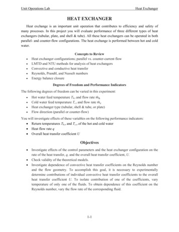
Unit Operations LabHeat ExchangerHEAT EXCHANGERHeat exchange is an important unit operation that contributes to efficiency and safety ofmany processes. In this project you will evaluate performance of three different types of heatexchangers (tubular, plate, and shell & tube). All these heat exchangers can be operated in bothparallel- and counter-flow configurations. The heat exchange is performed between hot and coldwater. Concepts to ReviewHeat exchanger configurations; parallel vs. counter-current flowLMTD and NTU methods for analysis of heat exchangersConvective and conductive heat transferReynolds, Prandtl, and Nusselt numbersEnergy balance closureDegrees of Freedom and Performance IndicatorsThe following degrees of freedom can be varied in this experiment: Hot water feed temperature Th,i and flow rateCold water feed temperature Tc,i and flow rateHeat exchanger type (tubular, shell & tube, or plate)Flow direction (parallel or counter-flow)You will investigate effects of these variables on the following performance indicators: Return temperatures Th,o and Tc,o of the hot and cold water Heat flow rate q Overall heat transfer coefficient UObjectives Investigate effects of the control parameters and the heat exchanger configuration on therate of the heat transfer, q, and the overall heat transfer coefficient, U.Check validity of the theoretical models.Investigate dependence of convective heat transfer coefficients on the Reynolds numberand the flow geometry. To accomplish this goal, it is necessary to experimentallydetermine contributions of individual convective heat transfer coefficients to the overallheat transfer coefficient U. To isolate contribution of one of the coefficients, varytemperature of only one of the fluids. To obtain dependence of this coefficient on theReynolds number, vary the flow rate of the corresponding fluid.1-1
Unit Operations LabHeat ExchangerTheoryNotes1. The theory presented here is based on Ref. 1. Please refer to this book for more details.2. Subscripts h and c refer to the hot and cold fluids, respectively, and subscripts i and o refer tothe inlet and outlet of the heat exchanger, respectively. E.g., Th,i denotes temperature of thehot fluid at the inlet and Tc,o denotes temperature of the cold fluid at the outlet.Overall Heat Transfer Coefficient UConsider energy balance in a differential segment of a single-pass heat exchanger shownschematically in Fig. 1-1. The rate of heat transfer in this segment is(1) ,where U is the overall heat transfer coefficient, ΔT is the local temperature difference betweenthe hot and cold fluids, and dA is the contact area in the differential segment.The overall heat transfer coefficient is inversely proportional to the total resistance Rtot tothe heat flow. The latter is the sum of (1) resistance Rconv,h to convective heat transfer from thehot fluid to the partition between the fluids, (2) resistance Rp to thermal conduction through thepartition, and (3) resistance Rconv,c to convective heat transfer from the partition to the cold fluid.Therefore,11(2).,,Figure 1-1. Energy balance in a differential element of a single pass heat exchanger operated in the counter-flowregime. Red, blue, and gray colors represent the hot fluid, cold fluid, and the partition between the fluids,respectively. The dashed rectangle shows a differential segment corresponding to the energy balance Eq. (1). Threeresistances (Rconv,h, Rp, and Rconv,c) contributing to the total resistance to the heat transfer are indicated schematically.Convective heat transfer. Resistance to the convective heat transfer is inverselyproportional to the convective heat transfer coefficient, h 1/Rconv. The convective heat transfer1-2
Unit Operations LabHeat Exchangercoefficient depends on fluid properties, flow geometry, and the flow rate. It is convenient todescribe this dependence using several dimensionless numbers, namely the Reynold number(3),the Prandltl number,(4)and the Nusselt number.(5)Here, ρ, μ, k, and cp are the density, viscosity, thermal conductivity, and heat capacity of the fluid,v is the flow velocity, and L is characteristic length. The choice of L depends on the systemgeometry. For example, for a flow in a circular pipe, L is the pipe diameter.Relationship between Re, Pr, and Nu depends on the system geometry and whether theflow is laminar and turbulent. For example, for a turbulent flow inside a pipe with circular crosssection of diameter D,./(6)0.027As a part of your pre-lab homework, you should find all correlations relevant to the geometriesand the flow regimes considered in this experiment.Conductive heat transfer. The resistance Rp to heat transfer through the partitiondepends on the system geometry. In the current experiment, you will need to consider heatconduction in the radial direction of a cylindrical tube and heat conduction across a thin plate.Resistances in both of these cases can be obtained analytically be solving the heat diffusionequation. You should obtain Rp for all considered heat exchangers as a part of your pre-labhomework.Relationships between Overall Heat Transfer Coefficient and the Inletand Outlet Fluid TemperaturesIn the previous section we discussed heat transfer in a differential segment of the heatexchanger. Here, we analyze the heat transfer in the entire heat exchanger. Heat exchangers areusually analyzed using either the Logarithmic Mean Temperature Difference (LMTD) or theEffectiveness – Number of Transfer Units (ε-NTU) methods. The LMTD method is convenientfor determining the overall heat transfer coefficient based on the measured inlet and outlet fluidtemperatures. The ε-NTU method is more convenient for prediction of the outlet fluidtemperatures if the heat transfer coefficient and the inlet temperatures are known.The analysis presented below assumes that1. There is no energy loss to the environment2. Heat exchanger is at a steady-state1-3
Unit Operations LabHeat Exchanger3. There are no phase changes in the fluids4. Heat capacities of the fluids are independent of temperature5. Overall heat transfer coefficient is independent of the fluid temperature and positionwithin the heat exchanger.Since all heat exchangers considered in this experiment have a single pass for both the hot andcold fluids, the discussion below is limited to single-pass heat exchangers. Qualitativedependence of the fluid temperature on position inside a single-pass heat exchanger is shown inFig. 1-2.Logarithmic Mean Temperature Difference (LMTD) MethodThe total heat transfer rate is(7),where dq is given by Eq. (1) and points 1 and 2 are defined in Fig. 1-2. This integral cannot becomputed by a direct integration of Eq. (1), since ΔT typically varies with position in the heatexchanger, as shown in Fig. 1-2.Figure 1-2. Temperature profiles in (a) counter-flow and (b) parallel flow single pass heat exchangers. Note that in acounter-flow heat exchanger the outlet temperature of the cold fluid can exceed the outlet temperature of the hotfluid but this cannot happen in a parallel flow system.However, it is possible to obtain q by combining Eq. (1) with energy balances indifferential segments of the heat exchanger,(8)Here, dTk is the temperature change of fluid k (k c or h) in the interval under consideration, andCk is the heat capacity rate of fluid k,,or ,1-4(9)
Unit Operations LabwhereyieldsHeat Exchangerand ck are the mass flow rate and heat capacity of fluid k, respectively. This analysis (10),where A is the total contact area and ΔTlm is the logarithmic mean temperature difference(LMTD), – ln / (11)Here, ΔTk refers to temperature difference between the hot and cold fluids at point k (k 1 or 2),i.e. ,,and ,,,and ,,(12)for the counter-current flow and ,(13)for the parallel flow.Notes1. If heat capacity rates of the cold and hot fluids are the same and the heat exchanger isoperated in the counter-flow regime then ΔT is independent of position in the heat exchanger.In this case Eqs. (10), (11) are not applicable and the total heat transfer rate q should beobtained by direct integration of Eq. (1).2. This result holds for single pass heat exchangers only. However, LMTD method can beextended to more complex heat-exchanger designs (e.g., multi-pass and cross-flow systems)using a correction factor (see Ref. 1).Effectiveness-NTU MethodLMTD method is useful for determining the overall heat transfer coefficient U based onexperimental values of the inlet and outlet temperatures and the fluid flow rates. However, thismethod is not very convenient for prediction of outlet temperatures if the inlet temperatures andU are known. In this case, one has to solve a nonlinear system of two equations (Eq. (10) and theoverall energy balance) for two unknowns (Th,o and Tc,o). This solution requires application of aniterative approach.A more convenient method for predicting the outlet temperatures is the effectivenessNTU method. This method can be derived from the LMTD method without introducing anyadditional assumptions. Therefore, the effectiveness-NTU and LMTD methods are equivalent.An advantage of the effectiveness-NTU method is its ability to predict the outlet temperatureswithout resorting to a numerical iterative solution of a system of nonlinear equations.The heat-exchanger effectiveness ε is defined as1-5
Unit Operations LabHeat Exchanger(14),where q is the actual rate of heat transfer from the hot to cold fluid and qmax is the maximumpossible rate of heat transfer for given inlet temperatures of the fluids,(15),,Here, Cmin is the smaller of the two heat capacity rates Cc and Ch. If heat exchanger effectivenessis known, one can readily obtain q from equations (14) and (15). After that, the outlettemperatures can be obtained from the energy balance.The efficiency ε depends on the heat exchanger geometry, flow pattern (parallel flow,counter-flow, cross-flow, etc.) and the number of transfer units(16).Relationships between the effectiveness and NTU have been established for a large variety ofheat exchanger configurations. Most of these relationships involve the ratio Cr Cmin/Cmax of thesmaller and the larger of the heat capacity rates Cc and Ch. For example, for a single pass heatexchanger in the parallel flow regimeε1exp1(17)1and for a single pass heat exchanger in the counter-flow regime,εε111expexpif111.if1(18)(19)References1. F. P. Incropera, D. P. DeWitt, T. L. Bergman, and A. S. Lavine, “Fundamentals of Heat andMass Transfer”, 6th ed. (Wiley, 2007).1-6
Unit Operations Lab Heat Exchanger 1-4 3. There are no phase changes in the fluids 4. Heat capacities of the fluids are independent of temperature 5. Overall heat transfer coefficient is independent of the fluid temperature and position within the heat exchanger. Since all heat exchangers considered in this experiment have a single pass for both the hot and cold fluids, the discussion below is .