Transcription
ARF Design ConsiderationsBy: Andrew Chen, VP of TechnologyWith Contributions from Sean Querry, Electrical Engineer InternDecember 16, 2015Version 1.0RF hardware design is complex and oftentimes a challenge for embedded designers. Forinstance, parasitic effects that are not typically a concern in low- frequency applicationscan have a major impact on radio frequency performance as you move into higherfrequency ranges. Different wireless hardware designs also require special certificationrequirements and designing and testing wireless hardware takes special skills andequipment. These are only a few factors that must be considered.
RF Design ConsiderationsWhite PaperREVISION HISTORYVersionDateNotesApprover1.016 Dec 2015Initial ReleaseAndrew ChenEmbedded Wireless Solutions Support ch.com/wireless2LairdAmericas: 1-800-492-2320Europe: 44-1628-858-940Hong Kong: 852-2923-0610
RF Design ConsiderationsWhite PaperCONTENTSIntroduction . 4What is RF?. 4Model for a Resistor . 5Different Package . 5Model for an Inductor . 6Model for a Capacitor. 6PCB Design Considerations . 6Characteristic Impedance Matching . 6Transmission Line . 7Antenna Placement . 7Types of Antennas . 7Parasitic Effects during Design . 9DFX Considerations . 11Design for Passing Certification (FCC/CE/IC) . 11Design for Manufacturing and Test . 11Conclusion . 11Embedded Wireless Solutions Support ch.com/wireless3LairdAmericas: 1-800-492-2320Europe: 44-1628-858-940Hong Kong: 852-2923-0610
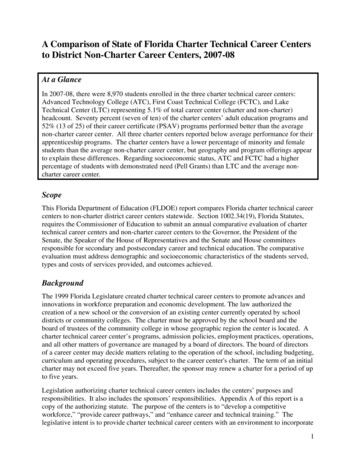
RF Design ConsiderationsWhite PaperINTRODUCTIONRF hardware design is complex and oftentimes a challenge for embedded designers. For instance, parasiticeffects that are not typically a concern in low frequency applications can have a major impact on radiofrequency performance as you move into higher frequency ranges. Different wireless hardware designs alsorequire special certification requirements and designing and testing wireless hardware takes a special set ofskills and equipment. These are only a few factors that must be considered. This white paper explores some ofthe key components of RF design and their implications on system performance. Topics include a review of RFand the characteristics engineers should be aware of, basic components and potential parasitic effects, PCBdesign characteristics including impedance matching, transmission line, and antenna selection and placement,and DFX considerations.WHAT IS RF?RF, short for radio frequency, commonly refers to wireless communications occupying the radio frequencyportion of the electromagnetic spectrum. RF has many applications as you can see in Figure 1, but of whatcharacteristics must users be aware? For wireless communications, frequencies can range from several hertz(Hz) to over 300 gigahertz (GHz). Devices such as AM/FM radios, remote controls, TV, cellphones, GPS, and somemedical devices operate in relatively low frequency ranges, typically less than one GHz. Compared tofrequencies in the five GHz or ten GHz range, these low frequencies offer a wider coverage area for a giventransmit power; they also have the advantage of being able to propagate through dense objects, not requiringline of sight. For example, cellphones are designed to operate within the 900 megahertz (MHz) to 1.8 GHz rangebecause they need to penetrate walls and other dense objects for indoor coverage. At 2.4 GHz, signals havedifficulty going through dense objects like concrete and metal, which attenuate the signal. These harshenvironments cause difficulty for 2.4 GHz signals, therefore roaming and antenna diversity are necessary toensure devices stay connected. Again, a drawback of higher frequencies is that signals require line of sight foroperation. However, higher frequencies offer the advantage of higher available channel bandwidth whichtranslates to higher data throughput.For example, Wi-Fi designs using the 802.11 a/b/g/n standards have a minimum 20 MHz channel bandwidth inthe 2.4/5 GHz range. With 802.11ac, the channel bandwidth ranges from 80 MHz to 160 MHz in the 5 GHz rangeonly. This allows for an increased data rate but if the frequency increases, the fractional bandwidth decreasesmaking system design more difficult. Also, higher frequency signals attenuate much more quickly in air. In short,high frequencies cannot drive a very high output power. To compensate for this however, you can easily designa higher gain antenna with little size penalty. Thus, with high frequency designs, you cannot deliver a highoutput power, but a higher gain antenna can be used to compensate for the weaker signal.Figure 1: Uses of the RF spectrumEmbedded Wireless Solutions Support ch.com/wireless4LairdAmericas: 1-800-492-2320Europe: 44-1628-858-940Hong Kong: 852-2923-0610
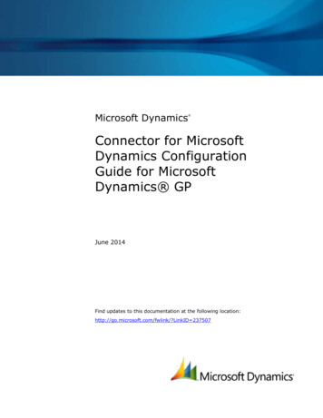
RF Design ConsiderationsWhite PaperBASIC COMPONENTSIn any electronics hardware design there are three basic passive components: resistor, inductor, and capacitor.In digital designs these components can generally be assumed as ideal and parasitic effects can be neglected.This is not the case with RF. In RF designs, frequency-dependent behavior must be taken into account, thereforethe component models become more complex. How do we manage this?Model for a ResistorThe model for a resistor is complicated as shown in Figure 2. Its behavior is frequency-dependent; at DC or lowfrequency, the inductive and capacitive effects can be ignored. However that is not the case for higherfrequencies. The higher the frequency, the greater the likelihood of parasitic effects impacting the signal. Whendesigning circuits for the 2.4 GHz and 5 GHz frequency bands used for 802.11 Wi-Fi, these effects must beconsidered.Figure 2: Typical high-frequency performance electrical model for resistorDifferent PackageWhen designing RF circuits, we must consider that a resistor’s high frequency parasitic effects can be dependenton package type and size. For example, larger packages such as the 0805 are not suitable when used at higherfrequencies due to these effects being particularly pronounced (Figure 3).Figure 3: High frequency electrical characteristicEmbedded Wireless Solutions Support ch.com/wireless5LairdAmericas: 1-800-492-2320Europe: 44-1628-858-940Hong Kong: 852-2923-0610
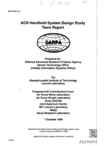
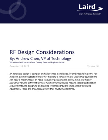
RF Design ConsiderationsWhite PaperModel for an InductorLike resistors, the behavior of inductors is frequency dependent. Again, at DC or low frequencies, parasiticeffects are minimal but at high frequencies, they must be considered. As shown in Figure 4, parasitic effectsinclude series resistance across the inductor, series capacitance between the turns of the inductor coil, and evenparallel capacitance with the adjacent circuit. Even the inductance value itself can change rapidly withfrequency. Thus, high frequency effects on inductor performance must be considered when designing RFcircuits.Figure 4: Typical high-frequency performance electrical model for an inductorModel for a CapacitorAs with the resistor and inductor, the high-frequency model for a capacitor is more complex than a simplecapacitance and the performance is dependent on frequency. Inductive effects must be considered as well asseries and parallel resistances. Understanding this behavior is critical when designing a high-frequency circuitwith bypass capacitors or DC blocking capacitors in an RF path. For RF grounding, designers must consider whatkind of RF signal will be used in the design.Figure 5: Typical high-frequency performance electrical model for a capacitorIn short, designing standard digital circuits tends to be simpler as parasitic effects of passive components can beneglected. In RF designs however, designers must consider the frequencies of the signals that will be used intheir circuits and the effects those signals will have on their components.PCB DESIGN CONSIDERATIONSCharacteristic Impedance MatchingCharacteristic impedance matching is critical when designing a PCB layout. As shown in Figure 6, when a waveencounters an interface between two materials of different densities, some of the wave is transmitted throughthe interface and some travels back in the form of a reflection. Material density in this example is analogous toEmbedded Wireless Solutions Support ch.com/wireless6LairdAmericas: 1-800-492-2320Europe: 44-1628-858-940Hong Kong: 852-2923-0610
RF Design ConsiderationsWhite Papercharacteristic impedance. For an RF circuit, an impedance mismatch results in reflections and thus a loss inpower delivered to/from the antenna. This loss in power translates directly to a reduced EIRP and sensitivity. Inhigh power devices, reflected signals can sometimes cause oscillation or more importantly, can damage yourdevice.Figure 6: Impedance for a transmission linePCB layout is the key to RF performance. When designing a PCB layout, designers must consider traceimpedance, PCB material, and stack-up thickness. For example, consider a design that has a 50 ohm RF trace, a100 ohm differential pair, and a 90 ohm USB impedance. You must trade off your impedance width and gap withyour board stack because impedance is not only defined by the trace width but also by the substrate thickness,or the thickness of your RF trace related to your reference layer. The trace width and the board stack thicknessdefine your impedance trace.Transmission LineAnother factor to consider is what type of transmission line you will use in your design. For instance, severaltypes of transmission lines that can be used include: Microstrip LineCoplanar Waveguide (CPW)Coplanar Waveguide with Ground (CPWG)Strip LineCertain transmission lines are better choices for Design for Manufacturing (DFM). The transmission line type canalso be chosen to reduce the junction effect, which is caused by abrupt changes in RF trace width. For example,if you run an impedance simulation on your board stack for a microstrip, you’ll likely see a very narrowmicrostrip trace width. In this case you you’ll need to change to another transmission line type such as CPW orCPWG. CPW doesn’t rely on a second ground layer, instead it uses a ground plane on the same layer as thesignal trace. With the microstrip line, a second copper ground layer is embedded into the PCB. So trade-offs canbe made with different transmission lines and material thicknesses that allow you to attain an adequate RF 50ohm trace, reducing junction effects with components installed on that trace.Antenna PlacementTypes of AntennasAntennas play an important role on RF system performance. First you’ll want to consider antenna type. Whattype of antenna is suitable for your design? Antenna types include: Monopole AntennaEmbedded Wireless Solutions Support ch.com/wireless7LairdAmericas: 1-800-492-2320Europe: 44-1628-858-940Hong Kong: 852-2923-0610
RF Design ConsiderationsWhite Paper Inverted-FDipole Antenna/Sleeve DipoleSensitivity to board size is an important factor when choosing an antenna. For example, a monopole antenna isan antenna working with an ideal, relatively large ground which is considered part of the antenna. This makesthe monopole antenna sensitive to ground size and shape, meaning that the ground can greatly affect theantenna’s performance.Inverted-F antennas, also called PIFA antennas, have an arrangement that makes them less sensitive to ground.Lastly there are dipole or sleeve antennas. These antennas have a positive current on one side and a negativecurrent on the other, thus establishing their own ground reference. Of the three antenna types listed here, thedipole is least sensitive to ground.All antennas require some amount of space for placement. When deciding on antenna placement, thesurrounding materials must be considered, particularly conductive materials, as they affect the performance ofthe antenna.Antenna selection also depends on the system in which the antenna will be used. Here is a list of systems andtheir ideal antenna numbers and placement: Single-input, single-output (SISO) - This system uses only one antenna. SISO systems are usually quitesensitive to location. Performance is easily affected by the multipath effect. In a SISO system, somelocations generate what is called a constructive effect and other locations generate a destructive effect. Forexample, a car’s FM radio is usually a single antenna system. As the car moves along the road, you mayreceive a clear signal one location and static noise in another. SISO systems with a single antenna are theeasiest to design and are inexpensive.SISO with antenna diversity – In this configuration, the system has two antennas. A SISO system with asingle antenna can only receive a signal at one point in space with no redundancy. However, a SISO systemwith antenna diversity support has two antennas, either one of which can be used at any point in time. Thisallows the system to switch antennas if the performance of one antenna is lacking. The system alwaysswitches to the best antenna to overcome the multipath problem. If your system supports antennadiversity, it is better to use two antennas. The rule of thumb is to place the antennas at least a quarter of awavelength apart. As a rough estimate, a quarter of a wavelength is three centimeters in the 2.4 GHz bandand 1.5 centimeters in the 5 GHz band.Multiple-input, multiple-output (MIMO) – These systems use multiple antennas to receive and transmitconcurrently. For example, if you are using a 2X2 MIMO system, you need two antennas; this configurationis called a two data stream system. MIMO systems must have adequate isolation between each antenna.Typically, approximately 25 dBm isolation gives you better signal quality and thus better throughput.How can you achieve higher isolation? The first and easiest method is to increase the distance between theantennas. Move the antennas as far away from each other as possible. Longer antenna distance providesbetter antenna isolation. The second method is to adjust the antenna polarization. For example, if you havetwo dipole antennas, you can adjust them so that they form a 90-degree angle, one in in the horizontalpolarization and the other in the vertical polarization. This way, even at very short ranges, you can stillachieve 25 dBm isolation. Multi-com with multiple antennas- Multi-com systems use two different standards, such as Wi-Fi andBluetooth, in one product. Multi-com systems require multiple antennas. Wi-Fi and Bluetooth operate atthe same frequencies so adequate isolation between the antennas helps avoid interference and makes forbetter multi-com coexistence. For example, Wi-Fi products can handle a maximum of -20 dBm input signalEmbedded Wireless Solutions Support ch.com/wireless8LairdAmericas: 1-800-492-2320Europe: 44-1628-858-940Hong Kong: 852-2923-0610
RF Design ConsiderationsWhite Paperand a maximum transmit power (TX) of approximately 20 dBm. Normally, Bluetooth can receive amaximum input signal of -10 dBm and TX power is typically limited to approximately 4 dBm. Therefore, youneed approximately 25 30 dBm isolation between Wi-Fi antennas and Bluetooth antennas. This providesincreased performance when Wi-Fi and Bluetooth operate concurrently.Parasitic Effects during DesignWhen designing an RF system that operates at a high frequency such as the 5 GHz band, it is necessary to takeparasitic effects into consideration. It is important to understand from where the parasitic effects are coming.When designing the PCB layout, you must consider landing pad size in order to reduce junction effects, as wellas parasitic capacitances which could exist at your operating frequency.There are a few things you can do with a PCB design to work around parasitic capacitances. First you can removethe inner ground referenced copper layer. Removing this copper increases the distance to the reference groundwhich reduces the capacitance value.The second option is to reduce stub junctions as much as possible. Stubs can cause problems with signalintegrity when operating signal frequencies rise above approximately 100 MHz.Third, reduce any abrupt changes in your trace width. A 90 degree bend has an adverse effect on an RF signal.Smooth transitions and curves are best. Think of the trace as a water pipe. If the pipe bends at a 90 degreeangle, then the water does not flow smoothly.Embedded Wireless Solutions Support ch.com/wireless9LairdAmericas: 1-800-492-2320Europe: 44-1628-858-940Hong Kong: 852-2923-0610
RF Design ConsiderationsWhite PaperFourth, reduce the junction on the matching circuit.Lastly, make sure the return ground path is clean. For RF signals, the ground return path is under/follows the RFsignal trace. Sometimes when designing layouts, engineers do not consider signal path and forget that the signalreturns through the ground. Ground continuity and ensuring the ground path is clean is critical for the design.The ground plane must not be broken or interrupted during transmission line routing. Ground vias are necessaryto ensure that the RF trace has proper ground reference. Ground vias prevent accrual of parasitic groundinductance caused by ground-current return paths. They also help to prevent cross-coupling between RF andother signal lines across the PCB. It is also important to consider bias and ground layers. The layers assigned tothe system bias (DC supply) and ground must be considered in terms of the return current for the components.The general rule of thumb is to not have signal routed on layers between the bias layer and the ground layer.Ground is the key to signal integrity.There are three S’s that are key to PCB designs with regard reducing parasitic effects: short, straight, and smoothas possible.Embedded Wireless Solutions Support ch.com/wireless10LairdAmericas: 1-800-492-2320Europe: 44-1628-858-940Hong Kong: 852-2923-0610
RF Design ConsiderationsWhite PaperDFX CONSIDERATIONSDesign for Passing Certification (FCC/CE/IC)When designing, you must think about what certifications the product must pass. It is important to alwaysconsider impedance matching and how to reduce the unwanted signal; if it is not managed properly, you willlikely fail certification tests for FCC, CE, IC, etc. Keep the three S’s in mind. Keep the design trace short, straight,and smooth.Design for Manufacturing and TestThe product must be tested during manufacturing. High frequency pogo pins are quite expensive and it isdifficult to maintain impedance matching across a wide frequency range. Use probe connectors as much aspossible to get a stable test result. To measure 2.4 GHz signals, a 5 mm length pogo pin using a G-S-G probestructure may still work. For 5 GHz signals, a test connector is required for improved impedance matching.CONCLUSIONIn RF designs, there are many factors that must be taken into consideration in order for the design to besuccessful. While it can be challenging, following best practices and understanding key components and theirimplications on system performance can help you create a successful design. Always consider impedancematching. Dielectric materials and board thickness can be used to optimize the RF trace width, reducing junctioneffects while maintaining the characteristic impedance requirement. Strong impedance matching preventsreflections that cause issues with emissions and test accuracy.Embedded Wireless Solutions Support ch.com/wireless11LairdAmericas: 1-800-492-2320Europe: 44-1628-858-940Hong Kong: 852-2923-0610
PCB layout is the key to RF performance. When designing a PCB layout, designers must consider trace impedance, PCB material, and stack-up thickness. For example, consider a design that has a 50 ohm RF trace, a 100 ohm differential pair, and a 90 ohm USB impedance. You must trade off your impedance width and gap with