Transcription
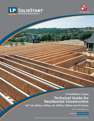
Limit States DesignLP SolidStart I-JoistsTechnical Guide forResidential ConstructionLPI 18, 20Plus, 32Plus, 36, 42Plus, 52Plus and 56 SeriesFloor & Roof ApplicationsPlease verify availability with the LP SolidStart Engineered Wood Products distributor in your area prior to specifying these products.
IntroductionLP SolidStart I-Joists are straighter and more uniform instrength, stiffness and size than traditional lumber, providinga strong, sturdy floor. We offer longer lengths so that ceilingsand floors can be designed with fewer pieces, saving timeon installation. Other advantages over lumber include lowermoisture content, which makes our I-Joists less likely to split,shrink, twist, warp or bow. This means reduced callbacks dueto fewer pops and squeaks.STRENGTH IN NUMBERSLP’s full range of SolidStart products are designed andmanufactured to install easily and work together to provide astrong, sound structure.For I-Joists, we combine laminated veneer lumber (LVL)COMPLIANT WITH MAJOR BUILDING CODESLP SolidStart I-Joists have been evaluated by CCMC foror finger-jointed sawn lumber flanges with a web of orientedcompliance with the National Building Code of Canada. Contactstrand board (OSB) to produce an I-shaped structural member.your local LP SolidStart Engineered Wood Products distributorThe webs allow plumbing and wiring to pass through withoutor visit www.lpcorp.com for the most current code reports.extra framing, while the flanges resist bending — ideal for longspans in floors, ceilings and roofs.LP SolidStart I-JOISTS ARE A BUILDING MATERIALWITH BUILT-IN ENVIRONMENTAL BENEFITS Made of engineered wood substrate, a renewable resourcewith a reduced environmental impact Raw material procurement targets small, fast growing trees In LP’s manufacturing process, no part of the log goesto waste Only low-emitting, safe resins are used as a binder Available in longer lengths, reducing the number of piecesneeded; this results in more efficient utilization of resources Can help you qualify for certification points in a numberof leading green building programs2LIFETIME LIMITED WARRANTYLP SolidStart Engineered Wood Products are backed by alifetime limited warranty. Visit LPCorp.com or call 1.888.820.0325for a copy of the warranty.
Table of ContentsProduct Specifications & Design Values . . . . . . . . . . . . . 4Web Stiffeners, Rim & Blocking, Nailing . . . . . . . . . . . . . 5Floor Span Tables. . . . . . . . . . . . . . . . . . . . . . . . . 6-9Uniform Floor Load (PLF) Tables . . . . . . . . . . . . . . . 10-11Uniform Roof Load (PLF) Tables . . . . . . . . . . . . . . . 12-13Roof Span Tables: Low Pitch (6:12 or less) . . . . . . . . . . 14-15Roof Span Tables: High Pitch (6:12 to 12:12). . . . . . . . . 16-17Load-Bearing Cantilever Tables . . . . . . . . . . . . . . . . 18-21Brick-Ledge Cantilevers . . . . . . . . . . . . . . . . . . . . 22-23Web Hole Specifications: Circular Holes . . . . . . . . . . . . 24Web Hole Specifications: Rectangular Holes . . . . . . . . .25Floor Details. . . . . . . . . . . . . . . . . . . . . . . . . . .26-27Roof Details. . . . . . . . . . . . . . . . . . . . . . . . . . . . 28Framing Connectors . . . . . . . . . . . . . . . . . . . . . . . . 29LP SolidStart Rim Board . . . . . . . . . . . . . . . . . . .30Handling and Storage Guidelines and Warnings . . . . . . . . 313
Product Specifications & Design ValuesLIMIT STATES DESIGN VALUESSeriesLPI 18LPI 20PlusLPI 32PlusLPI 36LPI 42PlusLPI 52PlusLPI 6"Factored 6019670169202037023625EI (x 2836321547802109260087411836689681301K (x .6930.6330.7470.8530.5490.6410.729Factored 804080NOTES:1. LP SolidStart I-Joists shall be designed for dry-use conditions only.Dry-use applies to products installed in dry, covered and well ventilatedinterior conditions in which the equivalent average moisture content inlumber will not exceed 15% nor a maximum of 19%.2. Moment and Shear are the factored resistances for standard load durationand shall be adjusted according to code.3. Moment resistance shall not be increased for repetitive member use.4. Deflection calculations shall include both bending and shear deformations.Deflection for a simple span, uniform load:42 22.5wL wLElKWhere: deflection (in)EI bending stiffness (from table)w uniform load (plf) K shear stiffness (from table)L design span (ft)Equations for other conditions can be found in engineering references.FACTORED REACTION AND BEARING RESISTANCESeriesLPI 18LPI 20PlusLPI 32PlusLPI 36LPI 42PlusLPI 52PlusLPI 56End Reaction Resistance1 (lbs)Minimum Bearing (1-1/2")Maximum Bearing 11-7/8"14"16"Interior Reaction Resistance1 (lbs)Minimum Bearing (3-1/2")Maximum Bearing Flange 720NOTESEXAMPLE:1. End and Interior Reaction Resistance shall be limited by the Flange Bearing Resistance or the bearing resistance of the support material,whichever is less.2. The Flange Bearing Resistance per inch of bearing length, is based on the compression perpendicular-to-grain of the I-Joist flange, accountingfor eased edges.3. To account for edge easing when determining the bearing capacity of the support material, subtract 0.25" from the flange width for the LPI 18,LPI 20Plus, LPI 32Plus, LPI 42Plus & LPI 52Plus, and subtract 0.10" from the flange width for the LPI 36 & LPI 56.4. Reaction Resistance, Flange Bearing Resistance and the bearing resistance of any wood support are for standard load duration and shall bereduced according to code for longer loading duration.5. Reaction Resistance and Flange Bearing Resistance may be increased over that tabulated for the minimum bearing length. Linear interpolationof the Reaction Resistance between the minimum and maximum bearing length is permitted. Bearing lengths longer than the maximum donot further increase Reaction Resistance. Flange Bearing Resistance and that of a wood support will increase with additional bearing length.6. The Interior Reaction Resistance may be calculated to a minimum bearing length of 3 inches, based on the 3-1/2" and 5-1/2" values.7. See page 5 for information on web stiffener sizes and nailing.Determine the stiffened end reaction capacityfor a 14" LPI 32Plus with 2" of bearing for anon-snow roof load and supported on an SPFwall plate (768 psi).1. Determine End Reaction (ER) w/Stiffeners:ER 2200 (2650 - 2200) * (2" - 1.5")/(4" - 1.5") 2290 lbs2. Determine Flange Bearing Resistance (FBR):FBR 1695 lb/in * 2" 3390 lbs3. Determine wall Plate Bearing Resistance (PBR):PBR 0.8 * 768 psi * (2.5" - 0.25") * 2" 2764 lbs4. Final End Reaction Resistance w/Stiffeners 2290 lbsPROFILE DETAILSLPI 18LPI 20PLUS & LPI 32PLUS2-1/2"3/8"49-1/2,"11-7/8"or 14"1-1/2"LPI 363/8"9-1/2,"11-7/8,"14" or 16"1-1/2"LPI "14" or 16"11-7/8,"14" or 16"1-1/2"LPI 52PLUS & LPI 563-1/2"1-1/2"7/16"11-7/8,"14" or 16"1-1/2"
Web Stiffeners, Rim & Blocking,page NailingheaderNOTES:WEB STIFFENER REQUIREMENTS1/8" min., 1" max. gap1/8" min., 1" max. gapConcentrated loadEnd support*1/8" min.,1" max. gapNails to be equallyspaced, staggered anddriven alternately fromeach face. Clinch nailswhere possible.1/8" min., 1" max. gapInterior orCantilever support** Refer to framing plan for specific conditions.1. Web stiffeners shall be installed in pairs – one to eachside of the web. Web stiffeners are always requiredfor the "Bird’s Mouth" roof joist bearing detail.2. Web stiffeners shall be cut to fit between theflanges of the LP SolidStart I-Joist, leaving aminimum 1/8" gap (1" maximum). At bearinglocations, the stiffeners shall be installed tight tothe bottom flange. At locations of concentratedloads, the stiffeners shall be installed tight to thetop flange.3. Web stiffeners shall be cut from APA Rated OSB(or equal) or from LP SolidStart LVL, LSL or OSB RimBoard. 2x lumber is permissible. Do not use 1x lumber,as it tends to split, or build up the required stiffenerthickness from multiple pieces.4. Web stiffeners shall be the same width as thebearing surface, with a minimum of 3-1/2."5. See Web Stiffener Requirements for minimumstiffener thickness, maximum stiffener heightand required nailing.WEB STIFFENER REQUIREMENTSSeriesLPI 18LPI 20PlusLPI 32PlusLPI 36LPI 42PlusLPI 52PlusLPI 56DepthMinimum ThicknessMaximum HeightNail Size*Nail /8"8-3/4"10-7/8"12-7/8"8-3/4"10-7/8"12-7/8"8d (2-1/2")8d (2-1/2")8d (2-1/2")8d (2-1/2")8d (2-1/2")8d (2-1/2")8d (2-1/2")10d (3")10d (3")10d (3")10d (3")10d (3")10d (3")10d (3")33334563333456* Nail Size is for common wire nails.RIM & BLOCKING CAPACITYSeriesLPI 18LPI 20PlusLPI 20PlusLPI 32PlusLPI 42PlusLPI 36LPI 52PlusLPI 56FLANGE FACE NAILINGDepthFactored VerticalResistanceSeriesCommon WireNail 02110253025302530338031002670LPI 18LPI 20PlusLPI 32PlusLPI 42PlusLPI 52Plus2-1/2"3"3-1/4"3-1/2"2-1/2"3"3-1/4"3-1/2"LPI 36LPI 56Minimum Nail Distanceoc 1/2"3"1-1/2"5"1-1/2"NOTES:1. Use only 2-1/2" or 3" nails when securing an LPI floor or roof joist to its supports.2. Power-driven nails shall have a yield strength equivalent to common wire nails of thesame shank diameter.NOTES:1. The Factored Vertical Resistance is the capacity inpounds per lineal foot of length (plf) and shall not beadjusted for load duration.2. Concentrated vertical loads require the addition ofsquash blocks. Do not use LPI rim or blocking to supportconcentrated vertical loads.3. Lateral load resistance for all series above is 260 plf butmay be limited by the connection details used. Do notexceed the Flange Face Nailing requirements above.5
Floor Span Tables: 19/32" OSB SheathingSPECIFIED FLOOR LOADS: 40 PSF LIVE LOAD, 15 PSF DEAD LOADTO USE:1.2.3.4.Select the appropriate table based on the floor system construction.Select the Simple Span or Continuous Span section of the table, as required.Find a span that meets or exceeds the required clear span.Read the corresponding joist series, depth and spacing.CAUTION: For floor systems that require both simple span and continuous span joists,it is a good idea to check both before selecting a joist. Some conditions are controlledby continuous span rather than simple span.Simple (single)Span ApplicationSpanContinuous (multiple)Span ApplicationSpanSpanSpan19/32" OSB SHEATHING NAILED ONLYSeriesLPI 18LPI 20PlusLPI 32PlusLPI 36LPI 42PlusLPI 52PlusLPI 14"16"11-7/8"14"16"No Direct Attached CeilingMaximum Simple SpansMaximum Continuous Spans12" oc16" oc19.2" oc12" oc16" oc19.2" '-6"21'-5"20'-4"26'-1"23'-10"22'-7"Direct Attached 1/2" Gypsum CeilingMaximum Simple SpansMaximum Continuous Spans12" oc16" oc19.2" oc12" oc16" oc19.2" 5"24'-2"22'-1"20'-11"26'-10"24'-7"23'-4"19/32" OSB SHEATHING GLUED & NAILEDSeriesLPI 18LPI 20PlusLPI 32PlusLPI 36LPI 42PlusLPI 52PlusLPI 14"16"11-7/8"14"16"DESIGN ASSUMPTIONS:No Direct Attached CeilingMaximum Simple SpansMaximum Continuous Spans12" oc16" oc19.2" oc12" oc16" oc19.2" 22'-2"24'-7"22'-9"21'-9"27'-3"25'-2"24'-1"1. The spans listed are the clear distance between supports. Continuous spans are based on thelongest span. The shortest span shall not be less than 50% of the longest span.2. The spans are based on uniform floor loads only, for standard load duration.3. These tables reflect the additional stiffness for vibration provided by a 19/32" OSB rated sheathing,or equal, attached as indicated (Nailed Only or Glued & Nailed) to the top flange.4. Live load deflection is limited to L/360 “bare joist.”5. Total load deflection is limited to L/240 “bare joist.”6. The spans are based on an end bearing length of at least 1-3/4" and an interior bearing length ofat least 3-1/2," and are limited to the bearing resistance of an SPF wall plate.6Direct Attached 1/2" Gypsum CeilingMaximum Simple SpansMaximum Continuous Spans12" oc16" oc19.2" oc12" oc16" oc19.2" ITIONAL NOTES:1. These spans have been designed to meet the Limit States Design andvibration requirements of the National Building Code of Canada.2. Web stiffeners are not required for any of the spans in these tables.3. Web fillers are required for I-Joists seated in hangers that do not laterallysupport the top flange.4. For conditions not shown, use the Uniform Floor Load (PLF) tables,LP’s design software or contact your LP SolidStart Engineered WoodProducts distributor for assistance.
Floor Span Tables: 23/32" OSBpageSheathingheaderSPECIFIED FLOOR LOADS: 40 PSF LIVE LOAD, 15 PSF DEAD LOADTO USE:1.2.3.4.Select the appropriate table based on the floor system construction.Select the Simple Span or Continuous Span section of the table, as required.Find a span that meets or exceeds the required clear span.Read the corresponding joist series, depth and spacing.CAUTION: For floor systems that require both simple span and continuous span joists,it is a good idea to check both before selecting a joist. Some conditions are controlledby continuous span rather than simple span.Simple (single)Span ApplicationSpanContinuous (multiple)Span ApplicationSpanSpanSpan23/32" OSB SHEATHING NAILED ONLYSeriesLPI 18LPI 20PlusLPI 32PlusLPI 36LPI 42PlusLPI 52PlusLPI 14"16"11-7/8"14"16"No Direct Attached CeilingMaximum Simple SpansMaximum Continuous Spans12" oc16" oc 19.2" oc 24" oc12" oc16" oc 19.2" oc 24" '-10"17'-4"16'-7"15'-10" "22'-10" "21'-4"20'-2"18'-5"17'-7"16'
page header 5 WEB STIFFENER REQUIREMENTS Series Depth Minimum Thickness Maximum Height Nail Size* Nail Qty LPI 18





![[MS-ADTS-Diff]: Active Directory Technical Specification](/img/1/ms-adts-170316-diff.jpg)
