Transcription
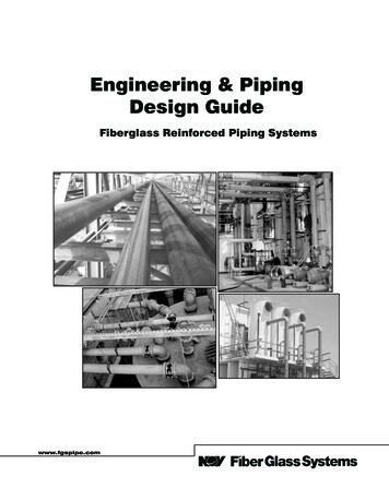
Engineering & PipingDesign GuideFiberglass Reinforced Piping Systemswww.fgspipe.com
I N T R O D UC T I ONNOV Fiber Glass Systems’ fiberglass reinforced epoxy andvinyl ester resin piping systems possess excellent corrosionresistance and a combination of mechanical and physicalproperties that offer many advantages over traditional pipingsystems. We are recognized worldwide as a leading supplierof piping systems for a wide range of chemical and industrialapplications.This manual is provided as a reference resource for someof the specific properties of our piping systems. It is not intended to be a substitute for sound engineering practices asnormally employed by professional design engineers.NOV Fiber Glass Systems has an international network ofdistributors and trained field personnel to advise on properinstallation techniques. It is recommended they be consultedfor assistance when installing the piping system. This notonly enhances the integrity of the piping system, but also increases the efficiency and economy of the installation.Additional information regarding installation techniques isprovided in the following installation manuals:Manual No. F6000Pipe Installation Handbookfor Tapered Bell & Spigot JointsManual No. F6080Pipe Installation Handbookfor Straight Socket Joints andButt & Wrap JointsManual No. F6300Pipe Installation Handbookfor Marine-Offshore PipingPIPING SYSTEMSEpoxy Resin Systems:· Z-Core (High Performance Resin)· Centricast Plus RB-2530· Centricast RB-1520· Green Thread · Marine-Offshore· Green Thread 175· Green Thread 175 Conductive· Green Thread 250· Green Thread 250 Conductive· Green Thread 250 Fire Resistant· Red Thread II· Red Thread II JP· Silver Streak (FGD Piping)· Ceram Core (Ceramic-lined Piping)· F-Chem (Custom Piping)· HIGH PRESSURE Line Pipe andDownhole Tubing*Vinyl Ester Systems:· Centricast Plus CL-2030· Centricast CL-1520· F-Chem (Custom Piping)* Available from NOV Fiber Glass Systems,San Antonio, TexasPhone: (210) 434-5043 · FAX: (210) 434-7543Web site: http://www.fgspipe.comGeneral Policy StatementNational Oilwell Varco has produced this brochure for general information only,and it is not intended for design purposes. Although every effort has been made tomaintain the accuracy and reliability of its contents, National Oilwell Varco in no wayassumes responsibility for liability for any loss, damage or injury resulting from the useof information and data herein nor is any warranty expressed or implied. Always crossreference the bulletin date with the most current version listed at the web site noted inthis literature.SAFETYThis safety alert symbol indicates an importantsafety message. When you see this symbol, bealert to the possibility of personal injury.iiNOV Fiber Glass Systems has developed a computer program specifically for our fiberglass products. This softwareprogram called Success By Design is available on ourweb site at http://www.fgspipe.com.
TA B LE O F CONTENT SIntroduction. iiPiping System Selection and Applications. 1SECTION 1 — Flow Properties.2Preliminary Pipe Sizing.2Detailed Pipe SizingA. Liquid Flow.2B. Loss in Pipe Fittings.4C. Open Channel Flow.5D. Gas Flow.5SECTION 2 — Above Ground System Design UsingSupports, Anchors & Guides.7Piping Support DesignA. Support Design.7B. Guide Design.8C. Anchor Design.9D. Piping Support Span Design.11SECTION 3 — Temperature Effects. 12System Design.12Thermal Properties and Characteristics.12Fundamental Thermal Analysis FormulasA. Thermal Expansion and Contraction. 13B. Anchor Restraint Load.13C. Guide Spacing.13Flexibility Analysis and DesignA. Directional Change Design.13B. Expansion Loop Design.14C. Expansion Joint Design.14D. Heat Tracing.15E. Thermal Conductivity.16F. Thermal Expansion in Buried Pipe. 16G. Pipe Torque due to Thermal Expansion. 16SECTION 4 — Pipe Burial.17Pipe Flexibility.17Burial AnalysisA. Soil Types.17B. Soil Modulus .18Trench Excavation and PreparationA. Trench Size.18B. Trench Construction.18C. Maximum Burial Depth.19D. Roadway Crossing.19Bedding and BackfillA. Trench Bottom.20B. Backfill Materials.20C. Backfill Cover.20D. High Water Table.20SECTION 5 — Other Considerations. 21A. Abrasive Fluids. 21B. Low Temperature Applications. 21C. Pipe Passing Through Walls orConcrete Structures. 21D. Pipe Bending. 21E. Static Electricity. 22F. Steam Cleaning. 22G. Thrust Blocks. 22H. Vacuum Service. 22I. Valves .22J. Vibration. 23K. Fluid (Water) Hammer.23L. Ultraviolet (U.V.) Radiation and Weathering. 23M. Fungal, Bacterial, and Rodent Resistance. 23SECTION 6 — Specificationsand Approvals. 24A. Compliance with National Specifications. 24B. Approvals, Listings, and Compliancewith Regulations. 24AP PENDICESAppendix A Useful Formulas.27Appendix B Conversions.30LI S T OF TABLESTable 1.0 Typical Applications.1Table 1.1 Flow Resistance K Values for Fittings. 4Table 1.2 Typical Liquid Properties.4Table 1.3 Typical Gas Properties.6Table 2.0 Minimum Support Width. 7Table 2.1 Saddle Length.8Table 4.0 Recommended Bedding and Backfill. 18Table 4.1 Nominal Trench Widths.18Table 6.0 ASTM D2310 Classification. 24Table 6.1 Classifying Fiberglass Flangesto ASTM D4024.25Table 6.2 Classifying Fiberglass PipeUsing ASTM D2310 andSpecifying Pipe Using ASTM D2996and D2997.26iii
P I P IN G S Y STEM S ELECTION AN D A PP LICATION SPIPING SYSTEM SELECTIONTYPICAL APPLICATIONSWhen selecting a piping system for a particular application,it is important to consider the corrosive characteristics ofthe media to which the pipe and fittings will be exposed, thenormal and potential upset temperatures and pressures ofthe system, as well as other environmental factors associated with the project. Fiberglass reinforced plastic (FRP)piping systems provide excellent corrosion resistance, combined with high temperature and pressure capabilities, allat a relatively low installed cost. NOV Fiber Glass Systemsengineers, using epoxy, vinyl ester, and polyester resins,have developed a comprehensive array of piping systemsdesigned to meet the most demanding application requirements. Piping systems are available with liners of varyingtype and thickness, with molded, fabricated, or filamentwound fittings, ranging in size from 1" to 72"(25 to 1800 mm)in diameter.Fiberglass piping is used in most industries requiring corrosion resistant pipe. FRP piping is used in vent and liquid applications that operate from -70 F to 300 F (-57 C to149 C). NOV Fiber Glass Systems piping systems use highgrade resins that are resistant to acids, caustics or solvents.Abrasion resistant materials can be used in the piping innersurface liner to enhance wear resistance to slurries. Table1.0 is a brief list of the many applications and industrieswhere fiberglass piping has been used successfully. SeeBulletin No. E5615 for a complete chemical resistance guide.Our piping systems can be installed in accordance with theASME B 31.3 piping code. Second party listings from regulatory authorities such as Factory Mutual, NSF, UL/ULC,and marine registrars are in place on several of these pipingsystems.TABLE 1.0 Typical Fiberglass Pipe Applications by IndustryINDUSTRYApplications ChemicalPetro MarineProcess Chemical p and Waste Water Mining andPaper TreatmentMetal RefiningAeration XBrine SlurryXBottom AshXChemical FeedXXXXXXColumn PipingXCondensate ReturnXXXXXXXXConduitXXXXCooling WaterXXXXDisposal WellsXXXXDownholeTubing& CasingXXXEffluent DrainsXXXXXXXXFire MainsXXXXXXXXFlue GasDesulfurization XGuttering &DownspoutsXXOily WaterXScrubber HeadersXXSeawater XXXXXXSlurryXVentsXXXXXXXWaterXXXXXXXXWaste TreatmentXXXXXXXXXBuried Gasoline X1XXX
SECTION 1. Flow PropertiesThe smooth interior surface of fiberglass pipe, combined withinside diameters larger than steel or thermoplastic pipe of thesame nominal diameter, yield significant flow advantages.This section provides design techniques for exploiting theflow capacity of fiberglass pipe.A. Liquid FlowFluid flow characteristics are very sensitive tothe absolute roughness of the pipe inner surface.The absolute roughness of NOV FiberGlass Systems piping is (0.00021 inches) 1.7 x10 -5 feet (1). This is less than 1/8 the average value for(non-corroded) new steel of (0.0018 inch) 15 x 10-5 feet(2).For ambient temperature water, the equivalent Manningvalue (n) is 0.009 and the Hazen-Williams coefficient is150.Preliminary Pipe SizingThe determination of the pipe size required to transport a givenamount of fluid is the first step in designing a piping system.Minimum recommended pipe diameters.The most commonly used pipe head loss formula is theDarcy-Weisbach equation.Clear fluidsEq. 1Eq. 5Where:Corrosive or erosive fluidsHf Pipe friction loss, ft(m)f Friction factorL Length of pipe run, ft (m)Eq. 2D Inner diameter, ft (m)V Fluid velocity, ft/sec (m/sec)g Acceleration of gravity, 32.2 ft/s2 (9.81 m/s2)Where:d Pipe inner diameter, inchThe friction factor is dependent on the flow conditions, pipediameter and pipe smoothness. The flow conditions aredetermined by the value of the Reynolds Number. Thereare four flow zones defined by the Reynolds Number; theyare laminar, critical, transitional and turbulent.Q Flow rate, gal/min (gpm)Sg Fluid specific gravity, dimensionlessp Fluid density, lb/ft3For laminar flow (Reynolds Number below 2,000), thefriction factor is calculated by Eq. 6Recommended maximum fluid velocitiesClear fluidsEq. 6Eq. 3Where Nr is the dimensionless Reynolds NumberCorrosive or erosive fluidsEq. 7Eq. 4Where:D Pipe inner diameter, ft (m)Where:V Fluid velocity, ft/sec (m/sec)V velocity, ft/secp fluid density,v lb/ft3Fluid kinematic viscosity, ft2/sec (m2/sec)Nr Reynolds Numberf Friction FactorTypical fiberglass piping systems are operated at flow velocities between 3 & 12 ft/sec.Detailed Pipe Sizing1Based on testing at Oklahoma State University in Stillwater, OK.2 CameronHydraulic Data, Ingersoll-Rand, Seventeenth Edition, 1988.2
For turbulent flow (Reynolds Number greater than4,000), the friction factor is calculated by the ColebrookEquation.Eq. 84,000 is considered the critical zone. Flow is neither fullylaminar or turbulent, although it is often assumed to belaminar for calculation purposes. Flow with Reynoldsnumbers between 4,000 and 10,000 is called the transitional zone where use of the Colebrook equation is considered more appropriate.These equations are quickly solved using a computerprogram, Success By Design, developed by NOV FiberGlass Systems specifically for our fiberglass products.Where:D Pipe inner diameter, inch (mm)e Absolute roughness, inch (mm)A demonstration of the Darcy-Weisbach and Colebrookequations for fiberglass pipe is shown in Figure 1.0.Nr Reynolds Number, unit lessf Friction Factor, unit lessThe flow with Reynolds numbers between 2,000 andFiberglass Pipe Pressure Loss Curves for WaterFigure 1
Fiberglass piping is used in most industries requiring cor-rosion resistant pipe. FRP piping is used in vent and liq-uid applications that operate from -70 F to 300 F (-57 C to 149 C). NOV Fiber Glass Systems piping systems use high grade resins that are resistant to acids, caustics or solvents.
