Transcription
CurieBot: Arduino 101 Mini Robot RoverCreated by John 1-mini-robot-roverLast updated on 2021-11-15 06:52:00 PM EST Adafruit IndustriesPage 1 of 64
Table of ContentsIntroduction3 Greetings Human Friend!3Unboxing CurieBot5 5677Kit ContentsArduino 101, USB Cable, & BatteriesRobot Chassis & Assembly ToolsPrototyping Parts and ComponentsAssembling and Wiring Your Robot Motors and Wheels and TiresLower ChassisTurn over the plateTurn over the plate againPrepare the Battery BoxesAdd the 9V Battery Box to the ChassisMiddle Chassis LayerMount the Arduino 101Solder the MotorShield HeadersServo PowerFinishing TouchesHow Your Robot Works: The Basics Board ManagerCode LibraryDC Motor TestLet's Get MovingCode for Your Robot MotorShield Library The Code78111212121516192428303536373839424343Driving Your Robot44Make Your Robot Autonomous48 Mounting the Sensors The Code4950Control Your Robot's Speed51 Using the Controller to Control Speed53Bling Out Your Bot54Servo Up Some Sweets57Sing a Song63 Adafruit IndustriesPage 2 of 64
IntroductionGreetings Human Friend!Welcome to CurieBot, your own mobile, customizable, and adorable, 32-bit,Bluetooth-enabled driving robot!Based upon our popular three-layer round robot platform, CurieBot brings somespecial sauce to the table -- delicious Arduino 101 sauce, that is! This powerfulboard comes in a familiar Arduino form factor, so you can use many of your favoriteshields, such as the included Adafruit MotorShield v2.Instead of the typical processor, this one is packing an Intel Curie 32-bit chip,which enables some very powerful on-board processing. The Arduino 101 also has a6-axis accelerometer/gyro, and that's not all -- it's got Bluetooth LE built directly ontothe board, which enables direct control of CurieBot right from your Bluetooth-capablephone or tablet! Adafruit IndustriesPage 3 of 64
Build and control your robot right away, and then begin exploring all of thepossibilities for modifications and expansion with this powerful new platform. Adafruit IndustriesPage 4 of 64
Unboxing CurieBotCurieBot is designed to introduce you to the joys of making with electronics. Wedecided to come up with a fun pack of parts that: Could introduce a beginner to making Teach soldering, electronics and programming skills Does not assume any prior experience Comes with enough fun parts that could be combined and adapted for monthsor years!Kit ContentsAfter a lot of thinking, here's what we came up with: Adafruit IndustriesPage 5 of 64
Arduino 101, USB Cable, & Batteries 1x Arduino 101 with Intel Curie (http://adafru.it/3033) the brains of your bot! It's aboard that combines the universal appeal of Arduino with the latesttechnologies - like the Intel Curie module (https://adafru.it/ueG), Bluetooth LEcapabilities, and a 6-axis accelerometer/gyro. 1x USB Cable - Standard A-B - 3 ft/1m (http://adafru.it/62) - use this to install newcode onto your Arduino 101 (from any computer) 1x 9V battery (http://adafru.it/1321) - this battery will power your Arduino 101 (butnot the motors) Adafruit IndustriesPage 6 of 64
4x AA Batteries (http://adafru.it/3349) - Use these to power your the motors ofyour super awesome little robotRobot Chassis & Assembly Tools 1x Three layer Robot Chassis Kit in Black (http://adafru.it/3244) - This kit givesyou everything you need to build the shell of a 2-wheel-drive Mobile PlatformRobot to help you channel your inner Mad Max. 1x Adafruit Motor/Stepper/Servo Shield v2 (http://adafru.it/1438) - Lets you driveup to 4 DC or 2 stepper motors- certainly enough motors to power the chassiskit!Prototyping Parts and Components 1x - Mini Solderless Breadboard - 4x4 points (http://adafru.it/2463) - Perfect fitfor your chassis kit. Add it to the prototyping area to upgrade your robot withmore sensors, lights, servos and beyond! 1x 9V Battery Holder with switch & plug (http://adafru.it/67) - Plugs into yourArduino 101's DC jack to power the CurieBot on and off with a flick of the switch 1x 4xAA Battery Holder w/ On/Off Switch (https://adafru.it/sfq) - A nice portablebattery holder for your robot's motor batteries. 1x Shield stacking headers for Arduino (http://adafru.it/85) - Solder these to yourMotorShield to allow access to all pins for further upgrades later! 1x Rubber Bumper Feet (https://adafru.it/dLG) - Helps keep the battery packssafe and secure 1x Foam tape rectangle - Helps mount the battery packs 4x Nylon 2.5mm pan screws - For mounting your Arduino 101 to the top deck ofthe robot (http://adafru.it/3299) 9x Nylon hexnuts - Also for Arduino 101 fastening (http://adafru.it/3299)Assembling and Wiring Your RobotThe wiring and assembly is pretty easy, and there is very little soldering required.You'll need a soldering iron and solder, diagonal cutters, a small screwdriver, and itwouldn't hurt to grab some pliers. You will also need a 9V battery, 4 x AA batteriesand a USB cable to upload code to the Arduino 101 board. Adafruit IndustriesPage 7 of 64
First, you'll assemble the robot chassis. All the parts needed for this are inside thebrown box with the 'Custom Black 2WD Robot extra layer' sticker on it.Motors and Wheels and TiresTo start, take the two motors, four longscrews, four nuts, and two black panels.Screw the two black panels onto themotors.The metal panels go on the side with thered and black wires coming out.Have the hex nuts on the metal panelside so they don't interfere with thewheel!The metal panels go on the side with the red and black wires coming out.Have the hex nuts on the metal panel side so they don't interfere with the wheel! Adafruit IndustriesPage 8 of 64
To make space for the 9V battery packlater, trim the excess off of the innermotor wheel shaft on each motor. Grabsome diagonal cutters (scissors or ahobby knife will work in a pinch) and trimoff about half the length of the motorwheel shaft that is on the same side asthe black plate you affixed.Take the two wheels, rubber treads, and2x small screws found in the same bag asthe wheels.Put the rubber treads on the wheels. Thisis a lot of fun! Adafruit IndustriesPage 9 of 64
Fit the wheels onto the white knob on themotors, they will snap nicely onto theoval center.Attach the wheels into place with the tinyscrews Adafruit IndustriesPage 10 of 64
Lower ChassisTake one of the black chassis layers. Allthree layers are identical.Align it on your table as shown on theleft. Note that the panel is notsymmetrical - look on the left to see thatrectangle cut out? Make sure it's alignedas you see here!Attach two of the brass standoffs ontothe black chassis layer.The standoffs should be screwed into thesecond set of holes from the outer edge meaning the two interior holes. Adafruit IndustriesPage 11 of 64
Turn over the plateAttach the white free-wheel into the exterior hole closest to the rectangular opening.The white free-wheel should be on the opposite side of the chassis of the standoff.Turn over the plate againTake your assembled wheels and fit them into the chassis layer.There are 2 slots on the black panels that you attached to your motor that should fitperfectly into the chassis layer.The metal front of the motor will be pointing toward the side of the chassis where youplaced your white freewheelPrepare the Battery BoxesFor this step, you will need the AA battery box, 4 x AA batteries, the 9V battery box, a9V battery the screwdriver, a sheet of 4 rubber bumpers, and double-stick foam tape. Adafruit IndustriesPage 12 of 64
First, open each battery box, grab out the screw, insert your batteries, and then screwthe boxes shut. Oh, and make sure you have the boxes switched to the off position.Now, take the 4 rubber bumpers and place them as shown in the picture below.Notice how the one bumper on the left side is not in the upper left corner. Important:don't throw away the leftover piece of bumper material, we are going to use that onthe next step. Adafruit IndustriesPage 13 of 64
Do not discard the leftover piece of bumper material.Flip the battery box over and place the scrap piece of the bumper material in themiddle. This will help hold the battery box nice and tight between the top and middleplate of your robot. Adafruit IndustriesPage 14 of 64
Add the 9V Battery Box to the ChassisCheck to see that the 9V box fits between the motors -- trim more of the inner shaftsif needed.Cut a small strip of double stick tape and press it onto the side of the battery box withthe 9V switch. Adafruit IndustriesPage 15 of 64
Place the battery box back in between the motors and stick it to the chassisMiddle Chassis LayerPlace the middle chassis layer onto robot, making sure to fit the motor tabs into theslots of the layer, then screw in the two brass standoffs. Adafruit IndustriesPage 16 of 64
Take a look at the image below and install the brass stand-offs in the same positions.You can insert the stand-off screws through the middle plate and hand tighten thestand-offs while putting a bit of pressure on the screw with your finger. Or, as a tip,you can screw in the stand-off screws with the flat end of the screwdriver, which canreach through the holes in the bottom plate. Adafruit IndustriesPage 17 of 64
Once you have the stand-offs in place as shown in the image above, let's place thebattery box in the correct spot as shown in the image below.Notice the battery box is lined up on the left side of the middle chassis plate. It shouldbe just in-between the upper left stand-off and the lower left stand-off (not touchingeither). This will make sure the on-off switch lines up just right in the hole of the topplate. Adafruit IndustriesPage 18 of 64
Mount the Arduino 101Next you mount the Arduino 101 to the top chassis plate. Before doing so, note theorientation of the plate, the end with the " " signs is the same as the other two plates,but the large rectangle cutout is flipped to opposite side compared to the bottomlayer. This is to accommodate the AA battery box switch.Use the black nylon screws and nuts to mount the Arduino 101 board to the top plate.Two of the Arduino mounting holes can be lined up with two of the plate holes andscrewed in. You'll mount the other two screws on the Arduino only to use as "feet" tokeep it from touching the board.Follow the animated assembly diagram for the specific sequence of screws and nutsto use on each hole. Adafruit IndustriesPage 19 of 64
Adafruit IndustriesPage 20 of 64
Adafruit IndustriesPage 21 of 64
Screw in the two screws and four nuts that'll protrude from the top of the middlechassis layer as seen below, then place the layer on top of the AA battery box.Screw the four brass standoffs into place with the small metal screws.Be sure to screw the two remaining black nylon screws into the Arduino 101 as seenhere, placing a one nut below and one nut above the board in each case as seen inthe animated diagram. Adafruit IndustriesPage 22 of 64
Place the Arduino 101 onto the top chassis layer, lining up the screws, then place theremaining nut onto the lower right screw to hold it in place. The upper left screw can'taccommodate a nut due to the header row, but the screw will prevent the board fromrotating.Route the wires up through the chassis layers for connecting them later to theMotorShield. Adafruit IndustriesPage 23 of 64
Solder the MotorShield HeadersNow it's time to solder the stacking headers into the Motor Shield. These will be usedto connect the MotorShield to the Arduino 101, while still allowing access to all pins forconnecting other sensor and components later.Solder the headers as seen below. You can follow this guide (https://adafru.it/ueH) formore details. Adafruit IndustriesPage 24 of 64
Once the headers are soldered in place, place the shield onto the Arduino 101.You will NOT use the power jumper that came with the MotorShield, so do notconnect it. Adafruit IndustriesPage 25 of 64
For this next step, you will need a set ofpliers. First, grab the long header pinsthat are attached together and breakthem into 2 sets of 2 header pins. Then,grab them in the pliers like shown here,and then slightly bend them so they looklike the next picture.Insert the two sets of bent headers into the female crimp cables from the motors, andthen into the MotorShield terminals M1 & M2, then tighten the screws down on them. Adafruit IndustriesPage 26 of 64
Make sure the battery packs are both turned off, then plug the 9V barrel plug into thejack on the Arduino 101.Then, insert the red wire from the AA battery pack into the power terminal on theMotorShield, and the black wire into the GND power terminal on the MotorShield,screwing them both down securely. Adafruit IndustriesPage 27 of 64
It is fine to skip this next step for normal use. However, if you think you'll beadding medium to large hobby servos to your CurieBot at some point, you canprepare the Motor Shield for it now.Servo PowerTo prepare for moderate to heavy servo use, you'll want to have servos draw from theMotorShield power supply, not the supply of the Arduino 101, otherwise you may runinto strange reset behavior when the Arduino power dips too low. Adafruit IndustriesPage 28 of 64
First, flip the MotorShield over and cut the power trace running to the servo powerpin.Then, solder a length of wire to the optional servo power pin (the "Opt. Servo" pinclosest to the large capacitor and reset button") on the MotorShield that can bescrewed into the power terminal. Adafruit IndustriesPage 29 of 64
Finishing TouchesThe CurieBot is nearly complete! To enable easy prototyping of small circuits (verysmall!) we've included a 4x4 baby breadboard. You can use the double stick tape toaffix it to the board, or for a more permanent attachment, trim down the breadboard'sfour legs with some diagonal cutters and then solder its four metal tabs into theMotorShield's prototyping holes.Some kits may include an alternate breadboard as seen here. Adafruit IndustriesPage 30 of 64
Adafruit IndustriesPage 31 of 64
Adafruit IndustriesPage 32 of 64
Adafruit IndustriesPage 33 of 64
Congratulations, you've built your robot! Adafruit IndustriesPage 34 of 64
That's it for the first part of getting your robot assembled and wired. Now, let's get thisrobot moving! On to the code!How Your Robot Works: The BasicsBefore we dig into the more complicated code, let's take a minute to break down thesimple motor controller code, and how it works to control your robot's motors.Before going any further, make sure you have a basic understanding of how toprogram and use an Arduino. Thankfully, we have a lot of great tutorials on how this Adafruit IndustriesPage 35 of 64
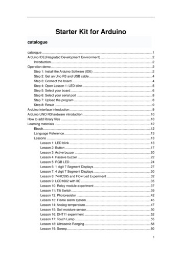
whole thing works. Click here to get started with Arduino (https://adafru.it/pcg), andthen come back to this guide to continue.Before going any further, make sure you have a basic understanding of how toprogram and use an ArduinoBoard ManagerTo use the Arduino 101 board, check the Arduino IDE Tools Board list and selectArduino 101.In case you don't see that board choice, you can click on Arduino IDE Tools Board Boards Manager. and then sort the list in the Boards Manager search bar with theword "101" and then update the AVR boards definition and install the 101 board asseen here. Adafruit IndustriesPage 36 of 64
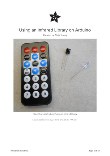
Code LibraryFor your robot to work correctly, you will need to install the MotorShield library. Toinstall libraries, we will use Arduino's handy library manager. Navigate to the librarymanager like shown in the screenshot below.Then, all you need to do is search for the library you want to install. For this robot,start by searching for 'Adafruit Motor Shield', you should see two options like this: Adafruit IndustriesPage 37 of 64
Under the Adafruit Motor Shield V2 Library, select the latest version from thedropdown, then click the install button.DC Motor TestNow that you have the library installed, let's open up the example sketch to try out theDC motors on your robot. You can find the example sketch DC Motor Test in the Arduino File Examples Adafruit Motor Shield V2 menu. Open it and upload it to yourCurieBot.Note this snippet of code below. It's instructing only Motor 1 to rotate.// Select which 'port' M1, M2, M3 or M4. In this case, M1Adafruit DCMotor *myMotor AFMS.getMotor(1);// You can also make another motor on port M2//Adafruit DCMotor *myOtherMotor AFMS.getMotor(2);When you see two forward slashes // in front of text, that is called commenting.Anything written after the // will be ignored by the Arduino. It is a way tocommunicate with whomever is reading your code.Place your robot on top of a cup or mug so the wheels are not touching the ground. Turn on AA battery holder switch to ON Select 'Arduino/Genuino 101' as the board under the Arduino Tools menu, and. Upload this code through the USB connectorNotice how just the one wheel is going forward, then backward. If you update thecode to this: Adafruit IndustriesPage 38 of 64
// Select which 'port' M1, M2, M3 or M4. In this case, M2Adafruit DCMotor *myMotor AFMS.getMotor(2);// You can also make another motor on port M2//Adafruit DCMotor *myOtherMotor AFMS.getMotor(2);With the motor port changed to 2, the other motor should now run. That is really thebasics of how we will go about controlling the robot.Let's Get MovingNow that you know how to make either motor go forward and backward with theexample sketch, let's learn the rest of the motor controller basics and write a sketch toget this robot moving. At the top of your sketch, you just need to call out both motors.To do this, you just need to uncomment the 'myOtherMotor' line of code by removingthe two forward slashes before the code. Then, reset the first motor to port 1 andkeep the second motor on port 2 like so:// Select which 'port' M1, M2, M3 or M4. In this case, M1Adafruit DCMotor *myMotor AFMS.getMotor(1);// You can also make another motor on port M2Adafruit DCMotor *myOtherMotor AFMS.getMotor(2);In this case, we have myMotor set to M1 , which is our right side motor, and myOtherMotor is set to M2 , our left side motor.Using the names myMotor , and myOtherMotor makes things really hard for us toremember which motor is which. So, we can simply change the variable name towhatever we want. Let's simply call them leftMotor , and rightMotor like this:// Set up the left motor on port M1Adafruit DCMotor *leftMotor AFMS.getMotor(1);// Set up the right motor on port M2Adafruit DCMotor *rightMotor AFMS.getMotor(2);Of course, now that we have changed the variable name, we need to replace anyinstance of myMotor with leftMotor , and myOtherMotor with rightMotor .Before we start driving forward, backward, or turning; we need to tell the motorcontroller how fast we want the motors to go. This is done using the setSpeedfunction. If we want to make both motors go full speed ahead, we would set themboth to 255 like this: Adafruit IndustriesPage 39 of 64
// Set the speed to start, from 0 (off) to 255 (max etSpeed(255);To make your robot go forward, all we need to do is tell each motor to go forward likethis:leftMotor->run(FORWARD); //LEFT MOTOR FULL STEAM AHEAD!rightMotor->run(FORWARD); //RIGHT MOTOR FULL STEAM AHEAD!All right, let's put this into a full sketch and give it a shot. For this sketch, Go aheadand upload this sketch to your robot. I have slowed down the speed for safety, butyou can update to whatever you want. Even though it is slowed down, don't forget toset your robot on a mug or a cup to keep the wheels off the ground./*CurieBot MotorShield test 01This is a test sketch for the Adafruit assembled Motor Shield for Arduino v2It won't work with v1.x motor shields! Only for the v2's with built in PWMcontrolFor use with the Adafruit Motor Shield include <Wire.h>#include <Adafruit MotorShield.h>#include "utility/Adafruit MS PWMServoDriver.h"// Create the motor shield object with the default I2C addressAdafruit MotorShield AFMS Adafruit MotorShield();// Or, create it with a different I2C address (say for stacking)// Adafruit MotorShield AFMS Adafruit MotorShield(0x61);// Set up the left motor on port M1Adafruit DCMotor *leftMotor AFMS.getMotor(1);// Set up the right motor on port M2Adafruit DCMotor *rightMotor AFMS.getMotor(2);void setup() {Serial.begin(9600);// set up Serial library at 9600 bpsSerial.println("Adafruit Motorshield v2 - Robot Test!");AFMS.begin(); // create with the default frequency 1.6KHz//AFMS.begin(1000); // OR with a different frequency, say 1KHz}void loop() {// Set the speed to start, from 0 (off) to 255 (max etSpeed(100);leftMotor->run(FORWARD); //LEFT MOTOR FULL STEAM AHEAD!rightMotor->run(FORWARD); //RIGHT MOTOR FULL STEAM AHEAD!} Adafruit IndustriesPage 40 of 64
Is your robot still not going forward? Be sure to flip the switch on your batterybox to 'on'Ok, so we have the robot going forward. To put the robot in reverse, you just need tochange FORWARD to BACKWARD . Turning is just as easy. To turn right, you just need toturn off the right motor, and go FORWARD with the left motor. This brings us to the nextbit of motor controller code you need to know, RELEASE . Instead of FORWARD , or BACKWARD , you can also use RELEASE . RELEASE is like pulling the plug on the motor. Itwill ignore speeds, and direction, and just stop what it is doing. The code forRELEASE looks like (RELEASE);If we take that to our sketch, we can now make the robot turn in circles by releasingthe right motor, and going forward with the left motor: Adafruit IndustriesPage 41 of 64
/*CurieBot MotorShield Test 02This is a test sketch for the Adafruit assembled Motor Shield for Arduino v2It won't work with v1.x motor shields! Only for the v2's with built in PWMcontrolFor use with the Adafruit Motor Shield include <Wire.h>#include <Adafruit MotorShield.h>#include "utility/Adafruit MS PWMServoDriver.h"// Create the motor shield object with the default I2C addressAdafruit MotorShield AFMS Adafruit MotorShield();// Or, create it with a different I2C address (say for stacking)// Adafruit MotorShield AFMS Adafruit MotorShield(0x61);// Set up the left motor on port M1Adafruit DCMotor *leftMotor AFMS.getMotor(1);// Set up the right motor on port M2Adafruit DCMotor *rightMotor AFMS.getMotor(2);void setup() {Serial.begin(9600);// set up Serial library at 9600 bpsSerial.println("Adafruit Motorshield v2 - Robot Test!");AFMS.begin(); // create with the default frequency 1.6KHz//AFMS.begin(1000); // OR with a different frequency, say 1KHz}void loop() {// Set the speed to start, from 0 (off) to 255 (max etSpeed(100);leftMotor->run(FORWARD); //LEFT MOTOR FULL STEAM AHEAD!rightMotor->run(RELEASE); //RIGHT MOTOR FULL STOP!}That just about covers the basics, now let's take this to the next level.Code for Your RobotTo take this robot to the next level, we are going to modify James De Vito's awesomecode for the similar Red Robot Rover (https://adafru.it/kBm). In his code, he hasmultiple control methods where you can either use the Bluefruit App controller or useyour phone's accelerometer to drive your robot. For this example, I am going tosimplify things and we will just use the control pad. This will free up the four auxiliarybuttons for some customization which we will cover later. Adafruit IndustriesPage 42 of 64
MotorShield LibraryFor this code to work, we will need to install a library. See the previous step on areally easy way to install this library using the Arduino Library manager.We will need the Adafruit MotorShield library. Learn more about this library anddownload it here. (https://adafru.it/t8A)You probably already have this installed if you followed the previous page but triplecheck now!The CodeOnce you have the libraries installed, you will want to download the latest rover code.Click the button below to download.Download Adafruit CurieBotsoftwarehttps://adafru.it/usAOnce the file has downloaded, unzip it and rename the folder from Adafruit CurieBotmaster to Adafruit CurieBotThen, place this folder in your Arduino sketches directory and open thesketch Ada CurieBot RC.There are a few other sketches included in the download which you'll use lateron in this guide.If you take a good look through this code, you will see it isn't so much morecomplicated than what we learned in the previous step. There is some complicatedcode that deals with the bluetooth connection to your phone (which we will use in thenext step). One neat feature we added is a way to slowly speed up the motors to full Adafruit IndustriesPage 43 of 64
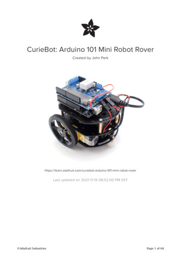
speed so it doesn't pop-a-wheelie when you take off going forward with this bit ofcode:// speed up the motorsfor (int speed 0; speed < maxspeed; speed 5) {L MOTOR->setSpeed(speed);R MOTOR->setSpeed(speed);delay(5); // 250ms total to speed up}We use a for loop to slowly ramp up the speed until it hits max speed. Learn moreabout for loops here (https://adafru.it/tb9).Driving Your RobotNow it is time to take control of your robot. We will be using the Adafruit Bluefruit LEConnect app. Go ahead and download it on your preferred device.Bluefruit app for iOShttps://adafru.it/dduBluefruit app for Androidhttps://adafru.it/f4GLoad up the Bluefruit LE Connect app, and the first thing you will see is a list ofavailable Bluetooth devices to connect to. Find the one that says Arduino 101 (orpossibly named CurieBot, depending on your mobile device), and tap the Connectbutton. Adafruit IndustriesPage 44 of 64
Once you connect, you will see a whole bunch of device information. At the bottom ofthe app, tap the Controller button. Adafruit IndustriesPage 45 of 64
On the next screen, you will see some advanced features of the app. For now, clickthe Control Pad link. Adafruit IndustriesPage 46 of 64
The Control Pad should load up, and if you turn your phone sideways, it will expand tofill the screen.Go ahead and use the arrows to drive your rover. Be careful, this little guy is fast! Besure to place it on the floor first! Adafruit IndustriesPage 47 of 64
Make Your Robot AutonomousWhile it is definitely neat to use your phone to control your robot, it is time to set yourlittle robot free. The first step in making your robot autonomous is to add proximitysensors so it can avoid obstacles.The simplest way to do this is to add a couple robot whiskers to sense when itphysically runs into a wall or object. You simply write some code to listen for when theswitch has been triggered, stop, turn around, and go forward again. These MicroSwitches with a wire are perfect for this.Micro Switch w/Wire - Three TerminalsMicro-switches are often found in arcadebuttons and joysticks but they're alsoreally handy in any kind of mechatronicsproject or when you need a basic sensor.They are always.https://www.adafruit.com/product/820While this is a great way to navigate around obstacles, I prefer to use a something abit more intelligent so my little robot doesn't actually have to run into things tonavigate. There are plenty of distance sensor options out there (there is a wholecategory of them (https://adafru.it/t8F) on the Adafruit shop), but the sensor I amgoing to use is the neat little IR sensor from from Sharp.Sharp GP2Y0D810Z0F Digital DistanceSensor with Pololu CarrierIf you're like me, you've always wanted asmaller and faster way to sense an objectbetween 2 and 10 centimeters away. Ifyou're really like me, you've wanted the.https://www.adafruit.com/product/1927The obvious benefit here is the size, but also the price. This little sensor will sense anobject about 10 centimeters away, and acts like a normal switch. There is a pin on the Adafruit IndustriesPage 48 of 64
board that is normally high and switches to low when it senses an object. Because ofthe small size, we can put two of these on our little robot.Mounting the SensorsThere are a ton of ways you can mount this sensor to your robot. The easiest waywould be to just a bit of double sided foam tape to stick it in place, but I decided tomake a super simple 3D printed mount.Click Here to Download the Mounthttps://adafru.it/t9bI used a couple M2.5 screws to secure the mounts to the robot (required a drill bit toclean up the holes in the 3D print). I wired up the left sensor to pin A0, and the rightsensor to pin A1. Adafruit IndustriesPage 49 of 64
The CodeThe code to make your robot take advantage of its new eyes is very straight forward.For now, we are going to focus on the Adafruit MotorShield library.Learn More About the AdafruitMotorShield Libraryhttps://adafru.it/t9c#include <Wire.h>#include <Adafruit MotorShield.h>#include "utility/Adafruit MS PWMServoDriver.h"// Create the motor shield object with the default I2C addressAdafruit MotorShield AFMS Adafruit MotorShield();// And connect 2 DC motors to port M1 & M2 !Adafruit DCMotor *L MOTOR AFMS.getMotor(1);Adafruit DCMotor *R MOTOR AFMS.getMotor(2);// And connect the Sharp distance sensorsint leftSensor A0;int rightSensor A1;void setup() {Serial.begin(9600);// set up Serial library at 9600 bpsSerial.println("Adafruit Motorshield v2 - DC Motor test!");pinMode(leftSensor, INPUT); // set up distance sensor pinspinMode(rightSensor, INPUT);AFMS.begin();// create with the default frequency 1.6KHz}void loop() {L MOTOR->setSpeed(200);R MOTOR->setSpeed(200);L MOTOR->run(FORWARD);R MOTOR->run(FORWARD);while (digitalRead(rightSensor) LOW){ Adafruit IndustriesPage 50 of 64
L MOTOR->setSpeed(100);R MOTOR->setSp
Mount the Arduino 101 Next you mount the Arduino 101 to the top chassis plate. Before doing so, note the orientation of the plate, the end with the " " signs is the same as the other two plates, but the large rectangle cutout is flipped to opposite side compared to the bottom