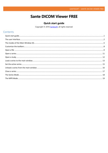
Transcription
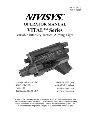
P/N 830-0055-0OSR 11-S-2324OPERATOR MANUALVITALTM SeriesVariable Intensity Tactical Aiming LightNivisys Industries LLC400 S. Clark DriveSuite 105Tempe, AZ 85281 USA480-970-3222 (tel)480-970-3555 (fax)info@nivisys.comwww.nivisys.comExport of the commodities described herein is strictly prohibited without a validexport license issued by the U.S. Department of State Office of Defense TradeControls prescribed in the International Traffic in Arms Regulations (ITAR) Title 22,Code of Federal Regulation, Chapter 1, Subchapter M, Parts 120-130.
Inside cover intentionally left blank.
OPERATORMANUALforVITALTM SERIESVariable Intensity Tactical Aiming LightTMVITAL-2TMVITAL-100ALL RIGHTS RESERVEDThis document contains information developed by Nivisys, LLC.It has been prepared to instruct Nivisys customers in the propercare and operation of the equipment respective to this document.Neither receipt nor possession thereof confers any right to reproduceor use, or disclose, in whole or in part, any such information withoutwritten authorization from Nivisys, LLC. 2011 Nivisys.Nivisys, LLC Rev. 25 Jan 2013i
This page intentionally left blank.Nivisys, LLC Rev. 25 Jan 2013ii
ADVISORY OVERVIEWThe following description categorizes the level of risk associated witheach cautionary statement displayed throughout the manual.WARNINGhighlights an operation orprocedure which, if not strictlyobserved, could result in injury to ordeath of personnel.CAUTIONhighlights an operation orprocedure which, if not strictlyobserved, could result in damage toor destruction of equipment or lossof mission effectiveness.NOTEhighlights an essential operation,procedure, condition or statement.Nivisys, LLC Rev. 25 Jan 2013iii
This page intentionally left blank.Nivisys, LLC Rev. 25 Jan 2013iv
LASER SAFETY DATAThis electronic product has been exempted from FDA radiation safetyperformance standards prescribed in the Code of Federal Regulations,Title 21, Chapter I, Subchapter J, pursuant to Exemption No.76EL-01DOD issued on July 26, 1976.Laser Safety Data*DescriptionLaser Power OutputVITAL-2VITAL-100.7mW max100mW maxLaser Beam DivergenceLaser Safety ClassNominal Ocular Hazard Distance(NOHD) for the unaided eyeLaser Wavelength0.5mR maxClass 1Class 3B0ft(0m)925ft(282 m)830 – 840 nm 20 nmDescriptionCQB ILLUMINATORCQB LED Output PowerLED Beam DivergenceLED Wavelength15 mW 5 mW20 ( )880nm 20nm*The above data is based on Laser Hazard Safety Analysis, Air ForceResearch Lab Human Effectiveness Directorate Optical Software. Datais based on a 10 second exposure for IR wavelength. All output powerreadings are maximum values at 73ºF (23ºC).Nivisys, LLC Rev. 25 Jan 2013v
This page intentionally left blank.Nivisys, LLC Rev. 25 Jan 2013vi
SAFETY INFORMATIONThe following section outlines general risks, safety precautions andwarnings associated with the safe use of a laser. Read the followingbefore any operation of the VITAL SERIES.WARNINGThere are eye and other hazardsassociated with the use of theVITAL Series. Safe operation ofthis product requires followingWarnings, Cautions and Notescontained in this Operator Manual.WARNINGA Laser Safety Officer (LSO) should beassigned to support operational andtraining activities using the VITAL. TheLSO should be adequately trained andprovide training IAW ANSI Z136.1-2007 (orlatest version).WARNINGAll personnel participating intraining or operations that involvethe use of lasers should comply withCommand / Organizational Unit andLSO guidance.Nivisys, LLC Rev. 25 Jan 2013vii
WARNINGIt is necessary and intended thatLaser Eye Protection (Night VisionDEVICES) be worn by the operatorwhen operating, maintaining,servicing, or testing the VITAL Series.WARNINGWhen in hoStile territory, operatethe VITAL with caution. Any personusing night vision DEVICES can detectthe IR source used in the VITAL.WARNINGNever view the beam directly onaxis through magnifying opticssuch as binoculars or telescopeswithoutappropriate safety filtersasmagnifying optics have the ability torefocus laser light and to increasethe nominal ocular hazard distance(NOHD).WARNINGUse of controls or adjustments orperformance of procedures otherthan those specific herein may resultin hazardous radiation exposure.Nivisys, LLC Rev. 25 Jan 2013viii
Table of ContentsAdvisory Overview iiiLaser Safety Data vSafety Information viiTable of Contents ixList of Figures xiList of Tables xiiiCHAPTER 1: GENERAL INFORMATION1-11.1Introduction 1-11.2Equipment Description 1-11.3Standard Kit Parts List1-21.4Standard Kit Parts Illustration1-31.5Optional Items List 1-41.6Optional Items Illustration1-41.7System Performance and Data1-51.8Nominal Ocular Hazard Distance (NOHD)1-7CHAPTER 2: PREPARATION FOR USE2-12.1Introduction 2-12.2Battery Precautions 2-12.3Battery Installation 2-22.4NVEC #16 Installation on an M162-32.5Attaching to a Weapon2-62.6Remote or Paddle Switch Installation2-7CHAPTER 3: OPERATING INSTRUCTIONS3-13.1Introduction 3-13.2Operating Precautions 3-13.3Controls and Indicators3-33.4Safe Operation 3-53.5Firing the Laser 3-53.6Beam Modes 3-6Nivisys, LLC Rev. 25 Jan 2013ix
Table of Contents (cont.)3.73.83.93.103.113.123.133.14Power Adjustment Knob3-7CQB Illuminator 3-8Elevation and Azimuth Adjusters3-8Preparing the VITAL for Zeroing3-9Zeroing the VITAL to a M-16/M-4using the NVEC#16 3-11Zeroing the VITAL to Any Weapon3-13IR Low Battery Indicator3-16Preparation for Storage3-17CHAPTER 4: MAINTENANCE INSTRUCTIONS4-14.1Introduction 4-14.2Battery Removal 4-14.3Cleaning the VITAL 4-14.4Cleaning the Optical Surfaces4-14.5Checking for Damage and Corrosion4-24.6 Preventive Maintenance Checks and Services (PMCS) 4-2CHAPTER 5: TROUBLESHOOTING 5-15.1Troubleshooting Procedures 5-1APPENDIX A: SPARE AND REPAIR PARTS LISTA-1A.1Introduction A-1A.2Contact Information A-1A.3Spare Part List A-1APPENDIX B: WARRANTY INFORMATION B-1Nivisys, LLC Rev. 25 Jan 2013x
List of -23-33-43-53-63-73-83-93-10DESCRIPTIONPAGEStandard Kit Parts Illustration1-3Optional Parts Illustration1-4Battery Installation 2-2NVEC#16 Installation, Steps 1-6 Exploded2-4NVEC#16 Installation, Steps 1-6 Completed2-4NVEC#16 Installation, Steps 7-8 Exploded2-5NVEC#16 Installation, Step 92-5NVEC#16 Installation, Step 102-6Weapon Mount Installation2-7Remote/Paddle Switch Installation2-8Paddle and Remote Switches2-8Controls and Indicators3-3Momentary Switch on Paddle and Remote Switches3-6ON/OFF/MODE Switch3-6Power Adjustment Knob3-8CQB Illuminator 3-8Elevation and Azimuth Adjuster Knobs3-9Neutral Adjustment Setting3-10Example Target for Zeroing Using the NVEC#163-11Example Target for Zeroing Any Weapon3-15IR Low Battery Indicator Location3-16Nivisys, LLC Rev. 25 Jan 2013xi
This page intentionally left blank.Nivisys, LLC Rev. 25 Jan 2013xii
List of AGEStandard Kit Parts List1-2Optional Items List1-4System Performance and Data1-5NOHD Summary 1-7Controls and Indicators3-4Beam Modes 3-7Preventive Maintenance Checks and Services4-2Troubleshooting 5-1Spare and Repair Parts ListA-1Nivisys, LLC Rev. 25 Jan 2013xiii
This page intentionally left blank.Nivisys, LLC Rev. 25 Jan 2013xiv
CHAPTER 1:GENERAL INFORMATION1.1Introduction:This manual provides operation and maintenance instructionsfor the VITAL. It also provides specifications and data onthe performance of the laser. The instructions will cover allvariants of the VITAL. To ensure the safety of the operator andthe correct operation of the weapon sight, it is recommendedthat this manual is read carefully in its entirety before anydeployment or field application.1.2Equipment Description:The VITAL SERIES are weapon mountable IR Pointers/Aimersand LED Illuminators. The IR light is invisible to the unaidedeye but fully visible to Gen II, Gen III image intensified nightvision devices.The VITAL-2 is a Class 1 aimer/pointer and has a maximumpeak output power of 0.7mW (eye- safe). The VITAL-100is a Class 3B IR aimer/pointer and has a maximum power of100mW. The illuminator is a LED IR light source with twointensity levels for close quarter battle target illumination.The VITAL incorporates a removable local control paddleswitch, conveniently placed for easy thumb activation. Aremote control switch is included with the VITAL. It is 12in(30cm) long. Custom lengths are available on request. The laseraimer can be activated on a momentary basis througheither the thumb switch or remote switch.Nivisys, LLC Rev. 25 Jan 20131-1
1.3Standard Kit Parts List:The standard VITAL kit comes with the items listed in thefollowing table.ItemPart No.DescriptionQty.1M002IRVITAL-2 Variable Intensity TacticalAiming LightVITAL-100 Variable IntensityTactical Aiming Light1M100IR2P-VIT-NVSoft Carrying Case23NVEC #161913 Rail Mount Kit(NSN: 5855-01-468-3689)14170-12Lens Cleaning Kit15SWCH510Remote Switch (Black)16SWCH512Paddle Switch (Black)17830-0055-0Operator Manual18580-0001-0AA Battery Alkaline29TARVIT1010 Meter Boresight Target110TARVIT2525 Meter Zero Target111SWCH514Remote Switch (Blue), VITAL-100only112SWCH515Paddle Switch (Blue), VITAL-100only113HC-VITALShipping/Storage Case, VITAL-100only114830-0056-0Quick Reference Guide1Table 1-1 Standard Kit Parts ListNivisys, LLC Rev. 25 Jan 20131-2
1.4Standard Kit Parts Illustration:The illustration below is provided for quick identification of thestandard parts of the VITAL kit.Figure 1-1 Standard Kit Parts IllustrationNivisys, LLC Rev. 25 Jan 20131-3
1.5Optional Items List:The VITAL is compatible with the following optional items andaccessories listed in the following table.ItemPart No.Description1BA-AABattery AA, Lithium2HC-VITALHard Shipping and Storage Case, VITAL-2Table 1-2 Optional Items List1.6Optional Items Illustration:The illustration is provided as a visual key to optional items thatcan be used with the standard VITAL.Figure 1-2 Optional Parts IllustrationNivisys, LLC Rev. 25 Jan 20131-4
1.7System Performance and Data:The table below lists the technical specifications and data of theVITAL system. The data contained herein is subject to changewithout notice.ITEMLIMITSElectricalVITAL-2Power SourceVITAL-1003.6 VDC MaximumBattery TypeAlkaline 1.5 VAA (2ea)Lithium 1.5 VAA (2ea)20 hrs25 hrsBattery Life @ 73ºF (23ºC)PhysicalOverall Dimensions5.5 x 2.75 x 2.25in(14 x 7 x 5.7cm)Weight (with batteries) andPaddle Switch7.8oz (221g)EnvironmentalOperation Temperature-32ºC to 51ºCStorage-57ºC to 71ºCLaserDescriptionLaser Power Output (max)@ 73ºF (23ºC)VITAL.7mWTable 1-3 System Performance and DataNivisys, LLC Rev. 25 Jan 20131-5100mW
ITEMLIMITSLaserLaser Safety ClassNominal Ocular HazardDistance (NOHD) for theunaided eyeVITAL-2VITAL-10013B0ft(0m)925ft(282m)Laser Beam Divergence (max)0.5mRLaser Wavelength830 20 nmDescriptionCQB ILLUMINATORCQB LED Output Power15mW 5mWLED Beam Divergence (max)LED Wavelength20 ( )880nm 20nmTable 1-3 System Performance and Data, (cont.)Nivisys, LLC Rev. 25 Jan 20131-6
1.8Nominal Ocular Hazard Distance (NOHD)The distance at which beam irradiance or radiant exposurebecomes equal to the maximum allowable exposure on thecornea. Care must be taken against laser exposure within thisdistance. However, it does not mean that continuously lookingat the laser beam at a distance longer than NOHD is safe or hasno hazardous influence.VITAL-100VITAL-2NOHD Summary for the VITAL SeriesType of ViewingNOHDUnaided0ft (0m)5 cm optics (7x50 binoculars)0ft (0m)8 cm optics (Tanks)0ft (0m)12 cm optics (Big Eyes)0ft (0m)Unaided925ft (282m)5 cm optics (7x50 binoculars)5249ft (1600m)8 cm optics (Tanks)9843ft (3000km)12 cm optics (Big Eyes)14436ft (4400)Table 1-4 NOHD SummaryNivisys, LLC Rev. 25 Jan 20131-7
This page intentionally left blank.Nivisys, LLC Rev. 25 Jan 20131-8
CHAPTER 2:PREPARATION FOR USE2.1Introduction:This section contains instructions for installing and attachingvarious components and accessories to the VITAL for operationunder normal conditions.2.2 Battery Precautions:WARNINGDo not mix alkaline and lithiumbatteries. Do not mix old and newbatteries. Do not mix brands ofbatteries. do not mix disposable andrechargeable batteries. Failure tofollow these instructions could resultin death, injury or imposition of longterm health hazards.WarningInspect batteries for bulging priorto use. If the battery shows signs ofbulging, do not use.WarningDO NOT HEAT, PUNCTURE, SHORT CIRCUIT,Incinerate, ATTEMPT TO RECHARGE OROTHERWISE TAMPER WITH THE BATTERIES.TURN OFF the VITAL IF the BATTERYCOMPARTMENT BECOMES UNDULY HOT. IFPOSSIBLE, WAIT UNTIL THE BATTERIES HAVECOOLED BEFORE REMOVING THEM.Nivisys, LLC Rev. 25 Jan 20132-1
CAUTIONObey the battery manufacturer’sdirections for battery disposal.2.3 Battery Installation:The electronic circuit is powered by two (2) AA battery cells.Install the batteries as follows.1. Release the battery catch by turning it in a clockwisedirection.2. Release the battery retainer arm by rotating it in a clockwisedirection.batterycapBATTERYRETAINER gure 2-1 Battery InstallationNivisys, LLC Rev. 25 Jan 20132-2
3.4.5.6.7.8.2.4Remove the battery cap by pulling the battery cap out of thebattery compartment.Observe the polarity symbols on the edge of the batterycompartment.Place two batteries into the compartment.Replace the battery cap.Replace the battery retainer arm.Turn the battery catch in a counter-clockwise direction untila stop occurs.NVEC #16 Installation on an M16:The VITAL is configured to attach to a MIL-STD-1913 railsystem. The standard VITAL kit includes the NVEC#16, whichis a rail that can be attached to a M16 style gun. To install theNVEC#16 perform the following.WARNINGensure the weapon is free andclear and that the weapon’s safetymechanism is switched to safe.1.2.3.4.5.6.Place spacer “A” between gas tube and barrel.Place upper clamp “B” between spacer tube and barrel.Place lower clamp “C” under barrel and align the holes inthe upper and lower clamps.Place mount body “D” over gas tube and align holes withthe clamp holes (spacer “A” fits into slot on mount body“D”).Install #6 screws and washers (I).With screws loose, slide assembly forward to the stop snugscrews but DO NOT TIGHTEN FURTHER.Nivisys, LLC Rev. 25 Jan 20132-3
DBACIFigure 2-2 NVEC#16 Installation, Steps 1-6 ExplodedFigure 2-3 NVEC#16 Installation, Steps 1-6 CompletedNivisys, LLC Rev. 25 Jan 20132-4
7.8.Replace hand guard “H” and rail “E” over mount posts “F.”Install and tighten flat head screws “G”.GEHFFigure 2-4 NVEC#16 Installation, Steps 7-8 Exploded9.Tighten screws “I”.iFigure 2-5 NVEC#16 Installation, Step 9Nivisys, LLC Rev. 25 Jan 20132-5
10. Install hand guard “J”.JFigure 2-6 NVEC#16 Installation, Step 102.5Attaching to a Weapon:Perform the following procedure to install the VITAL onto aMIL-STD-1913 rail system:WARNINGensure the weapon is free andclear and that the weapons safetymechanism is switched to safe.1.2.Open the lever of the mount perpendicular to the length ofthe VITAL.Place the VITAL on the MIL-STD-1913 rail system of theweapon.Nivisys, LLC Rev. 25 Jan 20132-6
3.4.Ensure that the mount is seated squarely on the rail.Close the lever of the mount in line with the length of theVITAL.lever CLOSEDFigure 2-7 Weapon Mount Installation2.6Remote or Paddle Switch Installation:The VITAL comes with two types of switches to be used to firethe laser. Both are installed using the same method. To install aremote or paddle switch into the VITAL perform the following.1. Locate the remote/paddle switch that will be used. Note thetwo tabs with metal strips on one side.2. Identify the switch receptacle on the VITAL located underthe windage and elevation adjusters.3. Ensure that the switch receptacle is free and clear ofmoisture and dirt.4. Insert the tabs of the remote/paddle switch into the VITALswitch receptacle.5. Ensure that the switch is fully seated into the switchreceptacle.Nivisys, LLC Rev. 25 Jan 20132-7
NoteTHE remote/paddle switch can only beinserted in one direction.TABSSWITCHRECEPTACLEPADDLESWITCHFigure 2-8 Remote/Paddle Switch InstallationFigure 2-9 Paddle and Remote SwitchesNivisys, LLC Rev. 25 Jan 20132-8
CHAPTER 3:OPERATIng instructions3.1Introduction:This chapter contains instructions for the safe operation of theVITAL under normal circumstances and environments.3.2Operating Precautions:WARNINGThere are eye and other hazardsassociated with the use of theVITAL Series. Safe operation ofthis product requires followingWarnings, Cautions and Notescontained in this Operator Manual.WARNINGA Laser Safety Officer (LSO) should beassigned to support operational andtraining activities using the VITAL. TheLSO should be adequately trained andprovide training IAW ANSI Z136.1-2000 (orlatest version).WARNINGAll personnel participating intraining or operations that involvethe use of lasers should comply withCommand / Organizational Unit andLSO guidance.Nivisys, LLC Rev. 25 Jan 20133-1
WARNINGIt is necessary and intended thatLaser Eye Protection (Night VisionDEVICES) be worn by the operatorwhen operating, maintaining,servicing, or testing the VITAL Series.WARNINGWhen in hoStile territory, operatethe VITAL with caution. Any personusing night vision devices can detectthe IR source used in the VITAL.WARNINGNever view the beam directly onaxis through magnifying opticssuch as binoculars or telescopeswithoutappropriate safety filtersasmagnifying optics have the ability torefocus laser light and to INCreasethe nominal ocular hazard distance(NOHD).WARNINGUse of controls, adjustments orperformance of procedures otherthan those specific herein may resultin hazardous radiation exposure.Nivisys, LLC Rev. 25 Jan 20133-2
3.3 Controls and Indicators:The controls and indicators for the VITAL are shown in Figure3-1 and are described in Table CATORPADDLE ORREMOTE Switch(paddle switchshown)SWITCHRECEPTACLEFigure 3-1 Controls and IndicatorsNivisys, LLC Rev. 25 Jan 20133-3
Control andIndicatorsFunctionsON/OFF/MODESWITCHThe ON/OFF switch is the master powerswitch and beam mode selector. The unit does notoperate until the momentary switch is activated.PowerAdjustmentKnobThe power adjustment knob is used to select thebest beam intensity level for the ambient lightingcondition.ElevationAdjusterAn elevation adjustment knob on top of the unitis used to adjust the strike of the bullet up anddown, during the zeroing process, at a rate of 0.4mR per click, 4.0cm at 100m.AzimuthAdjusterAn azimuth adjustment knob on the left side ofthe unit is used to adjust the strike of the bulletleft and right, during the zeroing process,at a rate of 0.4 mR per click, 4.0cm at 100m.Low BatteryIndicatorAn LED located on the rear of the housing thatglows amber to indicate low battery power.SwitchReceptacleReceives the paddle or remote switch.Paddle orRemote SwitchUsed to fire the laser.CQB IlluminatorUsed to illuminate areas in Close Quarter Battle.Table 3-1 Controls and IndicatorsNivisys, LLC Rev. 25 Jan 20133-4
3.4Safe Operation:Once the batteries are installed, do not point the laser towardany person within the NOHD. Night vision goggles willprovide protection by blocking the laser beam from directlyentering the eye but the goggles themselves may be damaged.Other than the enemy, do not intentionally illuminate anyonewith or without NVG within the NOHD, whether duringoperations or training. Refer to the section 1.8 for NOHDdistances.WARNINGNever view the beam directly onaxis through magnifying opticssuch as binoculars or telescopeswithout appropriate safety filtersas magnifying optics have the abilityto refocus laser light, increasingthe distance from the laser wherehazards may occur (Nominal OcularHazard Distance – NOHD). The NOHD forthe VITAL Series is listed in 1.8.WARNINGDo not point the laser at specularsurfaces (i.e. mirror-like).3.5 Firing the Laser:The VITAL fire button is a momentary switch, on both thepaddle and remote switch. It will only fire as long as it isdepressed. When the fire button is not depressed, the laseris not activated. To fire the VITAL perform the followingprocedure.1. Ensure the paddle or remote switch is correctly installed.Nivisys, LLC Rev. 25 Jan 20133-5
2.3.Turn the ON/OFF/MODE switch in a clockwise directionand select a beam mode.Press the momentary re 3-2 Momentary Switch on Paddle and Remote Switches3.6 Beam Modes:The VITAL features 5 different modes for beam output. Toadjust the beam mode, turn the ON/OFF/MODE switchclockwise from the OFF position. The switch will give audioand tactile feedback as each mode is selected. To ensurea specific mode, turn the ON/OFF/MODE switch until theselection indicator is in line with the printed mode icon.selectionindicatoron/off/modeswitchmode iconsFigure 3-3 ON/OFF/MODE SwitchNivisys, LLC Rev. 25 Jan 20133-6
The five printed mode icons are explained in the followingtable.VITAL BEAM MODESMode IconDescriptionON - SteadyON - Slow Pulse, 3HzON - Fast Pulse, 6HzON - Steadywith Low Power Close Quarter Battle (CQB)IlluminationON - Steadywith High Power CQB IlluminationTable 3-2 Beam Modes3.7Power Adjustment Knob:The power adjustment knob is used to regulate output power ofthe aimer beam. Lowering the power can lessen washout, haloeffect or excessive reflective luminance from close proximityto a target. The power adjustment knob is used in the followingmanner.1. Turn the knob counter-clockwise until a stop occurs. Thiswill slowly reduce output power by more than 90%.2. Turn the knob clockwise until a stop occurs. This willincrease the output power up to a maximum output powerlevel.NoteTHe Power knob must be held in placeto make a power level adjustment.After desired power is reached,release the knob.Nivisys, LLC Rev. 25 Jan 20133-7
PowerAdjustmentknobFigure 3-4 Power Adjustment Knob3.8 CQB Illuminator:The Close Quarter Battle (CQB) LED illuminator provides wideangle infrared light to aid night vision viewing in very darkconditions. The CQB illuminator can be set in the high or lowpower mode by the ON/OFF/MODE switch.CQBIlluminatorFigure 3-5 CQB Illuminator3.9Elevation and Azimuth Adjusters:Adjusters at top and left are used to zero the beam (dot) positionrelative to the bullet strike.1. An elevation adjustment knob on top of the unit is usedto adjust the strike of the bullet up and down, during thezeroing process, at a rate of 0.4mR per click, 4.0cm at100m.Nivisys, LLC Rev. 25 Jan 20133-8
2.An azimuth adjustment knob on the left side of the unit isused to adjust the strike of the bullet left and right, duringthe zeroing process, at a rate of 0.4mR per click, 4.0cm BFigure 3-6 Elevation and Azimuth Adjuster Knobs3.10Preparing the VITAL for Zeroing:This manual contains a comprehensive zero procedure to alignthe beam of the VITAL to the point of impact of the bullet. Itis recommended that the aim dot and the point of impact not becoincident but that they be offset on the boresight or zeroingtarget in the same relationship as they are mounted on theweapon. This will ensure the same aiming point to bullet strikerelationship at all engagement ranges. To zero the VITAL to theweapon perform the following.1. Install the VITAL onto the weapon rail with appropriatemomentary switch.NoteWhen Reinstalling The VITAL to theweapon, be sure to return it to theexact rail location for an accuratezero to weapon.Nivisys, LLC Rev. 25 Jan 20133-9
2.3.Set the power adjustment knob to its lowest setting byrotating it in a counter-clockwise direction.Achieve a neutral adjustment setting by turning eachadjuster clockwise until a stop occurs. Return the adjusterknobs approximately three rotations counter-clockwise untilthe white dot on the adjuster knob is visible through theadjuster tmentknobFigure 3-7 Neutral Adjustment SettingCAUTIONTo prevent jamming the adjustmentknobs, do not force the adjusters torotate past their end of travel.CAUTIONDo not use tools to turn adjusterknob.Nivisys, LLC Rev. 25 Jan 20133-10
3.11 Zeroing the VITAL to a M16/M4 using the NVEC#16:The equipment listed below is required to perform the followingprocedure.WARNINGensure the weapon is free andclear and that the weapon’s safetymechanism is switched to safe. M16/M4 rifle with NVEC#16 mount installed VITAL aiming light kit Stand or flat area to secure target (wall, clipboard, etc.) Weapons vise, sand bags or clamp Laser boresight with proper size bore mandrel Night vision system with day light cover 10m boresight target (TARVIT10) 82ft (25m) space away from personnel.Figure 3-8 Example Target for Zeroing Using the NVEC#16Nivisys, LLC Rev. 25 Jan 20133-11
NOTEUse the full size target supplied withthe VITAL kit when performing thefollowing zeroing procedure.1.2.3.4.5.6.Mount the VITAL on the weapon.Place the target on flat area at 33ft (10 m) from the weaponposition. Target area should be out of direct bright light, anindoor location is best.Lock the weapon in a weapon vise, clamp or stabilizeit with sand bags pointing in the direction of the target(CRITICAL).With the proper size mandrel, insert a laser boresight in thebarrel in accordance with laser boresight instructions.Adjust the weapon and/or target position to project the laserboresight beam to the laser boresight position on the target.Station a night vision equipped assistant near the target,WITH BACK TOWARDS IR LASER APERTURE.CAUTIOnKEEP DAYLIGHT COVER ON TO AVOID DAMAGETO NIGHT VISION DEVICE.7.Fire the VITAL and have night vision equipped assistantprovide directions to person at the weapon to adjust VITALbeam (elevation and azimuth).CAUTIONNight vision device should only beturned on long enough to mark thepaper.8.VITAL is boresight zeroed when IR laser is in the circle ofthe VITAL laser box crosshair on the target.Nivisys, LLC Rev. 25 Jan 20133-12
NOTEThis zeroing method will align theVITAL to be parallel to the line ofsight of the bore of the weapon.warningLive fire zeroing is recommended todetermine exact placementat knowndistances.NOTEThe VITAL will retain zero after ithas been removed and replaced onthe same weapon in the same slot onthe NVEC#16.WARNINGTHE VITAL must bere-zeroed whenever the mounting(base) bracket is removed andreplaced.3.12 Zeroing the VITAL to Any Weapon:After performing the dry boresighting of the VITAL series laseraimer to the weapon bore, it is recommended to conduct a livefire boresight at the 150m designated zero range. The procedureis as follows:1. Arrange a target at 150m range downrange.2. Adopt a secure and stable firing position.3. Don night vision goggles and switch ON.4. Activate the VITAL laser and bring the laser dot onto targetcenter.Nivisys, LLC Rev. 25 Jan 20133-13
5.6.7.8.Fire a group of 5 rounds, single shot, maintaining a steadyaim on the target centerClear weapon and switch to SAFETY.Check impact position of 5 rounds on the target, determinethe center of the shot group, or mean point of impact (MPI).If any adjustments are necessary, use the following table forMPI adjustments at 150m range:AzimuthDirection to moveadjusterMovement per clickClockwisemoves MPI downElevationClockwisemoves MPI right6cm (2.4in) at 150mTable 3-4 Live Fire Adjustments at 150m9.Repeat steps 2 through 8 until the center of the shot groupis located at or near the target center.If a full 150m range is not available, a 25m live fire boresightingmay be performed, using the supplied target 25m boresighttarget for 150m zero (TARVIT25).1.2.3.4.5.6.7.Arrange the TARVIT25 at 25m range downrange.Adopt a secure and stable firing position.Don night vision goggles and switch ON.Activate the VITAL laser and bring the laser dot ontodesignated rectangle aiming area.Fire a group of 5 rounds, single shot, maintaining a steadyaim on the target aiming area.Clear weapon and switch to SAFETY.Check impact position of 5 rounds on the target, determinethe center of the shot group, or mean point of impact (MPI).Nivisys, LLC Rev. 25 Jan 20133-14
8.If any adjustments are necessary, use the following table forMPI adjustments at 150m range:AzimuthDirection to moveadjusterClockwisemoves MPI downMovement per clickElevationClockwisemoves MPI right1cm (0.4in) at 25mTable 3-4 Live Fire Adjustments at 25m9.Repeat steps 2 through 8 until the center of the shot groupis located at or near the target center.TARVIT25 Rev. 23 MAR 111.5 L, 3.7 UAim Laser HereCenter of shot groupinside circle indicatesVITAL is boresightedto weapon for 150m.Figure 3-9 Example Target for Zeroing Any WeaponGrids are 1cm wide by 1cm high.Nivisys, LLC Rev. 25 Jan 20133-15
NOTEThe VITAL will retain zero after ithas been removed and replaced onthe same weapon in the same slot onthe NVEC#16.WARNINGTHE VITAL it must bere-zeroed whenever the mounting(base) bracket is removed from theVITAL and replaced.3.13IR Low Battery IndicatorThe VITAL features a low battery indicator located on therear of the unit near the power adjustment knob. It can only beviewed through a night vision device and will illuminate whenthe battery power is low, indicating that the batteries need to bereplaced.Figure 3-10 IR Low Battery Indicator LocationNivisys, LLC Rev. 25 Jan 20133-16
3.14Preparation for Storage:warningWhen not in use, store the VITAL Seriesin a Secure Area.1.2.3.4.5.6.Ensure that the ON/OFF/MODE switch is in the OFFposition.Remove batteries from the laser device.Inspect the battery compartment for corrosion or moisture.Clean and dry if necessary.Replace the battery cap.Remove any paddle or remote switch.NOTEPrior to placing VITAL into carryingcase, ensure the VITAL and case arefree of dirt, dust, and moisture.7.8.P
eye but fully visible to Gen II, Gen III image intensified night vision devices. The VITAL-2 is a Class 1 aimer/pointer and has a maximum peak output power of 0.7mW (eye- safe). The VITAL-100 is a Class 3B IR aimer/pointer and has a maximum power of