Transcription
FADAL MACHINING CENTERSGE FANUC 0i MCOPERATOR’S MANUALFADAL MACHINING CENTERS, LLCCorporate Office. phone (818) 407-1400 . fax (818) 407-0020Service / Parts. phone (818) 727-2100 . fax (818) 407-1004Programming Support . phone (818) 727-2100 . fax (818) 407-0061support@fadal.com20701 Plummer Street, Chatsworth, California 91311 USAMAN-0141 C
GE FANUC 0i MC OPERATOR MANUALThe content of this manual has been reviewed for accuracy.Differences may exist and we cannot guarantee that they are completely covered in this document.The information in this document is reviewed regularly and any necessary changes will beincorporated in the next revision. We welcome any suggestions for improvement.Material is subject to change without notice.This manual is for the exclusive use of Fadal Customers and Distributors. The reproduction,transmission or use of this document or its contents is not permitted without the expressed writtenpermission of Fadal Machining Centers. All rights, including rights created by patent grant orregistration of a utility, model or design, are reserved. Copyright 2002 Fadal Machining Centers.2006
FADAL MACHINING CENTERSTABLE OF CONTENTSTABLE OF CONTENTS . i1.0 POWER ON/OFF . 11.1 PRE-START CHECKING STEPS .21.1.1 OIL RESERVOIR .21.1.2 AIR PRESSURE .21.1.3 WATER RESERVOIR .31.1.4 FLOOD COOLANT .31.1.5 COOL POWER RESERVOIR .31.2 POWER ON/OFF .41.2.1 POWER ON .41.2.2 POWER OFF .51.2.3 ELECTRICAL CABINET DOOR .52.0 CNC CONTROL . 72.1 CONTROL LAYOUT .82.1.1 GE FANUC LCD .92.1.2 SOFTKEYS .92.1.3 GE FANUC MANUAL DATA INPUT .92.1.4 OPERATOR PANEL A .102.1.5 OPERATOR PANEL B .212.1.6 MANUAL PULSE GENERATOR .232.1.7 PCMCIA CARD PORT .232.1.8 RS 232 .232.1.9 BECON .233.0 CONTROL FUNCTION . 253.1 OPERATION MODE SELECTION .263.1.1 AUTO MODE .263.1.2 EDIT MODE .283.1.3 MDI MODE .293.1.4 REMOTE MODE .313.1.5 REF RETURN MODE .353.1.6 JOG MODE .373.1.7 HANDLE MODE .383.2 SAFETY FUNCTIONS .393.2.1 EMERGENCY STOP .393.2.2 DOOR OVERRIDE .393.2.3 WORKLIGHT .393.2.4 ALARM MESSAGE .393.3 TEST FUNCTION MODES .403.3.1 SINGLE BLOCk .403.3.2 BLOCK DELETE .403.3.3 OPTION STOP .40MAN-0141 CTABLE OF CONTENTSi
GE FANUC 0i MC OPERATOR MANUAL3.3.4 PROGRAM RESTART .403.3.5 MC LOCK .413.3.6 DRY RUN .413.4 SETUP MODES .423.4.1 FUNCTION KEY .423.5 TOOL OPERATION .433.5.1 DRUM FWD .433.5.2 DRUM REV .433.5.3 TOOL REL .433.5.4 T-COMMAND (TOOL NUMBER) .443.5.5 TOOL CHANGER COMMAND .453.6 AXIS DIRECTION SELECTION .563.6.1 X AXIS .563.6.2 X- AXIS .563.6.3 Y AXIS .563.6.4 Y- AXIS .573.6.5 Z AXIS .573.6.6 Z- AXIS .573.6.7 A AXIS .573.6.8 A- AXIS .573.6.9 RAPID OVERRIDE .573.7 SPINDLE OPERATION .583.7.1 SPINDLE STOP .583.7.2 SPINDLE CLOCKWISE .583.7.3 SPINDLE COUNTER-CLOCKWISE .583.7.4 MANUAL SPINDLE SPEED .583.7.5 M CODE / S CODE .583.7.6 SPINDLE SPEED RANGE .593.7.7 SPINDLE OVERRIDE .603.7.8 SPINDLE ORIENTATION .603.7.9 SPINDLE SPEED OVERRIDE .603.7.10 SPINDLE CALIBRATION .603.8 OPERATION CONTROL .613.8.1 FEED/RAPID/JOG OVERRIDE .613.8.2 MANUAL PULSE GENERATOR .623.8.3 HANDLE .623.9 EXECUTION FUNCTION .623.9.1 CYCLE START .623.9.2 FEED HOLD .634.0 M/C SET UP . 654.1 USER PREFERENCE .674.1.1 PROGRAM COORDINATE UNITS .684.1.2 T/H/D ALIGNMENT CHECK .694.1.3 TOOL CHANGE ADDS D/H OFFSETS .704.2 AXES SET UP .714.2.1 4TH (A) AXIS AMP FITTED .714.2.2 4TH (A) AXIS FITTED .714.3 AUTO TOOL CHANGER .724.3.1 TOOL CHANGE TYPE .72iiTABLE OF CONTENTS2006
FADAL MACHINING CENTERS4.4 TOOL LOAD MONITOR .734.4.1 POWER SET .744.4.2 TOOL TYPE .764.4.3 DATUM .774.4.4 LIMIT .784.4.5 ACTION .805.0 LENGTH SETTING . 815.1 SETTING TOOL ORIGIN POINT .825.2 SETTING TOOL LENGTH .845.3 TOOL DIAMETER/RADIUS SETTING .855.4 TOOL LENGTH DIAMETER/RADIUS ADJUSTMENT .866.0 DATUM SETTING . 876.1 DATUM EDGE LOCATION .886.1.1 X - AXIS LOCATION .886.1.2 Y - AXIS LOCATION .906.1.3 Z - AXIS LOCATION .916.2 COPYING OFFSETS .926.3 GLOBAL DATUM SHIFT .936.4 G92 POSITION SET .946.5 G92 POSITION SET CANCEL .977.0 CALCULATOR . 997.1 TRIANGLE SOLVER .1007.2 CIRCLE SOLVER .1017.3 SPEED AND FEED CALCULATOR .1028.0 QUICK CUT . 1078.1 SPINDLE CONTROL .1098.2 FEED CONTROL .1099.0 AICC FUNCTION . 1119.1 PROGRAMMING CONSIDERATIONS .1129.2 AICC PRECISION LEVEL DATA SCREEN .11410.0 TOOL MANAGEMENT . 11710.1 TOOL LIFE MANAGEMENT .11810.2 TOOL LIFE MANAGEMENT ACCESS .12110.3 ADD A TOOL .12110.4 ADD MORE TOOLS .12210.5 TOOL LIFE LIMIT SETTING .122MAN-0141 CTABLE OF CONTENTSiii
GE FANUC 0i MC OPERATOR MANUAL10.6 DELETE A TOOL .12310.7 DELETE ALL TOOLS .12410.8 RESET “TOOL LIFE EXPIRED” STATUS FOR THE TOOL .12410.9 RESET “TOOL LIFE EXPIRED” STATUS FOR ALL TOOLS .12510.10 TOOL SKIP .12611.0 MANUAL GUIDE I . 12711.1 MANUAL GUIDE I FUNCTION .12812.0 DATA I/O . 13312.1 DATA I/O FUNCTION .13413.0 COOLANT CONTROL . 13713.1 AUTO COOL .13813.2 FLOOD COOLANT .13813.3 MIST COOL .13813.4 COOLANT THROUGH SPINDLE (OPTIONAL) .13814.0 DATA SERVER. 13914.1 .13915.0 APPENDIX . 14115.1 M CODE LIST .14215.2 PLC ALARM LIST .14415.3 PLC MESSAGES .14715.4 G CODES .15015.5 FINAL BACK UP PROCEDURE .15015.6 COLD START POSITION SETUP PROCEDURE .15415.7 PROB .157INDEX . 159RENISHAW . 165ivTABLE OF CONTENTS2006
FADAL MACHINING CENTERS1.0MAN-0141 CPOWER ON/OFFPOWER ON/OFF1
GE FANUC 0i MC OPERATOR MANUAL1.1 PRE-STARTCHECKING STEPS1.1.1 OIL RESERVOIRExamine the oil levels. Both levels should be filled up to one inch from the top of thereservoir. The spindle oil reservoir may have oil in it for up to six months. The way lubeoil reservoir may run out of oil in one week.Figure 1-1: Spindle oil reservoir (optional)Figure 1-2: Way Lube Reservoir1.1.2 AIR PRESSUREThe inlet air must no exceed 120 PSI. This supplies air to tool IN-OUT cylinder and it isused for air blast during tool change. Visually inspect the air pressure gauge to verifythat it is set to at least 80-100 PSI. Air is used to operate: 2belt changespindle orientway lube pumpspindle air/oil pumpPOWER ON/OFF2006
FADAL MACHINING CENTERS spindle air seal tool changerFigure 1-3: Air Pressure1.1.3 WATERRESERVOIRVMC models release water collected in the water reservoir automatically. It is advisableto place an additional water trap in the air line going to the machine.1.1.4 FLOOD COOLANTReplenish the flood coolant level to avoid running out of coolant during execution of theprogram.Figure 1-4: Flood Coolant (Back side of the machine)1.1.5 COOL POWERRESERVOIR (OPT)MAN-0141 CExamine the cool power reservoir once a month.POWER ON/OFF3
GE FANUC 0i MC OPERATOR MANUALFigure 1-5: Cool Power Reservoir1.2 POWER ON/OFFFigure 1-6: Power Switch1.2.1 POWER ONTo turn the VMC ON:1. Turn the power switch CW onto ON position.2. Press the CNC control ON, [ I ] button on the operator panel.When the machine is powered on, it will enter the Fadal customscreen (Figure 1-7:).4POWER ON/OFF2006
FADAL MACHINING CENTERSFigure 1-7: Fadal Custom Screen.It is important you read the notes on the maintenance information display screen.3. Press [ Accept ] softkey.CNC will enter the System Configuration screen automatically.4. Press POS pushbutton on the MDI panel to enter position display screen ifneeded.1.2.2 POWER OFFTo turn the VMC OFF:1. Press Emergency Stop button.2. Press the CNC control OFF, [ O ] button on the operator panel.3. Turn the power switch CCW onto OFF position.1.2.3 ELECTRICALCABINET DOORTo lock the electrical cabinet door, push the power switch in and hold it hard until theclick sound indicating that the door is locked.To unlock the electrical cabinet door, turn the power switch CCW onto OPEN/RESETposition.MAN-0141 CPOWER ON/OFF5
GE FANUC 0i MC OPERATOR MANUAL6POWER ON/OFF2006
FADAL MACHINING CENTERS2.0MAN-0141 CCNC CONTROLCNC CONTROL7
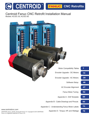
GE FANUC 0i MC OPERATOR MANUAL2.1 CONTROLLAYOUTLCDscreenBeconRS 232serial dataportPCMCIAcard portsoftkeysMDIpaneloperatorpanel Aoperatorpanel BMPGFigure 2-1: Fanuc 0i Control8CNC CONTROL2006
FADAL MACHINING CENTERS2.1.1 GE FANUC LCDFigure 2-2: GE Fanuc LCDLCD displays comprising screen indicating the operation and setup status of themachine.2.1.2 SOFTKEYSFigure 2-3: LCD softkeysThe softkeys are software controlled and screen-sensitive. Their functions change eachtime screen is displayed. Detailed description of the use of the softkeys is given in theGE Fanuc Operator Programming Manual supplied on CD-Rom with the machine.2.1.3 GE FANUCMANUAL DATAINPUTFigure 2-4: Manual Data Input Panel (US)MAN-0141 CCNC CONTROL9
GE FANUC 0i MC OPERATOR MANUALFigure 2-5: Manual Data Imput Panel (CE)Manual Data Input (MDI) panel is used for simple test operations. Detailed descriptionof the use of the MDI panel is given in the GE Fanuc Operator Programming Manualsupplied on CD-Rom with the machine.2.1.4 OPERATORPANEL AFigure 2-6: Operator Panel A (US)10CNC CONTROL2006
FADAL MACHINING CENTERSFigure 2-7: Operator Panel A (CE)Operator Panel A allows the operator to control machine operation. It is used inconjuction with the display screen and softkeys. This panel is equipped with 55pushbuttons. Each pushbutton has an associated Light Emitting Diode (LED) indicatorthat is ON when the associated pushbutton is active.Operator Panel A MANUAL DATAINPUT(MDI)MAN-0141 CCNC CONTROLFUNCTIONAuto (Memory) mode allows automaticoperation of part program selected fromprogram files registered in control’sprogram directory.For more detailed information see section 3.1.1Edit mode allows to enter and edit of partprograms stored in control’s part programdirectory. Part programs stored in optional DataServer or memory card inserted in PCMCIAcard slot are not available for editing. Programsmust be edited before loading the storagemedia.For more detailed information see section 3.1.2MDI mode allows to create and execute aprogram consisting up to 10 lines from the MDIpanel, which is in the same format as thenormal program. MDI mode is used for simpletest operation.For more detailed information see section 3.1.311
GE FANUC 0i MC OPERATOR MANUALOperator Panel A EEP FEED)SINGLE BLOCKBLOCKDELETEOPTION STOPREFERENCERETURNMODEMACHINELOCK12CNC CONTROLFUNCTIONIt is possible to perform machining while aprogram is being read in via reader/puncherinterface, or remote buffer. Operator can, also,perform machining with execution of theprogram in the memory card, which is installedin the memory card interface located on the leftside of the screen.For more detailed information see section 3.1.4Allows to execute part program block by block.Single Block mode is implemented to toggleON/OFF with press of pushbutton.Pressing Single Block switch starts the singleblock mode. When Cycle Start pushbutton ispressed in the Single Block mode, the toolstops after executing a single block in theprogram. Check the program in the SingleBlock mode by executing the program block byblock.Skip execution of program block (/). Multi levelBlock Skip is not supported. Block Delete isimplemented to toggle the ON/OFF with pressof pushbutton.Execution of the program will stop at M01 whenOption Stop pushbutton is ON. Operator needsto press Cycle Start pushbutton to restart theprogram. It does not effect the program whenthe Option Stop pushbutton is OFF.Opportunity to return all the axes to themachine zero position.For more detailed information see section 3.1.5Machine Lock enables execution of partprogram without axis motion, but M/S/Tcommand still is able to execute. Thispushbutton is for test purpose. Machine Lock isimplemented to toggle ON/OFF with press ofpushbutton.2006
FADAL MACHINING CENTERSOperator Panel A pushbuttonsBUTTON(US)BUTTON(CE)DESCRIPTIONDRY RUNPROGRAMRESTARTTOOL BROKENDRUMFORWARDDRUMREVERSEMAN-0141 CCNC CONTROLFUNCTIONDry Run feed rate forces program federate tofixed “dry run” rate to speed non-cutting testingof part programs. DRY RUN is implemented totoggle On/Off with press of pushbutton exceptAUTO and REMOTE mode.For more detailed information see section 3.3.4Program Restart provides the facility forrestarting a program at a chosen sequenceblock number following a program interruptionFor more detailed information see section 3.3.4Tool Broken function enables operator to marktool as damaged
10 CNC CONTROL 2006 GE FANUC 0i MC OPERATOR MANUAL Figure 2-5: Manual Data Imput Panel (CE) Manual Data Input (MDI) panel is used for simple test operations. Detailed description of the use of the MDI panel is given in the GE Fanuc Operator Programming Manual supplied on CD-Rom with t