Transcription
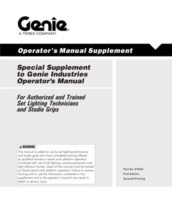
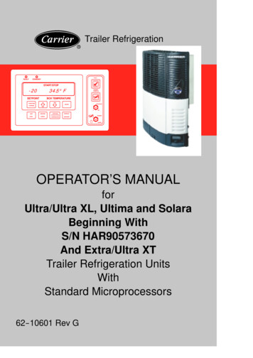
HW HCORPORATIONROPERATOR’S MANUALHWH COMPUTER-CONTROLLED725 SERIES LEVELING SYSTEMRFEATURING:Touch Panel Leveling ControlBI-AXIS Hydraulic LevelingStraight-Acting Power-Extend/Spring Retract JacksPilot Air DumpTwo Level Out Platform Lift Room ExtensionsOne Universal Straight Out Room ExtensionOne Single Cylinder Bed SlideInterface for Spyder Room ControlsRHWH COMPUTERIZED LEVELINGREXCESSSLOPEEXTENDAUTOLEVELNOT ETRACTRETRACTTRAVELMODEWARNING!UNDERSTAND OPERATOR’S MANUAL BEFORE USING. BLOCK FRAME AND TIRESSECURELY BEFORE REMOVING TIRES OR CRAWLING UNDER VEHICLE.HWH CORPORATION(On I-80, Exit 267 South)2096 Moscow Road Moscow, Iowa 52760Ph: 800/321-3494 (or) 563/724-3396 Fax: AN12
OPERATOR’S MANUALWARNING !READ THE ENTIRE OPERATOR MANUAL BEFORE OPERATING.BLOCK FRAME AND TIRES SECURELY BEFORE CRAWLING UNDER VEHICLE. DO NOT USE LEVELING JACKS ORAIR SUSPENSION TO SUPPORT VEHICLE WHILE UNDER VEHICLE OR CHANGING TIRES. VEHICLE MAY DROPAND/OR MOVE FORWARD OR BACKWARD WITHOUT WARNING CAUSING INJURY OR DEATH.KEEP ALL PEOPLE CLEAR OF VEHICLE WHILE OPERATING LEVELING SYSTEM OR ROOM EXTENSIONS.KEEP ALL PEOPLE CLEAR OF VEHICLE WHILE DUMPING AIR FROM THE VEHICLE’S SUSPENSION.DO NOT MOVE THE VEHICLE IF THE VEHICLE IS NOT AT THE PROPER RIDE HEIGHT. CONTACT MANUFACTURERTECHNICAL SERVICE FOR MOVING THE VEHICLE WHEN NOT AT THE PROPER RIDE HEIGHT.WEAR SAFETY GLASSES WHEN INSPECTING OR SERVICING THE SYSTEM TO PROTECT EYES FROM DIRT, METALCHIPS, OIL LEAKS, ETC. FOLLOW ALL OTHER APPLICABLE SHOP SAFETY PRACTICES.IMPORTANT: IF COACH IS EQUIPPED WITH A ROOM EXTENSION, READ ROOM EXTENSION SECTION BEFOREOPERATING LEVELING SYSTEM.HWH maintains technical and information services at 800-321-3494 or563-724-3396. Assistance is available Monday thru Friday from 8:00A.M until 5:00P.M. C.S.T.Technical and information service is also available on-line at www.hwh.com.MP14.001408APR10
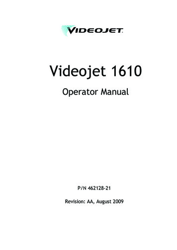
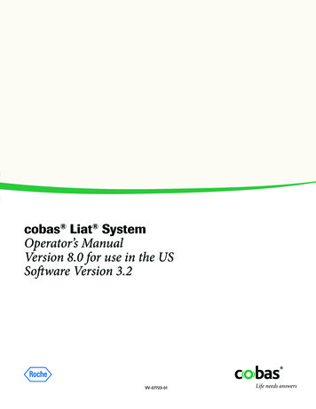
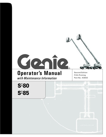
CONTROL IDENTIFICATION725 SERIES LEVELING SYSTEMCOMPUTER-CONTROLAUTO LEVELIndicator light"MANUAL DUMP"Button"EXCESS SLOPE"Indicator lightLOWER FRONTManual buttonRAISE FRONTManual button"AUTO LEVEL"ButtonHWH COMPUTERIZED LEVELINGR"NOT IN PARK"Indicator lightJACK DOWNIndicator light(4) redEXCESSSLOPEEXTENDAUTOLEVELSTOREIndicator lightNOT INPARK/BRAKEAUTO MANUALSTOREDUMP"AUTO STORE"ButtonEXTENDRAISE RIGHT SIDEManual buttonMANUALRETRACTRETRACTTRAVELMODECANCELLOWER RIGHT SIDEManual buttonWARNING!AUTO LEVEL/STORECANCEL ButtonUNDERSTAND OPERATOR’S MANUAL BEFORE USING. BLOCK FRAME AND TIRESSECURELY BEFORE REMOVING TIRES OR CRAWLING UNDER VEHICLE."TRAVEL MODE"Indicator lightLEVEL SENSINGIndicator light(4) yellowRAISE REARManual buttonRAISE LEFT SIDEManual buttonLOWER REARManual buttonLOWER LEFT SIDEManual buttonCONTROL FUNCTIONSCONTROL BUTTONS"CANCEL" BUTTON: Push this button to stopany leveling system operation."AUTO LEVEL" BUTTON: Push this button any time tostart the automatic leveling function."AUTO STORE" BUTTON: Push this button to retract allfour jacks at the same time."MANUAL DUMP" BUTTON: This is a manual button fordumping air from the vehicle suspension.EXTEND BUTTONS (UP ARROWS): These buttons willextend their respective jack pairs to lift the vehicle.RETRACT BUTTONS (DOWN ARROWS): These buttonswill retract their respective jack pairs to lower the vehicle.INDICATOR LIGHTSAUTO LEVEL INDICATOR LIGHT: This light will flashduring the automatic leveling function.STORE INDICATOR LIGHT: This light will flash duringthe automatic store function."EXCESS SLOPE" LIGHT: This indicator will light whenthe leveling system cannot level the vehicle.INDICATOR LIGHTS (CONTINUED)LEVELING LIGHTS: The four yellow indicating lights arelevel sensing indicators. When a yellow light is on, itindicates that its side, end, or corner of the vehicle is low.No more than two lights should be on at the same time.When all four yellow LEVEL lights are out, the vehicle islevel.WARNING LIGHTS: The four red lights surrounding theyellow level indicators are jacks down WARNING lights.They are functional only when the ignition is in the "ON"or "ACC" position, the system is on, and the jacks areextended approximately 1 inch."NOT IN PARK/BRAKE" LIGHT: This indicator will lightwhen the hand/auto brake is not set and the "AUTO LEVEL"button is being pushed."TRAVEL MODE" LIGHT: This indicator light will be onwhen the ignition is on, when the jacks are retracted andthere are no red WARNING lights on.MASTER "JACKS DOWN" WARNING LIGHT: This is alight mounted in the dash separate from the touch panel.It will be on when any one or more jacks are extendedand the ignition is "ON".BUZZER: This is a jacks down warning.It will sound if the master "JACKS DOWN"warning light is on.MP24.315117FEB21
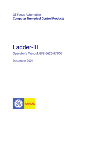
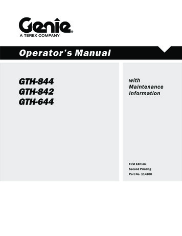
CONTROL IDENTIFICATIONPUMP RUN TIMEPUMP RUN TIMEPump motors used with HWH leveling systems and room extension systems come in 3 different diameters; 3", 3.7" and 4.5".Contact the vehicle manufacturer or HWH for help with identifying the motor size. It is important that any time the pumpruns for more than three minutes with a 3" motor; or six minutes with a 3.7" or 4.5" motor that the motor is allowedto cool for thirty minutes before continuing. Continuous operation of the pump motor without allowing the motorto cool can damage the motor. For cold weather information see "COLD WEATHER OPERATIONS" below.The HWH systems with a computer processor monitor the pump run time and will turn the pump off if the run time exceeds aspecified time. This time can vary with different systems. Due to available electronics or system design, the pump run timeprograms will also vary. Leveling systems and room extensions that are not controlled by a system processor have no pumprun time protection. DO NOT run the pump more than three or six minutes without allowing the pump motor to cool forthirty minutes.SYSTEM VARIATIONS FOR PUMP RUN TIMESome systems with rooms run the rooms separate from the system processor. These systems do not monitor pumprun time when operating the rooms. DO NOT run the pump more than three or six minutes without allowing thepump motor to cool for thirty minutes.Some systems can be turned back on immediately after the processor turns the pump off. DO NOT turn the systemback on or run the pump without allowing the pump motor to cool for thirty minutes.When operating some leveling systems manually or operating the room extensions, the pump will turn off and backon while pushing the control button when the pump run time has been exceeded. DO NOT continue without allowingthe pump motor to cool for thirty minutes.With some systems, when the processor has turned the pump off because the run time has been exceeded, powerto the HWH system must be turned off and back on before the system will operate. With motorized vehicles, turn theignition off and back on. With non-motorized vehicles, turn the master power switch for the HWH system off and backon. DO NOT continue without allowing the pump motor to cool for thirty minutes.Some HWH systems are equipped with a lighted reset switch.If the processor turns the pump off because the run time hasbeen exceeded, the light in the reset switch will turn on. Thesystem will not operate until the reset switch is pushed.DO NOT continue without allowing the pump motor tocool for thirty minutes.LIGHTED RESET SWITCHNo matter what HWH system is on the vehicle, the pump should not be ran for more than three minutes(3" motors) or six minutes (3.7" or 4.5" motors) without allowing the pump motor to cool for thirty minutes.Continuous operation of the pump motor without allowing the motor to cool can damage the pump motor.Contact HWH corporation to get specific information about the system in this vehicle.COLD WEATHER OPERATIONSHWH leveling and room extension systems are designed to function in cold weather down to 0 degrees Fahrenheit. Belowfreezing (32 degrees Fahrenheit) the jacks or rooms will operate slower than usual.For operation in temperatures dropping below -20 degrees Fahrenheit, it is necessary that the system is equipped with oildesigned for extreme cold weather application such as a synthetic oil. (Contact HWH for recommendations.)DO NOT run the pump motor continuously. It is important that any time the pump runs for more than three minuteswith a 3" motor; or six minutes with a 3.7" or 4.5" motor that the motor is allowed to cool for thirty minutes beforecontinuing. Continuous operation of the pump motor without allowing the motor to cool can damage the motor.Continuous operation of the pump with slow moving jacks or rooms in cold weather, without allowing the pump motor tocool will cause the pump motor to burn up and damage the pump assembly.MP25.999518MAR21
OPERATING PROCEDURESGENERAL INSTRUCTIONSMaintain adequate clearance in all directions for vehicle, roomextensions, awnings, doors, steps, etc. Vehicle may move inany direction due to jacks extending or retracting, settling ofthe jacks or the vehicle, equipment malfunction, etc.If parking on soft ground or asphalt paving, a wood block orpad should be placed under each jack.If the hand / auto brake is not set when the "AUTO LEVEL"button is pressed, the "NOT IN PARK/BRAKE" light willcome on. When the "AUTO LEVEL" button is released the"NOT IN PARK/BRAKE" light will go out. The AutomaticLeveling function will not start.WARNING:DO NOT MOVE THE VEHICLE IF ONEOR MORE JACKS ARE EXTENDED TO THE GROUND.Press the "CANCEL" button or turn the ignition switch"OFF" at any time to stop the operation of the system.Any time a hydraulic leveling process is interrupted, it isrecommended to retract the jacks according to the JACKRETRACTION Section and then restart the leveling process.PREPARATION FOR TRAVELIMPORTANT: Before traveling, the red jack warninglights must be off the "TRAVEL MODE" light must be onand the vehicle should be at the proper height for travel.If lights are not correct for travel, retract jack asdescribed in the JACK RETRACTION Section.If the jacks are retracted but a red "WARNING" light is litthe system needs to be serviced.Any room extension or generator slide should be fullyretracted before traveling.WARNING: DO NOT MOVE THE VEHICLE WHILETHE LEVELING JACKS ARE STILL IN CONTACT WITHTHE GROUND OR IN THE EXTEND POSITION. THISVEHICLE IS EQUIPPED WITH STRAIGHT-ACTING JACKS.MOVING THE VEHICLE WITH THE LEVELING JACKSEXTENDED CAN CAUSE SEVERE DAMAGE TO THEJACKS AND OR THE VEHICLE AND CREATE A DRIVINGHAZARD. DO NOT RELY SOLELY UPON WARNINGLIGHTS. IT IS THE OPERATOR’S RESPONSIBILITYTO CHECK THAT ALL JACKS ARE FULLY RETRACTEDINTO THE STORE/TRAVEL POSITION AND THEVEHICLE IS AT THE PROPER RIDE HEIGHT FORTRAVELING. CONTACT MANUFACTURER TECHNICALSERVICE BEFORE MOVING A VEHICLE THAT IS NOTAT PROPER TRAVEL HEIGHT.If the jacks cannot be retracted according to the JACKRETRACTION Section, retract the jacks according to theMANUAL JACK RETRACTION Section. The systemshould then be checked.NOTE: If the vehicle is parked or stored with the jacksextended for an extended period of time and the jacksfail to retract completely, extend the jacks back downto the ground then retract the jacks again.MP34.023207AUG13
OPERATING PROCEDURES725 SERIES LEVELING SYSTEMAUTOMATIC HYDRAULIC LEVELING (HWH TOUCH PANEL CONTROLS)1. Place transmission in the recommended position forparking the vehicle and set parking brake. Turn the coachengine off. Turn the ignition to the "ACCESSORY" position.NOTE: One or two yellow level indicator lights onthe leveling system touch panel can be on anytimethe vehicle ignition is in the ON or ACC. positionand the park brake is set.2. At this time, the operator may want to check the jacksand place a pad under each jack if the ground will notsupport the vehicle.WARNING: PRIOR TO PUSHING THE "AUTO LEVEL"BUTTON THE OPERATOR MUST BE SURE THAT ALLPERSONS AND OBJECTS ARE CLEAR OF THE VEHICLE.AIR WILL BE EXHAUSTED FROM THE VEHICLE SUSPENSIONAND THE VEHICLE WILL LOWER IMMEDIATELY AFTERTHE "AUTO LEVEL" BUTTON IS PUSHED.3. Press the "AUTO LEVEL" button one time.The AUTO LEVEL light will start to flash. The systemwill begin to dump air from the vehicle suspension. Afterapproximately 25 seconds, the leveling process will begin.IMPORTANT: During the Automatic Leveling procedures,pushing the "AUTO LEVEL", "AUTO STORE" or the"CANCEL" button on the HWH touch panel will stopthe automatic leveling function.When a jack extends approximately 1 inch, it’s individualred warning light on the touch panel will come on. Thetouch panel "TRAVEL MODE" light will go out. If theignition is in the ON position, the warning buzzer willsound.AUTO LEVEL SEQUENCE: During the automaticleveling sequence, after the system has extended theappropriate jacks to level the vehicle and has turnedthe yellow level indicator lights off, the system willthen stabilize the vehicle.STABILIZE SEQUENCE: The stabilize sequence is part ofthe Auto Level sequence. Each jack has a pressure switch.The switch will turn on when the jack extends to the groundand lifts the vehicle slightly. Jacks that have lifted the vehiclefor leveling should have pressure switches that are on.The stabilize procedure is a specific sequence where thecomputer checks the jack pressure switches. If the switchis on, the jack is already stabilizing the vehicle. If the switchis not on, the computer turns the pump and valve on for thatjack until the pressure switch turns on.The sequence starts with the right rear jack. If the pressureswitch is not on, the system will extend the jack as necessary.If the switch is on (or when it comes on) the system will checkthe left rear jack pressure switch, extending the jack if necessaryIf the left rear switch is on (or when it comes on), the systemwill recheck the right rear (extending if necessary) then recheckthe left rear (extending if necessary). After checking andrechecking both rear jacks, the system then checks the frontjacks. The system checks both front jacks at the same time.If either press
MANUAL RETRACT EXTEND CORPORATION HWH R Pilot Air Dump DUMP MANUAL Two Level Out Platform Lift Room Extensions One Universal Straight Out Room Extension One Single Cylinder Bed Slide Interface for Spyder Room Controls. WARNING ! READ THE ENTIRE OPERATOR MANUAL BEFORE OPERATING. BLOCK FRAME AND TIRES SECURELY BEFORE CRAWLING UNDER