Transcription
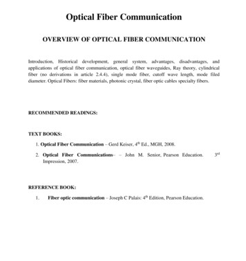
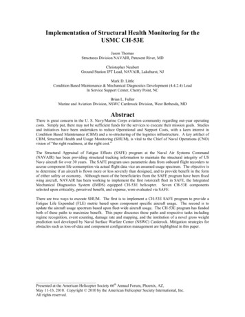
Space Flight Optical Fiber Activities & CapabilitiesMelanie N. OttW. “Joe” ThomesRick ChuskaFrank LaRoccaRob SwitzerNASA Goddard Space Flight CenterApplied Engineering & Technology Directorate, ElectricalEngineering Division,301-286-0127, melanie.n.ott@nasa.gov301-286-8813, hotonicsIMAPS 2008
Melanie N. Ott, Group LeaderApplied Engineering Technologies Directorate, Electrical Engineering DivisionRob Switzer, Frank LaRocca, W. Joe Thomes, Melanie Ott, Richard Chuska
COTS Technology Assurance Approach* Photonic Components for Space Systems, M. Ott, Presentation for Advanced Microelectronics and Photonics for SatellitesConference, 23 June 2004.
COTS Space Flight “Qualification”* Photonic Components for Space Systems, M. Ott, Presentation for Advanced Microelectronics and Photonics for SatellitesConference, 23 June 2004.
How Does the Photonics Group Go from Ideas to Flight?BASIC PRODUCT LIFE CYCLELesson: Thermal Workmanship Testing is a must for COTS flight hardware
Mercury Laser Altimeter 2001-2003Receiver telescopes focused into optical fiber assemblies that route to different detectors.The MLA is aboard MESSENGER on its way to Mercury!
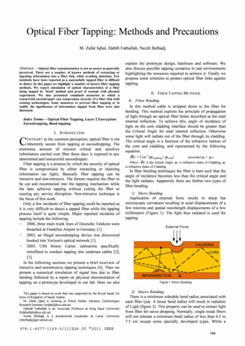
The Lunar Reconnaissance Orbiter; The Laser RangingMission and the Lunar Orbiter Laser Altimeter(HGAS) High GainAntenna SystemReceiver Telescopemounted on antennaand a fiber array toroute signal fromHGAS to LOLALunarOrbiter LaserAltimeter(LOLA)
NASA GSFC Fiber Optic Array Assemblies for the Lunar Reconnaissance OrbiterArray Side End Face Picture at200X magnificationLunar Orbiter Laser Altimeter (LOLA) AssembliesDescription: 5 Fiber Array in AVIM PM on Side A,Fan out to 5 individual AVIM connectors Side BWavelength: 1064 nmQuantity 3 Assemblies Max 0.5 m longEnd Face Picture of both assembly ends at200X magnificationLaser Ranging (LR) for LRO AssembliesDescription: 7 Fiber Array on both Sides in AVIMPM ConnectorWavelength: 532 nmQuantity 9 Assemblies 1 to 4 m long each
Laser Ranging on Lunar Recon Orbiter 2006-2008GSFC Photonics Group Quality DocumentationDocument NameCM DocumentationNumberThermal Pre-conditioning on Flexlite 200/220 µm fibers for flight applicationLOLA-PROC-0137Preconditioning Procedure for AVIM Hytrel Boots for LOLA fiber opticDiamond AVIM PMassembliesKit Pre-Assembly InspectionLOLA-PROC-0138Ferrule Polishing & Ferrule/Adapter Matching ProcedureLOLA-PROC-0139Assembly and Termination Procedure for the Laser Ranging Seven Fiber CustomPM Diamond AVIM Array Connector for the Lunar Reconnaissance OrbiterLOLA-PROC-0112Compression Test Procedure for Fiber Optic ConnectorLOLA-PROC-0141Active Optical Power Optimization Procedure for The Laser Ranging Optical FiberArray AssembliesLOLA-PROC-0110Laser Ranging Fiber-Optic Bundle Optical Test ProcedureLOLA-PROC-0107Insertion Loss Measurement Procedure for The Laser Ranging Optical Fiber ArrayBundle AssembliesLOLA-PROC-0111Mating of Two LR 7-Fiber Optical Fibers Using Cleanable AdapterLOLA-PROC-0142Cutting Back The Kynar Strain Relief For IntegrationLOLA-PROC-0143Fiber Optic Bundle Inspection and Insertion Loss MeasurementLOLA-PROC-0148LOLA-PROC-0104All manufacturers need in-depth quality documentation
LRO Integration HGAS
Lunar Recon. Orbiter - LRT & HGAS
LRO Integration @ IM Deck
LOLA Integration & Laser Ranging TestingMel Integrating the flight hardware to LOLA during Oct. and Nov 2007Team testing the flight Laser Ranging Assemblies in the Photonics Lab
Mars Science Lab, Chem CamAVIM connectors – Flexlite Cable
MSL CM DocumentationDocument NameCM Document NumberOptical Cable Inspection562-PHOT-QAD-MSL-FON1482-INSPCable Thermal Pre-Cond562-PHOT-QAD-MSL-THERM-PCPolymers Degas562-PHOT-WOA-MSL-BOOTS (Hytrel degas @ Materials)Mission Survival Radiation Total DoseTesting562-PHOT-QAD-MSL-RAD (12-day worst-case cobalt60 radiation testing)Mission Survival Vibration Qualification562-PHOT-QAD-MSL-VIBE (7.9grms to 14.4grms step-up vibration on selected samples)Mission Survival Thermal Cycling Testing562-PHOT-QAD-MSL-THERM-CYCLE (100 cycles including planetary bake-out)FC Cable Manufacturing (non-flight)AVIM Cable Manufacturing (non-flight)AVIM Cable Manufacturing (flight-like)562-PHOT-QAD-MSL-MAN-92 (Patch Cables)562-PHOT-QAD-MSL-MAN-92-332 (Prototype Development)562-PHOT-QAD-MSL-MAN-332-EM (Eng Models)AVIM Cable Manufacturing (FLIGHT)562-PHOT-QAD-MSL-MAN-332-FM (FLIGHT and FLIGHT Spares)Insertion Loss Testing (All-Cables)562-PHOT-QAD-MSL-INS-92-332 (Insertion Loss testing Pre and Post all tests)Non-flight Cable Workmanship Testing562-PHOT-QAD-MSL-WKM-92-NONFL (Non-flight workmanship)FLIGHT Workmanship Testing562-PHOT-QAD-MSL-WKM-332-FLIGHT (FLIGHT workmanship)MSL CABLE TRAVELERGSFC-PHOTONICS CABLE TRAVELER REV 080101Engineering Documents ReviewGSFC-PHOTONICS ENGINEERING DOCUMENT REVIEW (Lead Manufacturing, ProjectLead)Pre-Shipment Inspection ChecklistGSFC-PHOTONICS PRE-SHIPMENT PROCEDURE CHECKLISTCable Packing Procedure ChecklistGSFC-PHOTONICS PACKING PROCEDURE CHECKLIST
2008 New Capability19 Fiber Arrays with Linear to Bundle Mapping
Express Logistics Carrier, Connection to ISSAVIM connectors – Flexlite CableFiber Optic Flight Assemblies for Space Photonics Transceiver Inspection, Preconditioning,Manufacturing, Testing and Workmanship Procedure, (As Run Format)ELC PROC 000400
Qualification Testing of the MTP for Sandia National Labs1998 - 2008
Materials IssuesShuttle Return to Flight: Construction AnalysisOptical Fiber Pigtailed Collimator AssembliesLightpath: pigtailed fiber to collimator lens and shellGSFC: upjacket (cable), strain relief and termination, AVIMS, PC, SMMaterials & Construction Analysis Non compliant UV curable adhesive for mounting lenses to case- Solution 1: replace with epoxy, caused cracking during thermal cycling- Solution 2: replace with Arathane, low glass transition temp. adhesiveLesson: coordinate with adhesives expert, care with adhesive changes. Hytrel, non compliant as an off the shelf product (outgassing, thermal shrinkage)- Thermal vacuum preconditioning (145 C, 1 Torr, 24 hours)- ASTM-E595 outgas test to verify post preconditioning.- Thermal cycling preconditioning (30 cycles, -20 to 85 C, 60 min at 85 C)
Materials Issues: Shuttle Return to FlightLaser Diode AssembliesFitel: laser diode pigtailsGSFC: Upjacket (cable), strain relief, termination, AVIMS APC SMFitel uses silicone boot, non-compliant!Too late in fabrication process, schedule considerations to preprocess.Cable: Thermal preconditioning, 30 cyclesHytrel boots: Vacuum preconditioning, 24 hoursKynar heat shrink tubing, epoxy: approved for space use.Post manufacturingdecontamination of entireassembly requiredLaser diode rated for 85 Cprocessing performed at70 C
Environmental Parameters: VibrationLaunch vehicle vibration levels for small components (GEVS)(based on box level established for EO-1) on the “high” side.Frequency (Hz)Protoflight Level200.052 g2/Hz20-50 6 dB/octave50-8000.32 g2/Hz800-2000-6 dB/octave20000.052 g2/HzOverall20.0 grms3 minutes per axis, tested in x, y and zLesson: Better to test higher than find out at the last minute your profile is too low
Thermal EffectsThermal stability is dependent on;Cable constructionOuter diameter (smaller more stable).Inner buffer material (expanded PTFE excellent).Extrusion methods (polymer internal stresses).Preconditioning60 cycles usually keep shrinkage less than 0.1%Survival limits (hot case) is used for cycling.Cut to approximate length prior.TerminationFerrule – Jacket isolation necessary.Polishing methods (especially at high power).
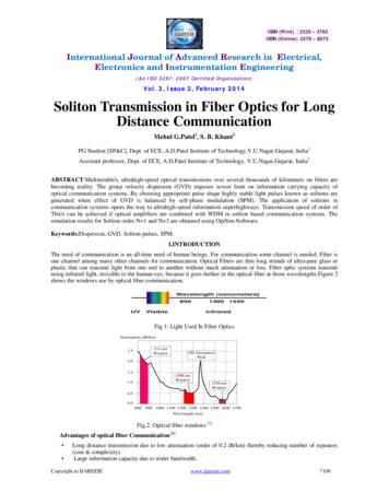
ISS Cable Candidates; Thermal Screening for ShrinkagePrequalification: Thermal Induced Shrinkage Testing onFiber Cable CandidatesFO Cable Shrinkage vs. Thermal Cycle1.2%General Gable OC-1260W.L. Gore GSC-13-83034-00Flexlite 100/140 FON-1012Flexlite 300/330 FON-1174Relative 505560# of CyclesThermal range –50 C to 120 C, hour soak times at extremesbased on current specifications of cablesBecause fluoropolymers have thermal shrinkage issues.
ISS Cable Candidates; Thermal Pre Qual, -121 CManufacturerPart NumberFiber TypeThermal RangeW.L GoreFON1012,FLEX-LITE OFS BF05202 100/140/172-55 to 150 CGeneral CableOC-1260Nufern (FUD-2940)-65 to 200 C100/140/172W.L GoreGSC-13-83034-00 1.8mmNufern (FUD-3142)-55 to 125 C62.5/125/245The above cable candidates were tested for 16 hours at -121 C
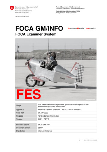
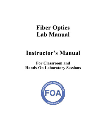
ISS Cable Candidates; Thermal Pre Qual, -121 C9 metersThermally Induced Loss ofGeneral Cable's OC-1260 100/140 Cable,W.L. Gore's GSC-13-83034-00 62.5/125 & FON 1012 (100/140) Cables(1310nm @ -121C)4.54.0Thermally Induced IL (dB)3.5OC-1260 ILGSC-13-83034-00 IL3.0FON-1012 (100/140)2.52.01.51.00.50.001233456788Time (hrs)91011121313141516
LRO Laser Ranging Cold Gimbal Motion Life TestingGimbalsWindow inside gimbal;Flexlite cable insideGimbals w/ single flexlite in thermal chamberWindow inside gimbal;Bundle cable inside.Gimbals w/ bundle in thermal chamber
LRO Laser Ranging Bundle Cold Gimbal Motion Testing ResultsEnd of Test, relative IL 0.50 dB, @ 850 nm, -20 C, 400/440 FV flexlite in BundleGimbal Positions and Optical Insertion Loss@-20CFiber #4 @ 850nm with 19295 to 19300 cycles(Note: The fiber is tight at 0 position and loose at 180)Insertion Loss(dB)Gimbal positionsInsertion Loss 15600.10400.05200.00010/21/06 10/21/06 10/21/06 10/21/06 10/21/06 10/21/06 10/21/06 10/21/06 10/21/06 :3412:31AMAMAMAMAMAMAMAMAMAMDate & TimeGimbal Positions (degree)0.50
Environmental Parameters: RadiationAssuming 7 year mission,Shielding from space craftLEO, 5 – 10 Krads, SAAMEO, 10 –100 Krads, Van Allen beltsGEO, 50 Krads, Cosmic RaysProton conversion to Total Ionizing Dose (TID)At 60 MeV, 1010 protons/Krad for silicon devicesFor systems susceptible to displacement damageLesson: You will over-estimate the radiation induced losseswithout a comprehensive thermal/dose/dose-rate modelbased on lower dose rate data.
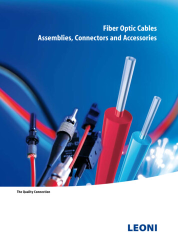
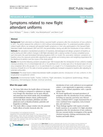
Radiation Effects Mercury Laser AltimeterLow Dose Rate Rad-Induced Attenuation for 200 (red) & 300 (blue) Flexlite Cable1.4Radiation Induced Attenuation (dB)1.21.024 dB10.917 dB200 micron0.8300 micron0.60.40.2000.511.52Total Dose (rads)2.533.5x 104Flexlite Radiation Test, 11.2 rads/min at –24.1 CRadiation Conclusion: .07 dB, using 11.2 rads/min, -24.1 C, 26.1 in, “dark”Results for 10 m, at 30 Krads, -20 C, 850 nm, 23 rads/min 1 dB or 0.10 dB/m
MSL Radiation Requirements using the LRO Radiation Model @ 532 nm,for the Polymicro FV400/440 (.22 NA)DurationDose RateRads/minTotal DoseTemperatureAttenuation36 months0.006410 Krad-80 C0.0015 dB/m36 months0.012620 Krad-80 C0.0030 dB/m8 months0.028910 Krad-80 C0.0025 dB/m8 months0.057820 Krad-80 C0.0049 dB/m Good extrapolation models will serve in analysis for other environments andmissions, saving time and in the end. There is a lot to lot variability so radiation testing should still be conducted. Radiation testing also serves as a screening for the COTS product. Defectiveproducts will show poor radiation performance.SPIE 6713
A Decade of Service from the Photonics Group forOptical Fiber Components and AssembliesCode 562, Electrical Engineering Division of AETD, NASA tionPerformance overHarsh EnvironmentGLASXXGSE2000-2008ISSISS-2003XFiber Optic Data BusXXMessenger - MLAXXSandia National Labs (DOE)ISS-Express Logistics CareerFailureAnalysisXXXXXAir Force Research LabXXXXXShuttle Return To FlightXLunar Orbiter Laser AltimeterXXXXXMars Science Lab ChemCamXXXXXLaser Ranging, LROXXXXFiber Laser IIP/IRADXXXESA/NASA SpaceFibreXXXUpcoming is the 3rd Event in coordination with ESA/CNES/JAXA/NASA on optics for space
What’s Coming? Diamond AVIM international standard for space. Multi Fiber Arrays– Linear, Bundled, Custom Patterns High Power Terminations– Fiber Lasers – Intersatellite Communications Ruggedized Fiber Optic Cables– Wide thermal range, rugged cable– For future missions or replacement on exising systems
ConclusionAll components are not appropriate for all applications.Knowledge of failure modes and materials is crucial to makingfeasibility decisions as well as design, manufacturing proceduresand test plans.
AcknowledgementsNASA Electronic Parts and Packaging Program forfunding this talk.For more information, please see the tp://nepp.nasa.govNASA Goddard Space Flight Center
Extra Slides
International Space Station 2000Failure Analysis: Optical FiberCable 1999-2000Failure Analysis: Optical FiberTermini 2005-2006StrengthMembersCoatingJacketBufferGlass FiberHermetic SealBad CombinationFiber Optic Cable “Rocket Engine” DefectsHermetic coating holes,Polyimide coating holds waterFluorine generated during extrusion of bufferHollow tube constructionwater and fluorine interaction results in HF acidHF etches pits into fiber getting through holes in coatingEtch pits deep into the core caused losses and cracks
International Space Station Study on Termini 2006Vendor provided termini that somehow passed integration QADuring integration by the contractor. Node 2 welded into place.Cost of changing termini on Node 2 more than 1 M. Node 3 fixed.32 termini areinstalled into one“MIL-C-38999”type connector.Termini end faces were found to be cracked after failinginsertion loss testing during integration.
ISS Termini Failure AnalysisThe below cross section of theterminus shows a concave end-face.This is per specification. If the endface were convex, the glass wouldlikely experience an impact whenconnected, causing a fracture.1mmThe fiber must be free of cracks inorder to prevent a degraded orblocked optical signal. If a glassfiber has a crack after the polishingprocess, the crack will grow overtime.The termination is made up of:A zirconia ferrulePolyimide coatingPure silica claddingGermanium doped coreSide View of Cross-sectionedFiber in the FerruleFerrule & Fiber End ViewThe end-face of this optical fiber is140µm. If dirt is present, the opticalsignal would be degraded or blocked.Core, Cladding, & Coating End View
ISS FA Optical MicroscopyFiber Most Likely to Fail Because of CrackOptical Microscopy:Bright Field Image at 200XCrack FormationDark Field Image at 200X Bright field (Top) & dark field (Bottom)illumination (taken at 200X) can be used to enhancecertain features of the terminus. At 200X, a crack formation can be seen, and the“smudge” appears to be sub-surface cracking. More information is required to characterize thecrack. Optical microscopy is not enough to identify anorigin of the crack, so SEM will need to beperformed.
ISS FA Scanning Electron MicroscopyFiber Most Likely to Fail Because of CrackScanning Electron Microscopy (SEM):BCrack FormationAA SEM gives a clear image of the crack, and could beobserved at over 50000X magnification. At 500X, the ends of the crack can be observed andanalyzed. A concave or convex profile of the end-face cannotbe determined using the SEM, so the terminus mustbe evaluated using confocal microscopy.B
Laser Ranging Fiber-Optic Bundle Optical Test Procedure LOLA-PROC-0107 Insertion Loss Measurement Procedure for The Laser Ranging Optical Fiber Array Bundle Assemblies LOLA-PROC-0111 Mating of Two LR 7-Fiber Optical Fibers Using Cleanable Adapter LOLA-PROC-0142 Cutting Back The Kynar Strain Relief For Integration LOLA-PROC-0143