Transcription
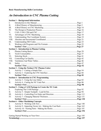
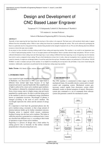
International Journal of Scientific & Engineering Research Volume 11, Issue 6, June-2020ISSN 2229-5518Design and Development ofCNC Based Laser Engraver1Jayaprasad V C,1G Sahajananda,1Lohith K S,1Harishankara P,2Karthik.S1UG students & Assistant ProfessorSchool of Mechanical Engineering.REVA University, BengaluruABSTRACTBasically in laser engraving the laser beam burns the top layer of the surface to be engraved. The burnt area is left uncolored which makes it appeardifferent from the surrounding surface. While in laser cutting laser beam has to penetrate through the surface. This can be achieved by prolonging thebeam on a particular area for a long period of time, duration being decided on the strength of material to be cut. We are still collecting data from differentresources to know this topic more in depth.In our project we have decided to develop working model of laser cutting and engraving machine. This machine is very useful in our department sinceit’s a kind of rapid prototyping machine. It can cut out paper patterns and thermoplastic sheets to produce desired shape and patterns. Till now we havecollected information on laser cutting, laser and what engraving is. Laser cutting is different from laser engraving, in case of engraving very low intensitylaser torch is used as compared to laser cutting. We got a brief introduction on laser, how it works, what are its properties, how to generate it and how tocontrol its intensity. It might nut cut through chunks of wood but surely burn the top layer. Simulation analyses are performed in CAD software ‘SOLIDIJSERWORKS’ in order to simulate each part of the machine. It was helpful for remodeling the moving bed or the job holder, if any errors found during thesimulation. Additionally, experiments are performed for the develop laser cutting engraving machine.Index Terms- CNC Shield, G-code, Arduino, Stepper motor, SMPS1. INTRODUCTIONLaser stands for Light Amplification by Stimulated Emissionof Radiation, was discovered in 1960. Laser light beam isdifferent from normal light beam because of its hightemporal and narrow spectral bandwidth. Here amplificationof light is achieved by a laser active medium (gain medium).This medium is obtained by stimulated emission of photonsfrom a lower energy state to a higher energy state previouslypopulated by a pump source. In order to start the lasing activein the medium it must be in nonthermal energy distributionknown as population inversion. Wavelength of photon ischanged according to the need of active medium. Thewavelength represents the colour and the amount of energystored.It is important to feed back the generated photon into theactive medium using a resonator, so that a large amount ofidentical photons builds up for further stimulated emission.Pumping action is required which ensures continuousfeeding of energy into the laser active medium. This helps insufficient emission is generated on a continuous basis. Lasersare classified into different ways i.e. according to their modeof operation or type of laser-active medium.Engraving is a process of design onto a hard surface bycutting grooves into it, basically on flat surface orientedperpendicular to the processing beam axis.2. METHODOLOGYThe CNC machine is constructed in three stages: (a) buildmechanical frame, (b) assemble electric system and (c) installcontrol and computing system. Mechanical system getsnecessary control signals from electronics system whichultimately results in desired actuation of motors. Electronicssystem gets command or a set of commands from softwaresystem and generates controls for mechanical system.IJSER 2020http://www.ijser.org155
International Journal of Scientific & Engineering Research Volume 11, Issue 6, June-2020ISSN 2229-55181563. DesignThe CAD software which has been used for designingand virtual analysis of the model is “solid works 16”which is a very versatile and flexible CAD software. Byusing solid works the conceptual idea of the design isconverted in to virtual detail design, the below figuresi.e. fig 1 shows the isometric view of the shreddermachine.(a)Acrylic(b)Time Pully(c)WheelThe Astro Industrial Duty Aluminum 2020H EuropeanStandard Anodized Profiles made of High Grade temperedAluminum Alloy 6063 - T5. The dimensions are as perEuropean Standard and the structural cross section thicknessis minimum of 1.5 mm. The profile can be used for structuralelements in automation machinery, laser cutting machines or3d printers. Also many prototype CNC router machines, XYtables or camera sliders can be made using the same. Theprofile is anodized in natural aluminum color to provide a hardlayer to prevent corrosion and wear. We have a number ofaccessories available to easily assemble various structuresusing the 2020 profile. Please check out the same in theAluminum Profile Accessories Section.IJSERFig 1: Isometric view4.Mechanical SystemFig 2: 20x20 Aluminum ProfileThe mechanical system is assembled in such a way that the 3axis movement is achieved by using the linear bearings andguide rods. Stepper motors are mounted to the each axiswhich is the source of motion acted according to the controlsignal generated from the electronics circuit. Each stepper motor is coupled to the screw rod which carries nut with the helpof coupling bush. This screw rod and nut arrangement is responsible for converting the rotational motion of the steppermotor to linear motion. The linear motion of each axis is carried away smoothly by the linear bearing and guide rod assembly connected to the each axis which is capable of loadcarriers and allows linear motion in each axis. The controlledmotion in each axis is achieved directly by controlling therota- tion of the stepper motor. The speed of the motion in eachaxis can also be controlled by direct control of the speed of thestepper motor by giving required control signals. Thus the toolpath of the spindle fixed to the end effector is controlled ineach axis for smooth carving or cutting action of work piece.5. Electrical SystemArduino uno is selected to be the control unit in this project.The arduino uno is a microcontroller board based on theATmega328 chip. The microcontroller board is flashed withG- code interpreter code which was written in the C language.The control board is responsible to generate the control signalfor corresponding command signal from the computer to thestepper motors which is directly controls the motion of the toolpath. Fig. 4. displays the functionally of the Arduino pins asused by GRBL. The driver called easydriver (Fig.6) is used asthe stepper motor driver. It receives steps signal from microcontroller and convert it into voltage electrical signals thatrun the motor.Fig 3: Arduino UnoIJSER 2020http://www.ijser.org
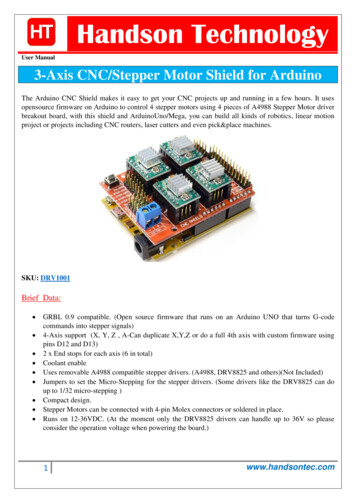
International Journal of Scientific & Engineering Research Volume 11, Issue 6, June-2020ISSN 2229-5518Connection Diagram:5.1 CNC ShieldThe Arduino CNC Shield makes it easy to get your CNC projectsup and running in a few hours. It uses opensource firmware onArduino to control 4 stepper motors using 4 pieces of A4988Stepper Motor driver breakout board, with this shield andArduinoUno/Mega, you can build all kinds of robotics, linearmotion project or projects including CNC routers, laser cuttersand even pick&place machines.Fig 4: CNC shieldHooking Up the Stepper Motor to CNC ShieldConnect steppers motor to CNC Shield board as the belowblock diagram. of the CNC Shield connected to 3-steppermotor:IJSERFig 5: Line Diagram of Connection between AurdinoMicrocontroller and Stepper MotorFig 7: A4988 can also be interfaced with Arduinothrough CNC Sheild:5.2Stepper Motor Driver (A4988):The A4988 is a complete micro stepping motor driver withbuilt-in translator for easy operation. It is designed to operatebipolar stepper motors in full-, half-, quarter-, eighth-, andsixteenth-step modes, with an output drive capacity of up to35 V and 2 A. The A4988 includes a fixed off-time currentregulator which has the ability to operate in Slow or Mixeddecay modes.6.GRBLSoftware:GRBL is opensource software that runs on Arduino Uno thattaks G-code commands via Serial and truns the commandsinto motor signals. GRBL source code is added to Arduinolibrary and Arduino IDE is used to flash GRBL directly to theArduino board.Grbl Controller is software that is designed to send G-code toCNC machines, such as 3D milling machies. It just needs togive the user a nice way to get command down to whatevercontroller they are using. Grbl Contoller is written using the Qtcrossplatform libraries. It also gets some help from theQextSerialPort library to simplify choosing the correct USBserial port.Fig 6: Stepper Motor Driver (A4988)IJSER 2020http://www.ijser.org157
International Journal of Scientific & Engineering Research Volume 11, Issue 6, June-2020ISSN 2229-5518158fig 8: GRBL ControllerFig .9: Laser Engraver Modle7.Objective of the WorkThe objectives of the work are:9. Project Schedule:a) To reduce the large scale industrial cutting machine to asmall portable lab equipment.Laser Engraver development cycle include three major phases.Very first stage is mechanical design using Solid works.3Modelling of each part has been done which include X, Y &Z-axis and final assembly will be done in Solid works softwareand converting into 2D and BOM generation. After this we aregoing for the manufacturing of the different parts using 3Dprinting.b) To decrease the cost of making prototypesc) To make it useable for cutting paper, polystyrene and thinsheetsIJSERd) Make the machine mobile.e) Developing concept sketches and then reviewing it with thecustomers to find according to them what the shapes shouldbe.8.Machine SpecificationThe technical parameters of the machine are shown in table1 and the complete assembly of the CNC machine isillustrated in Fig9.TABLE 1TECHNICAL PARAMETERSMachine dimension600 460 180 (mm)(L*W*H)Working area300 380 (mm)Z-axis travel100mmDriver motor3 Stepper motorLaser Power2.5w/2500mwLaser Wavelength445nmControllerPC based GRBL ControllerEngraving Accuracy0.01mmSecond phase includes understanding the working area of theLaser engraver machine and Kinematics of the Cartesian coordinate systems is analyzed. In this phase, we are also goingfor type of microcontroller is used and different electroniccomponents & their interface with Microcontroller andprogramming. We are going do the wiring of all electroniccomponents has been done.Third and final phase is understanding G-codes and M-codes &Interfacing software to do the Job by using G-Codes and Mcodes.Result: Design of the Laser Engraver in which we do Engravingon Plywood, plastic, paperIt should works by uploading G-codes & M-CodeFuture Plan of Action for Phase 2: 3D design of X, Y & Z axes in Solid works.3D Printing & modelingLaser Module selectionElectronics selection & wiringMicrocontroller ProgrammingIJSER 2020http://www.ijser.org
International Journal of Scientific & Engineering Research Volume 11, Issue 6, June-2020ISSN 2229-5518P.Jamaleswara Kumar, M.Gowtham “ Design and fabrication ofportable laser cutting and engraving machine ” InternationalBy using CNC controllers, there is a remarkable increase Journal of Engineering & Technology, 7 (1.1) (2018) 570-573.in the quality of products as well as it offers highflexibility. It increases the productivity and reduces thelead time. This collaboration of hardware with G-code &M-code gives better productivity and reduces the workload.G-code & M-code make easy to find the informationof locations of all stepper moter moving, as the status ofour moving moter are directly seen on computer. Makinga small machine brings a flexibility to do work and alsodecrease the cost of making prototypes, make it useablefor cutting paper, polystyrene and thin sheets.In this work, designed and fabricated with alow-price. Inconclusion the accuracy of the designed and fabrication ofCNC based laser engraver body parts assembling hassucceded to achieve the objectives of this project inprecisionly and repeatability goal.10.Conclusion:Advantage : Low weightEasily transportableLow costEasy setupIJSER10.ACKNOWLEDGEMENTThe authors wish to thank Dr. Khaing Thida and Dr. Swe ZinNyunt for their guidance. This work was supported in part by agrant from Department of Mechanical Engineering, ThanlyinTechnological University.11. ReferencesC. Leone, “wood engraving by Q-switched diodepumped frequency-doubled Nd: YAG green laser ”Optics and lasers in engineering 47(2009) 161-168.Yusri Yusof, “New Interpretation Module for OpenArchitecture Control based CNC Systems ” 12 th globalconference on sustainable manufacturing, Pocedia CIRP 26(2015) 729-734.”Georgi M. Martinova, Aleksandra I. Obuhova, Lilija I.Martinovaa, Anton S. Grigorieva. “An approach to buildingspecialized CNC system for non-traditional processes”.Procedia CIRP 14 (2014) 511-516.Yu D, Hu Y, Xu XW, Huang Y, Du S. “An open CNC systembased on component technology”. IEEE Trans Autom Sci Eng2009;6.Correa J, Toombs N, Ferreria PM. “Implementation of an openarchitecture control for CNC system based on open-sourceelectronics”. Proceedings of the ASME 2016 IMECE 2016.IJSER 2020http://www.ijser.org159
8.Machine Specification. The technical parameters of the machine are shown in table 1 and the complete assembly of the CNC machine is illustrated in Fig9. TABLE 1 . TECHNICAL PARAMETERS . Machine dimension 600 460 180 (mm)(L*W*H) Working area 300 380 (mm) Z-axis travel 1