Transcription
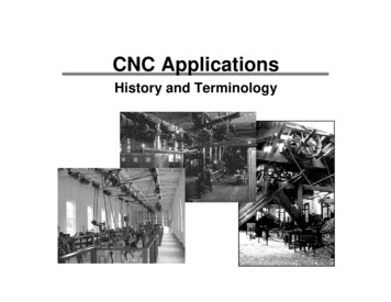
CNC MACHINES
Machine Control SystemsMachine controls are divided into four groups:(a) Conventional Machine System (Manual Control)(b) Traditional Numerical Control (NC)(c) Computer Numerical Control (CNC)(d) Distributed Numerical Control (DNC)
Overview of a Basic -axisTailstock assembly
(b) NC Machines Numerical control(NC) refers to the method of controlling the manufacturing operations bymeans of directly inserted coded numerical instructions into the machine tool. Numerical Control is defined as a form of software controlled automation, in which the process iscontrolled by alphanumeric characters & symbols ( i.e. number , letters, and symbols.) According to these definitions, a programme is prepared which consists of combination ofcharacters and numbers in sequence describing the position of the tool and job, the cuttingspeed and feed. The first NC machine was built in the 1940s and 1950s, based on existing tools that were modifiedwith motors . The part program is entered on the program tape/Magnetic tape in the form of punched holes. Then the tape is inserted to the Tape Reader which is the the Machine Control Unit. An NC machine is numerically controlled but has no memory storage and is run off of the“tape” each time the machine cycles.
Punched tape for NC Machine Punched tape or perforated paper tape is a form of data storage, consisting of a long strip ofpaper in which holes are punched to store dataFig. Punched TapeFig. Paper tape reader
(c) CNC Machines CNC refers to a system that has a local computer to store all required numerical data. The advantages of CNC systems are to store and execute a number of large programs, toallow editing of programs, to execute cycles of machining commands, etc.(d) Distributed Numerical Control (DNC) Distributed Numerical Control (DNC) is similar to CNC, except a remote computer is used tocontrol a number of machines. An off-site mainframe host computer holds programs for all parts to be produced in theDNC facility. Programs are downloaded from the Mainframe Computer, and then the local controllerfeeds instructions to the hardwired NC machines. The recent developments use a central computer which communicates with local CNCcomputers (also called Direct Numerical Control).
Basic Progression to a CNC M/c
Types of CNC Machines CNC Turning Centre CNC Milling Machine CNC Horizontal Machining Centre (HMC) CNC Grinder CNC Drilling Machine CNC Gear Cutting Machine CNC Turret Punch Press
Figure 1.3 : Coordinate System (Turning Operations)
Figure 1.2 : Coordinate System (Milling and Drilling Operations)
CNC MACHINING CENTRE:1. Vertical Machining Centre (VMC): Vertical spindle configuration comprising of three basic servo axes(X - axis, Y-axis & Z - axis ): Two for the table movement and one forthe spindle head.
2. Horizontal Machining Centre (HMC): It can perform machining on different faces of a cubical or prismatic component. Both VMC and HMC uses Auto Tool Changer (ATC ) & Automatic Pallet Changer(APC)
Auto Tool Changer (ATC ) & Automatic Pallet Changer (APC) ATC ( Auto Tool Changer ) is a device which can automatically change thetool from the tool magazine to the machine spindle as per the CNCprogramme. Tool Magazine is a device which holds number of tools and canautomatically index to enable ATC to pick the right tool and to replace theused tool. Automatic Pallet Changer (APC) is a device which can automatically changethe pallet to/from machine to pallet stand. By this Mechanism ( i .e. APC ) the pallet with the finished component andthe pallet with a raw component could be exchanged automatically.
ATC & Tool Magazine
Automatic Pallet Changer (APC)Pallet is a transferable work tablehaving T’ slots or tapped holes forcomponent/fixture clamping.Used to avoid the machine waitingtime during loading & unloading ofcomponent.Pallet is held on the machine table bylocating pins and clampingmechanism to ensure repeatabilityand accuracy.
Contents of mechanical and electronic software and hardware indifferent manufacturing facilities
CNC SYSTEMS Computer Numerical Control (CNC) is computer based system to store andprocess data for control of slide motions and auxiliary motions of machine tools. CNC Systems are constructed with NC Unit integrated with HMI,Programmable Logic Controller (PLC) with a ‘Feed Back Device’. PLC controls the ON/OFF functions of the machine tool. It sets the output basedon the input conditions & corresponding logic.PLC Functions: Coolant ON/OFF. Spindle ON/OFF. Selection of a tool. Change of workpiece (Pallet Changing). Workpiece clamping etc.
Components of a CNC Machine» CNC System (Controller)» Drives.» Servo Motors» Actuators» Sensors/ Feedback devices.
HOW A CNC SYSTEM WORKS ?CNC SYSTEMDISPLAYUNITPERIPHERALINTERFACE(MMI OR HMI)DRIVES & ELECTRICALSSYSTEMKEYBOARDAXES ORSERVOCONTROLLERCOMMANDSAXESDRIVESPOS. F/BsFROM M/CTOOLDRIVE MOTORSAXES MOTORSWITHPOSITION& ROLLERI/OCONTROLLER(PLC)F/B FROMM/C DLE MOTORWITH POSITION& SENSORS /FEEDBACK DEVICEMACHINETOOL
CLASSIC SERVO LOOPPOSITION LOOPD/A Converterchanges followingAccumulator holds error to analogfollowing errorvoltageVELOCITY LOOPSlideServo MotorAmplifierInterpolator issuesposition commandsPosition feedback issubtracted fromposition commandto providefollowing errorSpeed feedback issubtracted fromspeed commandTachoPosition TransducerMonitors Position
Analog Servo Loop in CNC SystemFollowingerror signalAccumulatedCommand -Velocity Error VelocitySignalAmplifierDAC SlideCurrentAmplifier-MLead orVELOCITY FEEDBACKPOSITION FEEDBACKCNC SYSTEMDRIVES
Special Features of CNC M/c Mechanical Features:» Ball Lead Screws.» Linear Bearings.» Improved Guide ways.» Timing Belts.» Curvic Coupling.
Smooth Linear Motion. Low starting friction. Wear resistant. Very Low Backlash.Ball Lead Screws
Linear Bearings on guide-ways Smooth Linear Motion. Low starting friction. Wear resistant.
Toothed Belt, Steel-wires.Slip-Proof Drive.Timing Belt
Used in Turret Indexing of CNC m/c.Curvic Coupling
Fanuc Series 0i SystemCNC ControllerDrive amplifierServo motorFanuc Serial Servobus (FSSB) Spindle Interface (Serial)SpindlemotorFanuc I/o LinkConnection PanelI/O ModulesMOPI/O devices
System Features» Centralized Lubrication System.» Operating features» Programming features» Communication features» Compensation features» Safety and diagnostic features
Centralised Lubrication System
Online Machine Diagnosis System
Operating FeaturesBasic Operating Modes: JOG Mode MDI MODE AUTO MODE
JOG MODEManual movement of axes.Manually select the tool.Manually move the axes.Find the tool offset.MDI MODEProgram phase.Manually feed the program.AUTO MODECreate a Program.Store the ProgramExecute the program
Programming Features Inch / Metric Programming Absolute / Incremental Programming Linear / Circular / Helical / SpiralInterpolation Full Circle Programming Subroutine Programming
Communication Features Upload / Download Of ProgramsMachine Status Monitoring
Compensation Features Tool Offset & Work offset Tool Length Compensation Diameter Compensation
WORK OFFSET
TOOL OFFSET
TOOL OFFSET
Safety And Diagnostic Features Emergency Stop Axis Overtravel Power Up Diagnostics
CNC NUC INDIAFANUCSPAINSPAINJAPANINDIAJAPANFAGOR 800, 8025, 8050FAGOR 800, 8025, 8050FANUC 15i/150i, 16i/160i, 18i/180i, 21i/210iFANUC21i/210i,0 , 0iFANUC NYTNC 155, 426, 430NUMFRANCENUM 1040, 1050, 1060SIEMENSGERMANYSINUMERIK 810, 820, 840, 880FANUC INDIAHEIDENHAINMITSUBISHIELECTRIC AUTOMATION INC.INDIAGERMANYJAPANFANUC 0 , 0iTNC155,426, TPLUS430 AND 600M64 CNC, FUSION640,MPLUS,SERIES.GSK CNC EQUIPMENTCHINAGSK980TDa., GSK983MSIEMENSGERMANYSINUMERIK 802, 840, 880MITSUBISHI ELECTRIC AUTOMATION INC.JAPAN70/700 SERIES, C6/C64 SERIES, 60S/E60/E68SERIES
CNC PROGRAMMINGBasic steps in CNC machining:i) First, prepare the program from part drawing .(ii) The part program is then read to the CNC system.(iii) Then the workpiece & tool are mounted on the machine.(iv) Then the tool is operated according to the programming( Execute the program).
Program configuration
Block configuration
G - CODESG-codes are used to move the tool or axes by Program.G 00 – Rapid travel.G 01 – Linear interpolation.G 02 – Circular interpolation clock-wise.G 03 - Circular interpolation anti-clockwise.G 04 – Dwell time.G 20 – Inch data inputG 21 – Metric data input.G 22 – Stored stroke check on.G 23 - Stored stroke check off.G 27 – Reference point return check.
.G 28 – Reference position return.G 29 – Return from reference pointG 30 – Return to second reference point.G 31 – Skip function.G 32 – Thread function.G 36 – Automatic tool compensation XG 37 - Automatic tool compensation ZG 40 – Tool nose radius compensation cancelG 90 – Absolute dimensioning.G 91 – Incremental dimensioning.G 98 – Feed rate in mm/min.G 99 - Feed rate in mm/rev.
M- CODES ( Miscellaneous Codes ) ON/OFF Codes. Controlled by PLC.M 00 – Optional stop.M 01 – Programmable stop.M 02 – Main program end.M 03 – Spindle clock-wise.M 04 – Spindle counter clock-wise.M 05 – Spindle stop.M 06 – Tool change.
M 07 – Coolant b on.M 08 - Coolant a on.M 10 – Chuck open.M 11 – Chuck close.M 13 – Spindle forward & coolant on.M 14 - Spindle reverse & coolant on.M 16 – Special tool call.M 17 – Sub-program end.M 19 – Spindle orientation.M 30 – Main program end & rewind.
7. Araw material of size: ǿ 40 and60 mm. length is supplied to you .Make a CNC part program for stepturning of the given job as shownin the diagram.ǿ 382010ǿ 36
Step Turning: O 0001;N10 G21 G99 ; N20 G28 U0.0 W0.0; N30 T01 D01 M06 ; N40 S1000 M03 ; N50 G00 X41.0 ; N60 G00 Z0.0 ; N70 G01 X0.0 F1.0 ;
N80 G00 Z5.0 ;N90 G00 X41.0 ;N100 G00 Z0.0 ;N110 G01 X38.0 F1.0 ;N120 G01 Z-30.0 ;G130 G01 X41.0 F1.0 ;G140 G00 Z0.0 ;G150 G01 X36.0 F1.0 ;N160 G01 Z-10.0 F1.0 ;N170 G01 X41.0 F1.0 ;N180 G00 Z0.0 ;N190 G28 U0 W0 ;N200 M05 ;N219 M30 .
THANK YOU
CNC SYSTEMS Computer Numerical Control (CNC) is computer based system to store and process data for control of slide motions and auxiliary motions of machine tools. CNC Systems are constructed with NC Unit integrated with HMI, Programmable Logic Controller (PLC) with a ‘Feed Back Device’. PLC controls t