Transcription
GSK928MAMilling Machine CNC SystemUser ManualGSK CNC Equipment
The operating manual describes all matters concerning the operation of the system in detail asmuch as possible. However, it is impractical to give particular descriptions of all unnecessaryand/or unavailable works on the system due to the text size limit of the manual, specific operationsof the product and other causes. Therefore, the matters not specified herein may be consideredimpractical or unavailable.This operating manual is the property of GSK CNC Equipment Co., Ltd. All rights reserved. It isagainst the law for any organization or individual to publish or reprint this manual without theexpress written permission of GSK and the latter reserves the right to ascertain their legalliability.Dear user,We are really grateful for your patronage and purchase of GSK928M milling CNC system made byGSK CNC Equipment Co., Ltd.Company ProfileAs an industrial base of numerical control (NC) products in south China and an enterprise undertaking thestate’s Plan 863 “Middle-grade Numerical Control System Industrialization Supporting Technology”, GSKhas been committed to the development and manufacture of NC systems for machine tools andservo/step motor drive units for years. GSK actively promotes machine tool NC innovation and offers NCtechnical training and trade services of numerical controlled machine tools – integrating science,engineering and trading. Our products support more than 50 domestic manufacturers of machine toolswith after-sales service network through the country. With a yield in the lead in China for four years insuccession, GSK series products are in great demand in the domestic demand and have sold as far as toSoutheast Asia at high cost-performance ratio.Field Technical Support ServiceField support services are available when you encounter problems insolvable through telephone. GSKCNC Equipment Company Limited will designate a technical support engineer to the field to solvetechnical problems for you.All specification and designs are subject to change without notice。Sincerely thanks for your friendly support for our products.
ContentsProgramming1 Introduction. 51.1Axis Definition . 51.2Machine zero. 51.3Reference point . 51.4Coordinate System . 51.5Programming Coordinates . 61.6Input Unit and Range of Coordinate . 61.7Program Configuration. 61.8Tool Path of Rapid Positioning . 81.9Offset of System Coordinate . 81.10Initial and Modal of System. 81.11Initial Status of System. 81.12Start of Program . 91.13End of Program . 91.14Main Program and Subprogram. 91.15Backlash Compensation .101.16R Reference Plane.102 S, T, M Function, D, H, F, FEED%.112.1S Function .112. 2T Function .112.3M Function (Auxiliary Function).112.4D, H Function .132.5F, Feed%.133 G Function (Preparatory Function).143.1G Function for Defining Programming State of the System .143. 2G0 Rapid Positioning (Modal, Initial) .143. 3G1 Linear Interpolation (Modal).153.4G2, G3 Circular Interpolation (Modal).153. 5G4 Dwell.163. 6G10 G11 Rough Milling in Concave Groove of Inner Circular .163. 7G12 /G13 Finish Milling of Inner Circle.173. 8G14 /G15 Fine Milling of Outer Circle .183. 9G22 System Parameter Setting (Modal) .183.10G23 Conditional Jump.193.11G27 Machine Zero Inspection.193.12G28 Rapid Traverse to Reference Point via Middle Point.203.13G31 Rapid Return to the R Reference Plane .203.14G34/ G35 Rough Milling of the Rectangle–concave Groove.202
3.15G36/ G37 Fine Milling Within the Rectangle-concave Groove .213.16G38/ G39 Finish Milling Outside of the Rectangle .223.17Summary to G Function of Fixed Cycle .223.18G73 High Speed Drilling Cycle .243.19G74 Tapping Cycle with Left-hand.243.20G81 Drilling Cycle.253.21G82 Drilling Cycle.253.22G83 Deep Hole Drilling (Perking)Cycle .263.23G84 Right-hand Tapping cycle.263.24G85 Boring Cycle .273.25G86 Boring Cycle (drilling along head) .273.26G89 Boring Cycle .283.27G92 Floating Coordinate System Setting .284 Parameter Programming.29Operation5 Introduction.315.1Control Panel and Function buttons .315.2Adjusting of LCD Brightness.325.3Indicators and Function Keys .325.4Operation Mode and Incremental Input.355.5Resetting Power On .355.6Operation of Menu.355.7Main Menu for the System .366 Parameter Setting.376.1Description of Parameter .377 Manual Mode.437.1Manual Operation.437.2Display (Disp).457.3Zero Return Function (ZERO) .467.4Command Function (COMM).478 Auto Mode .498.1Auto Operation .498.2Display Function (Disp) .518.3Command Function (Comm) .518.4Run to Current Block in Dry Run and Positioning Run .538.5Escape from Auto Mode (end).548.6Executing a Part Program.548.7Execution Order in Auto Mode.558.8Run Times of Part Program .558.9DNC Operation.568.10Power Down Protection.563
9 Dry Run Mode .5710 Edit Mode.5810.1Full Screen Edit (1-EDIT) .5810.2List of Program (2-LIST) .6010.3Program Copy (3-COPY) .6110.4Part Program Memory Area Lock (4-LOCK) .6110.5Part Program Memory Area Unlock (5-UNLOCK).6110.6Deleting a Program (6-DEL) .6210.7Initialization of Part Program Memory Area (7-P INIT) .6211 Communication Mode .6312 Notes and Procedure of Operation.66Connection13 Interface Overview .6713.1Interface Layout.6713.2Total Frame .6713.3 Total Connection Graph.6814 Interface function .6814.1Interface Specification.6814.2Interface Pin list and Interface Method.6815 Interface connection .7115.1 Connecting with PC.7115.2 Connecting GSK928MA CNC System and Feed Drive Device .7115.3Connecting GSK928MA CNC system and Toolpost .7715.4Connecting GSK928MA CNC System and Manual Pulse Generator(MPG) .7815.5Connecting with spindle Encoder.7915.6CNC system Switching Value Input.7915.7Switching Value Output of the CNC System .81Appendix A:Introduction for GSK928MA .83Appendix B:System Parameter List.85Appendix C:M Function Word List.87Appendix D:G Function Word List .89Appendix E:Error Word List and Troubleshooting.91GSK928MA Machine Zero Return Mode .94GSK928MA Interface Circuit Diagram 1.95GSK928MA Interface Circuit Diagram 2.96GSK928MA Integrated System External Circuit Diagram.97GSK928MA Toolpost Controller Circuit Diagram .98GSK928MA Contour Installation Dimension Diagram .99GSK928MA-L Contour Installation Dimension Diagram.1004
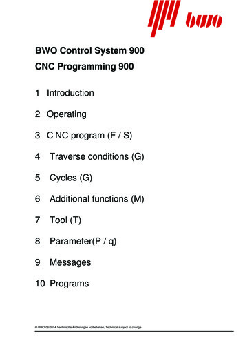
GSK928MA CNC SYSTEM OPERATION MANUALProgramming11.1IntroductionAxis DefinitionThis is the CNC system with three or four coordinates for the milling machine and drill machine etc.A rectangular coordinate system combined of X axis, Z axis, Y axis and C(or A)axis is used toexecute the positioning and interpolation operation in this CNC system. X axis is denoted to leftand right direction and Y axis to clockwise and counterclockwise direction for milling machine in thehorizontal plane, Z axis is denoted to vertical one for worktable(or milling cutter)and C (A) axis isan additional one(the 4th axis).Whether A or C is used as the 4th axis in programming axis is confirmed by the C bit of No.10system parameter No.10. A positive direction is defined to the tool moving away from the workpiece;otherwise it is negative direction as follows:YZ刀具X工件机床1.2Machine zeroMachine zero is a fixed point close to the proximity switch on a machine tool. Usually the referencepoint is set at the maximum stroke of X, Y, Z axis in the positive direction. Do not use its function,supported by the system without installing the machine zero. There must be a machine zerodeceleration switch before machine zero. It is unavailable for the 4th axis to use the machine zerofunction1.3Reference pointThe position used for executing part programs is defined to reference point), namely, the startingpoint of tool or the origin point of machining [instead of (0, 0) of coordinate system].1.4Coordinate SystemIn this system, a program is programmed based on the workpiece coordinate system (that’s to saythe workpiece coordinate system is equal to the programming coordinate system), it is suggestedthat the user should position the X , Y, Z axis’s zero with G0 instruction at the first block in theprogram. It can also define a floating coordinate system by instruction G92 in the program, and for5
GSK928MA CNC SYSTEM OPERATION MANUALthe convenience of programming, G92 can be used repeatedly in the program. The system willremember the position of machine zero and reference point. After executing the instruction G27(return to the machine zero and test the step out), G28 (return to the reference point through thespecified point), M02, M30, M31, the system will be changed from the floating coordinate system tothe workpiece coordinate system.Parameter from No.61 to No.84 is the position of G54 toG59 coordinate system in the referenceworkpiece coordinate system, which can be modified to change the position of No.1 to No.6workpiece coordinate system in the reference workpiece coordinate system. And the coordinate ofcurrent coordinate system can also be set in Manual mode.If the current coordinate system is not the reference workpiece coordinate system, thecorresponding code of current coordinate system will be displayed at the bottom of the screen inthe Manual or Auto mode: G92/G54/ /G59.In “Manual mode”, the current coordinate system can be switched “instruction” operation, and theworkpiece coordinate system can also be selected by G54 G59 instruction in program. Afterexecution of G27/G28/M02/M30 instruction or machine zero return, the system will be switched toreference workpiece coordinate system.When the workpiece coordinate system is selected by G54 G59 instruction in part program, theinstructions can be in the same program block with interpolation and rapid positioning G instruction ,and it will be executed firstly.1.5Programming CoordinatesWe can program with absolute coordinates (G90) and relative (incremental) coordinates (G91),incremental coordinates are contrast to the current position’s coordinate.1.6Input Unit and Range of CoordinateRectangle coordinate is used in the system.The least input unit of the coordinate value is 0.01mm. The maximum instruction value is 99999.99.Axis name1.7Least output unitX axisLeast input unit0.01mmZ axis0.01mm0.01mmY axis0.01mm0.01mmA(C) axis0.01mmActual move depending on the design of machine0.01mmProgram ConfigurationThe part program consists of a number of program blocks. Each block specifies the S function ofthe spindle speed, tool function (H for tool length compensation, D for tool corner radiuscompensation), miscellaneous function (M function) and preparation function (G function) for rapidpositioning and cutting feed. And each block consists of a number of words; the word begins withan English character followed by a value. The block begins with word N (block number), followedby other words, and ends with Enter key.Each block must consist of a sequence number for indicating the CNC operation sequence at the6
GSK928MA CNC SYSTEM OPERATION MANUALbeginning of the block and a Enter code for indicating the end of the block. A Letter N followedby a numerical value specifies the sequence number.For example:N10 G0 X50 Y100 Z20 N20 G91 G0 X-30 Z-10 N30 G1 Z-50 F40 N40 G17 G2 X-10 Y-5 R10 N50 G0 Y60 Z60 N60 G28 X0 M2 Block No.10, rapid positioningBlock No.20, relative programming, rapid positioningBlock No.30, linear interpolation (linear cutting)Block No.40, circular interpolationBlock No.50, rapid positioningBlock No.60, return to starting point, program endingFor the above, N30,G1,Z-50,F40 etc. are called for words, the beginning character of word standsfor significance of word, and the following digits are the word value. For the expression of valuerange, here N4 represents that the word value range is 4-bit integer(0 9999). And the range forX 5.2 is from -99999.99 to 99999.99. (i.e. maximum 5 integral bit and maximum 2 decimal bit, and- sign is allowable)The configuration of one block of program in this system is designated as follows:/ N5 X 5.2 Y 5.2 Z 5.2 A 5.2 C 5.2 I 5.2 J 5.2 K 5.2 U5.2 V5.2 W5.2 P5 Q5.2 R 5.2 D1 H1 L5F5.2 S2 T1 M2/Optional block skip code. When a slash is specified at the beginning of a block, this blockis an optional block. When the optional block skip indicator on the operation panel islight, the information in the block with a slash heading will be ignored in Auto mode, andOne touch of the skip key can switch off the optional skip function.NBlock sequence number ranged from 0 to 65535; it is a default, and it must be the firstsign of the block if it contains N. (It can be omitted in DNC.)Preparatory function, several G instructions for defining states and one G instruction foractingcan be specified in the same blockX ,Y,Z,A,CCoordinate value ranging from –99999.99 to 99999.99 in each axis;Absolute(G90) or relative(G91) value;Whether A or C is available in programming to the forth axis is confirmed by the C bit ofNo.10 parameter.I,J,KThe position K of the center of circle, which is relative to the starting point in circularinterpolation.K is denoted to the spindle speed in tapping.PDwell time; Parameter number; Program number;RArc radius, the reference plane(R plane) in the fixed cycleDLThe number for tools(0 9);used for the tool radius compensation;HRepetition count ranges from 0 65535;The number of holes to be drilled;FThe number for length of tools(0 9);used for the tool length compensation;Cutting feedrate, the unit is mm/min or mm/r;SSpindle speed;TThe function of tool change;7
GSK928MA CNC SYSTEM OPERATION MANUALM Auxiliary function for the starting and stop of spindle ,water pump and the inputting andoutputting by user;Enter code, End of block code;Free format is used for program block. Except the requirement of the beginning with “/”, “N”, otherword (a letter following by a numerical value) may be put in any sequence. And the block ends withthe ENTER sign.1.8Tool Path of Rapid PositioningThe sequence of rapid positioning is as follows:It’s Z axis, X axis, Y axis, the 4th axis in turn when the direction of Z axis is positive.It’s X axis, Y axis, the 4th axis, Z axis in turn when the direction of Z axis is negative.It’s X axis, Y axis, the 4th axis in turn when there is no positioning in Z axis.1.9Offset of System CoordinateThe offset of the system coordinate (coordinate offset in X, Y, Z, C axis direction) can be set byparameter No. 55, 56, 57, and 58 respectively, which can be redound to adjust the machiningremainder conveniently, without modifying the program.1.10Initial and Modal of SystemInitial status is defined that t the programming status before the program runs. It is the defaultstatus of the system when power-on. The modal is defined that the corresponding word is validafter the instruction is specified until another block is specified. Another meaning for the modal: theword does not be input again in the following block for the same function after it is set.1.11Initial Status of SystemThe initial status of this system after power on is listed as follows:ItemStatusDescriptionProgramming modeG90Programming with the absolute coordinateG17Selecting X-Y plane for circular interpolationG40Canceling tool radius compensationG49Canceling tool length compensationUsing reference coordinate systemItemModal G codeStatusDescriptionG80Modal data in non-fixed cycleG94Speed state in feed per minuteG98Return starting point in fixed cycleG0Rapid positioning8
GSK928MA CNC SYSTEM OPERATION MANUALRapid traverse rateDepending on parameter No.1 (G0SPD)Cutting feedrateDepending on parameter No.2 (G1F)Current 12Current coordinate, the tool position after the latestAuto operation or Manual operation.Current statusStart of ProgramAt the beginning of program executing, the tool nose tool should be at the position in which the toolbe changed. It is suggested that G00 X Y Z should be programmed in the first block of theprogram to position the tool to the starting point in absolute coordinate; otherwise the program willnot run normally.1.13End of ProgramUsually, M2, M30, or M31 is specified in the last block of the program to end the executing of theprogram;M2: Indicating the end of the program and stopping the spindle, turning off the coolant pump.M30: End of program.M31: End program and restart the program;Before executing these instructions, make sure the tool back to the starting point of the workpiececoordinate system with the execution of G28 instruction. After the execution of the program, thesystem will return to workpiece coordinate system with the cancellation of tool offset.1.14Main Program and SubprogramSubprogram comprised by a number of program blocks is contained in the main program isidentified by the sequence number of the first block of it. At the last block of the subprogram, M99must be specified. Subprogram is generally arranged after M2 or M30 of the main program. Thesubprogram can be called by M98 instruction.Three-embedded subprogram call at most can be executed using M98 instruction in this CNCsystem.For example:subprogram call using M98 instructionN40 P1000 L10 M98 N1000 G1 X-6 N1010 X-30 Z-30 N1020 Z-20 N1030 X-10 Z-30 N1040 G0 X45 Z80 M99 10 times the subprogram No.1000 is to be repeated. beginning of subprogramend of subprogram9
GSK928MA CNC SYSTEM OPERATION MANUAL1.15Backlash CompensationThe backlash compensation value is stored as system parameter in the system parameter memoryarea, Parameter No. 11, 12,13,14 are used for X ,Y, Z and the 4th axis backlash compensationrespectively. If the compensation value of each axis is set to 0.00, it means no compensation, if it isset other than 0.00 in this case, the backlash compensation will be given automatically by the CNCsystem (circular interpolation can backlash compensate automatically if the circular interpolationautomatically exceeds the quadrant).1.16R Reference PlaneR reference plane is laid high from some
GSK928MA CNC SYSTEM OPERATION MANUAL 5 Programming 1 Introduction 1.1 Axis Definition This is the CNC system with three or four coordinates for the milling machine and drill machine etc. A rectangular coordinate system comb