Transcription
OLYMERSADVANCING MATERIALS.ELEVATING PERFORMANCE.
INJECTION MOLDINGPROCESSING GUIDECONTENTSIntroduction. 3Mold and Part Design.4-6Start-Up Procedure.10Equipment Requirements. 3The Molding Operation.7-9Trouble Shooting Guide. 11INTRODUCTIONEQUIPMENT REQUIREMENTSLubrizol’s portfolio of injection molding grades includesEstane TPU (thermoplastic polyurethane), Pearlthane TPU, Isoplast ETP (engineered thermoplastic), and Estaloc RETPU (reinforced thermoplastic polyurethane). Lubrizoloffers soft grades, in the shore hardness range of 70A to 90A,that have a low modulus of elasticity and excellent retentionof flexibility at very low temperatures. Additionally, Lubrizoloffers harder TPU grades, in the shore hardness range of 50Dto 70D, that have a high modulus of elasticity, and excellentlow temperature impact strength.Type of MachineAlthough all types of machines have been successfullyused, a reciprocating-screw machine is preferred formolding Lubrizol TPUs. A reciprocating-screw machine iscapable of producing the most uniform melt, is the mosteasily controlled, and is capable of the fastest cycles.All materials produce a very low-viscosity melt that easilyfills the most complex mold cavities under low injectionpressure. The low viscosity melt permits the material to flowthrough small gates and into thin wall sections under lowinjection pressure. Low-viscosity melt combined with lowinjection pressure minimizes the possibility of producinghighly stressed parts. This is significant because many newthermoplastic polyurethane molded parts are painted, andpaint systems require baking for 30 minutes at 122 C (250 F).Under these conditions, any molded-in stresses wouldrelieve and the result would be a distorted part. To eliminatethis distortion, a time period of 48 hours is recommendedbefore subjecting the molded part to a bake oven.2Machine SizeBarrel capacity: To obtain the widest processing latitudeand optimum physical properties, an appropriate matchof shot size, (i.e., volume of cavities, runners and sprue)to barrel capacity is very desirable. A shot weight ofat least 50% of barrel capacity is recommended. Thisminimizes melt residence time in the barrel enablingprocessing at higher stock temperatures withoptimum melt flow while avoiding degradation.Since the optimum match of barrel capacity is not alwayspractical due to clamp requirements or machine availability,shot sizes as low as 30 to 35% may be used with theunderstanding that the processing latitude of the materialmay be significantly reduced. Lower stock temperaturesmean higher melt viscosity and more resistance to flow.
Greater injection pressures will be needed to fill thepart and molded-in stresses may result. It is likely thatthese molded-in stresses could adversely affect impact,dimensional stability and other properties of the finished part.The longer the cycle required by the particular part, themore troublesome this can become; therefore, thenozzle must be well insulated with heater bands. Thebands must extend as close to the tip as possible.When calculating optimum barrel capacity, always considerthe specific gravity of the TPU versus the specific gravityof the material for which the machine was rated. Mostmachines are normally rated for kilograms (ounces), aunit of weight of general-purpose polystyrene.MoldsAny type of mold that incorporates good thermoplasticdesign principles is satisfactory for Lubrizol TPUs. Two-plate,three-plate and hot-runner molds have all been successfullyused for a variety of large and small parts. For hot-runnermolds, as with nozzles, it is important that heaters providefull coverage of the runner system so that cold spots donot exist and the TPU can be maintained in its fluid meltstate. The mold must also be adequately cored for coolingbecause Lubrizol TPUs normally require a relatively coolmold (10 C to 80 C) (50 F to 140 F) to produce optimumcycle. The nozzle tips within the hot runner mold must bewell insulated from the cold side of the mold. Poor insulationand the quick set-up characteristics of Lubrizol TPUs canlead to plugged nozzles. A sheet of transite separatingthe hot and cold sections of the mold is recommended.Example: Given that the specific gravities ofLubrizol TPUs and general purpose polystyreneare 1.20 and 1.05 respectively, a 1.7 kg (60oz. avoirdupois) barrel rated in general purposepolystyrene will deliver 1.9 kg (67 oz.)* of TPU.*1.7 kg x 1.2 1.9 kg (67 oz.)1.05A targeted shot weight, including sprue, runners andparts, would then be 1.4 kg (50 oz.) on this machine.(1.9 kg x 75% capacity 1.4 kg or 50 oz.)Clamp capacity: A new machine having a minimum clampforce of 300 to 400 kg/cm2 (2 to 3 tons/square inch) ofprojected part area, including runners, is recommended. Thearea of runners in a three-plate mold should be included.Screw and TipThe type of screw and tip design that most manufacturescall “general purpose” is best. The compression ratio ofmost of the general-purpose screws falls between 2:1 and3:1 and this range is the most desirable for plasticizingLubrizol TPUs. The general-purpose tip usually has a 60 included angle and an anti-backflow mechanism of eitherthe ball check or sliding ring type. It is recommended thatan anti-backflow valve, in good working order, be usedwhen Lubrizol TPUs are molded. The extremely low viscosityof their melts makes satisfactory packing-out of the moldcavity very difficult unless an anti-backflow device is used.NozzlesA straight, open nozzle with a full internal taper tip isrecommended. A positive shut off, anti-drool nozzle can behelpful, but is not a necessity. If the particular machine ormold design requires a long nozzle or a nozzle extension,it should be well insulated with heater bands so that thereare no cold spots. The harder Lubrizol TPUs, because oftheir sharp melting point, can be set up if a cold spot exists.The result will be in the next shot, cold slugs of materialwill be carried into the cavity along with the hot melt.MOLD AND PART DESIGNSprue BushingA sprue bushing with a standard 21/2 included angle,approximately 42 mm taper per meter (0.5 in. taperper foot) should be used. The entrance diameter of thebushing should always be slightly larger than the nozzleexit orifice. To promote a balanced pressure to therunners and cavities, the exit diameter of sprue bushingshould be larger than the diameter of the main runner.RunnersIn a two-plate mold, full-round runners are preferred becausethey provide the highest volume-to-surface ratio, theleast pressure drop, and are the easiest to eject from themold. Depending on the part size and weight, typical fullround runner diameters are 0.6 to 1.0 cm (0.25 to 0.4 in.).Because of excessive flow restriction, small diameter runners,less than 0.6 cm (0.25 in.) diameter, should be avoided.Excessively large diameter runners offer little advantage andcontribute to longer cycle times and greater material usage.If a three-plate mold is being used, full-round runners arestill preferred, but trapezoidal runners can be used.To learn more, visit www.lubrizol.com/engineered-polymers.3
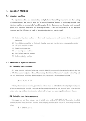
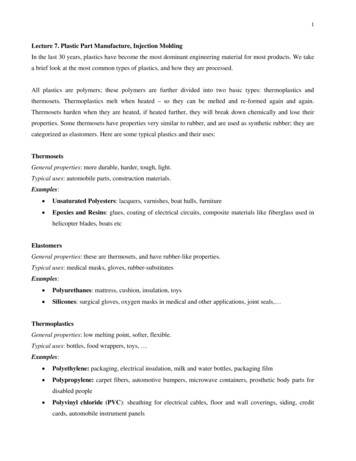
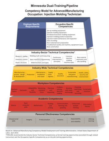
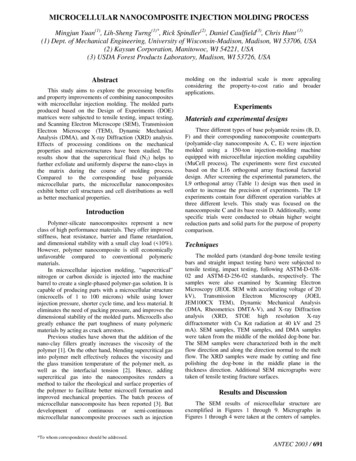
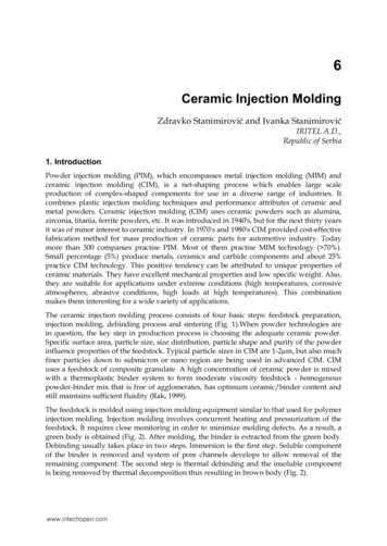
Figure 1 shows typical relative dimensions of a trapezoidalcrosssection runner. The flow through a trapezoidal runneris equivalent to that of the largest circular runner whosecross-section can be inscribed with the trapezoid.1.2.3.4.W2/3 W3/4 WLWL2/3 WCold Slug WellsDuring injection, the initial surge of material is generallycool since it has remained dormant in the nozzle while theprevious shot was being ejected from the mold. To preventthis cold material from entering the cavity and causing a visualdefect, cold slug wells or runoffs should be incorporated intothe runner system before material is allowed to enter thecavities. Properly sized runner systems designed for balancedflow which incorporate cold slug wells are show in Figure 3.1. BalancedFlow Cavities2. Cold SlugWells3/4 W1.Figure 1: Relative Dimensions of a TrapezoidalRunner for Use in a Three-plate MoldTo maintain pressure and balanced flow during injection into amultiple cavity or multigated mold, the secondary runnersshould be slightly smaller in cross section than the mainrunner. Secondary runners should be perpendicular to themain runner, and the runner junction should be vapor-honedto remove burrs and sharp edges, and contain a cold slugwell at every turn of direction. Figure 2 shows a properlysized runner system.1. SpruceLarger thanMain Runner2. SecondayRunnerSmaller thanMain Runner3. Cold SlugWell4. No ColdSlug Well5. UnbalancedFlow Lengthto CavitiesCorrect1.Undesirable5.2.3.4.Figure 2: Proper Running SizingIn addition to proper runner sizing, the layout of the mold isalso an important consideration. A runner system should bedesigned to give balanced flow to all gates, ideally designedso that the melt reaches all of the gates simultaneously.Although not recommended in certain cases, Lubrizol TPUsmay be used in a hot-runner system provided that the molddesigner has had prior successful experience in overcomingthe special problem the system represents.41.2.2.Figure 3: Runner Systems with Balanced-flowCavity Layouts and Cold Slug WellsGatesLubrizol TPUs have been satisfactorily molded througha wide variety of gate designs including fan, tab, edge,submarine and sprue. In general, the gates should have agenerous crosssectional area to allow the material to flowfreely with a minimum of pressure loss. The gates shouldbe vapor-honed with all rough edges and sharp cornersremoved. Figure 4 illustrates several acceptable gatedesigns with rounded corners for minimum restriction.1. Sprue Gate2. Fan Gate3. SubmarineGate4. Flash Gate5. Pin Gate6. Tab Gate7. Edge Gate8. Ring Gate2.1.4.6.Figure 4: Gate Designs3.5.7.8.
Tab gates are strongly recommended for the softer gradesof Lubrizol TPUs. They eliminate the distortion in the gatearea that commonly occurs with very flexible materials. Theuse of pinpoint gates and tunnel gates should be restrictedto very small parts of a few ounces or less in weight wherethe flow length from the gate is less than 5.08 cm (2 in.). Theland length or gates should always be as short as possible. Agood rule of thumb for determining the proper land length isthat it should be no greater than one half the gate thickness.In multi-gated cavities, the gate location and number ofgates are very important in relation to the appearanceand performance of the molded part. Since gate areasare almost always more highly stressed due to orientation,gates should be located in non-critical sections of thepart. Gating in thick sections of the part and allowing thematerial to flow to the thinner sections keeps sink marksto a minimum. When gating into a thick section, the flowshould be directed toward a cavity wall or deflector pinto break up the melt entering the cavity and to prevent acondition called ‘worming’. Worming is a random pattern ofweld lines opposite the gate caused by the rapid cooling ofthe injection melt. If the design of the part requires a split inthe flow front coming from the gate, a weld line will usuallyresult when the flow fronts meet. Care should be taken indesigning parts to keep the number of gates to a minimumto minimize weld lines. Multiple weld lines could detractfrom the surface appearance and may affect performance.Mold ShrinkageMold design, part design, and operating conditions all affectthe mold shrinkage value of any thermoplastic material. Incases where very close tolerance must be maintained, it issuggested that a prototype tool be made before buildingthe production tool. Where standard or coarse tolerancesare all that is required, the standard mold shrinkageallowance for the particular Lubrizol TPUs should be used.It should be noted, post annealing or exposing parts to apoint over temperature, will increase the mold shrinkagefrom what is normally expected. This data is presentedin technical data sheets of Lubrizol TPUs for molding.Ejection of the PartLubrizol TPUs release easily from properly preparedmold surfaces. Highly polished, chrome-plated surfacesshould be avoided except for simple flat parts. Becausemost parts are more complex, a vapor-honed mattesurface is recommended to provide the easiest, mosttrouble-free release. Ejector pins should have as largea surface area as possible, especially those locatedat thick part sections where the interior may still bevery soft at the time of injection. Stripper plates and airejection systems may also be used with Lubrizol TPUs.1.2.3.4.VentMold VentPlastic PartFeedRunner5. Mold CavityA. 0.001-0.002B. 0.100-0.150C. 0.500TypicalD. 0.400Minimum2.CAA1.D A4.3.BFigure 5: Mold VentingVentsVent should be cut only after initial trials on the new toolhave indicated necessary locations. A vent channel6.4 to 12.7 mm (0.25 to 0.50 in.) wide by .03 mm(0.001 in.) deep is usually sufficient. See Figure 5.THE MOLDING OPERATIONProcessing ParametersSuccessful processing of Lubrizol TPUs by injection moldingis very dependent upon a wide range of variables suchas machine size, shot size, screw geometry and molddesign. Due to these factors, exact machine conditionsfor optimum processing have to be determined by theprocessor for the system chosen. The sections that followwill define the conditions, which a molder should strive toachieve with Lubrizol TPUs. The best processing latitudeand ultimate properties in the molded part will then berealized. Finally, start-up and shutdown procedures aresummarized in the Processing Guide section. This sectionand the Trouble Shooting Guide section should be readilyavailable to set-up personnel and machine operators.To learn more, visit www.lubrizol.com/engineered-polymers.5
DryersLubrizol TPUs are fully reacted thermoplastic polyurethanematerials and will not react when exposed to atmosphericmoisture. But, as with all polyurethanes and many otherthermoplastic materials, Lubrizol TPUs must be dry whenmolded. All thermoplastic polyurethanes dissociate to somedegree when heated to a molten state in an injection-moldingmachine. They recombine when cooled in the mold. Ifmoisture is present it will interfere with the reformationand a lower molecular weight polymer will result. For asmall volume of material, an oven dryer is satisfactory. TheLubrizol TPUs should be spread in the trays one-inchdeep and dried for two hours at 105ºC (220ºF). Whenlarger volumes of material make oven drying impractical,a dehumidifying hopper dryer is recommended. A -30ºC(-20ºF) maximum dew point or a 0.02% moisture contentor less should be obtained before the material is molded.Polyurethanes are hygroscopic and will absorb moisturewhen the containers are opened to the atmosphere.The amount and rate of absorption will depend onthe type of urethane as well as the temperatureand humidity of the air to which it is exposed.Excessive moisture can also cause splay, voids,and parts sticking to the mold, and a severereduction of the service life of the part.PurgingThe machine should be thoroughly purged before and aftermolding Lubrizol TPUs. The best materials are LDPE, PEand GPPS. Lubrizol TPUs purge readily from the machine.Purging should be done immediately after the productionrun while the material is still molten. If the machine isallowed to cool to room temperature, purging can be moredifficult because the cold material will stick tenaciouslyto the screw and on reheating, is difficult to remove.Mold TemperatureMolds should be provided with good temperaturecontrol to obtain optimum appearance and productionrates. Inlet water temperatures of 7ºC to 18ºC (45ºF to65ºF) are normally used, depending on the size of thepart, wall thickness and required flow length. The ejectorside of the mold is usually maintained 6ºC (10ºF) higherthan the stationary side to facilitate part removal.6Stock TemperatureThe stock temperature can be controlled by a propercombination of the heater band settings, screwbackpressure and screw RPM. To develop ultimate physicalproperties, it is important that recommendations for stocktemperature be followed when molding Lubrizol TPUs.To measure stock temperature, use an accurately calibratedneedleprobe pyrometer. When making a temperaturemeasurement with a needle pyrometer, the molten materialshould be injected directly from the nozzle onto a piece ofheavy cardboard or some other insulating material that willnot absorb heat from the plastic. The injection pressure,injection speed and back pressure are normally at a lowersetting for taking these airshots than when at normal cycle;therefore, a stock temperature of approximately 5ºC to10ºC (9ºF to 18ºF) lower than the recommended rangeis a good objective when starting. The needle should bejabbed into the molten plastic successively four to five timesin different locations before the actual reading is taken.Occasional wiping of the needle probe with some moldrelease agent will help prevent ‘freezing’ of plastic onthe probe during the initial portion of the reading. Ifmaterial ‘freezes’ to the probe on the first insertion, it actsas an insulator on the probe’s surface and erroneouslylow values for stock temperature will be obtained.If gassing or bubbling of the hot plastic is observedduring the air-shot, it generally indicates a higher thanrecommended stock temperature is being achievedand/or excessive moisture. Stock temperature andmoisture content should be rechecked. The moltenplastic rope should appear smooth and reasonablyglossy if the stock temperature is near optimum.
Heater Band SettingsTo achieve a given stock temperature, heater bandsettings depend greatly on machine size, screwdesign and other settings such as backpressure andscrew RPM. Large machines typically yield stocktemperatures higher than the heater band settings.For the initial trial of Lubrizol TPUs an ascendingbarrel temperature profile from rear to front zones isrecommended. These settings should be adjusted toachieve an air-shot, stock temperature 5ºC to 10ºC (9ºF to18ºF) less than the final desired temperature (more heat willbe generated once the machine is cycling continuously).Since heat is being generated by the screw within thematerial, it is quite normal for the middle and front barreltemperature zones to override the set point. As long asthe machine is cycling regularly, these set points do notneed adjustments. Carefully monitor stock temperatureduring initial start-up and after any condition changes.Nozzle TemperatureThe nozzle should be controlled to the same temperatureas that of the melt. This will prevent material from settingup between shots and will not cause any degradation fromoverheating. Care should be taken so that there are no coldspots in the nozzle area. The full length of the nozzle shouldbe covered with heater bands as close to the tip as possible.Inadequate coverage by the heater bands can produce coldspots and allow some of the material to set up betweenshots. The result will be that the parts will contain lumps ofmaterial that were carried into the cavity by the melt stream.Injection SpeedA slow-to-moderate injection speed should be used at thestart of the molding run and increased to the point wherethe part fills and no signs of weld lines or sinks exist. If theinjection speed is too fast, excessive frictional heat buildupcan result in velocity burning as the material flows throughrestrictions or over sharp edges. This frictional heat can resultin surface appearance problems, or even degradation of thematerial. Injection speeds for air-shots should be relativelyslow since there is very little resistance to the material flow.A good rule of thumb for the injection speed is touse a time of two seconds per inch of ram travel.Screw RPMFor a screw of recommended geometry, a rotatingspeed of 40 to 50 RPM should be satisfactory. Largemachines generally require less RPM at optimumconditions. Due to increased diameter, a largerscrew has a greater circumferential velocity than asmaller screw at a given RPM. The greater velocitypromotes more shear heating of the molding TPU.Injection and Holding PressuresFilling the mold is best done using position transfer at 99%full during the first stage injection using velocity control. Ashort pack pressure stage at a pressure of 80% to 100%of the actual measured filling pressure is used to fill thecavity without flashing. Followed by a holding pressureto continue packing the part as it cools before the gatefreezes. The holding pressure varies with part thicknessbut typically is slightly less than the actual measured stage1 injection filling pressure. Screw should not bottom outand ¼ cushion should be maintained to accommodateany shrinkage until the gate is completely frozen.Over packing the part with excessive holding pressure ortime on the first stage injection pressure increases molded-instress that is detrimental to properties. Generally, sink marksopposite the gate indicate that more injection pressure/timeis needed. Once it is apparent that gates are frozen off, holdpressure can be reduced to save on energy consumption.A small cushion must be maintained ahead of thescrew to compensate for part shrinkage as it coolsunder holding pressure, thus preventing sink marks.Ideally, the screw should only reach full forwardposition when material movement has ceased.Cooling TimeExcept for parts with very thick sections, over 9.5mm(3/8-in.), the time required to retract the screw after theholding pressure is released is generally sufficient for coolingLubrizol TPUs. The mold can be opened immediatelyafter the screw stops. In general, the harder the TPU,the faster the set-up time. The cooling time requiredfor a 75A versus a 55D polyester TPU, for example,may be two to three times as long as that required.Screw BackpressureThe proper value for screw backpressure will vary frommachine to machine, but generally the backpressure shouldbe in the 0.3 to 0.7 MPA (50 to 100 psig) range. Lowcompression ratio screws may require back pressures.To learn more, visit www.lubrizol.com/engineered-polymers.7
SummaryIn summary, to develop the ultimate physical and appearanceproperties for Lubrizol TPUs, the material should be atthe maximum allowable stock temperature in a fully driedstate. It should be injected at a moderate speed, packedat the minimum pressure required to fill out the molddetails and allowed to relax during the cooling stage.START-UP PROCEDUREThoroughly clean the injection unit by either physicallydismantling and cleaning or by purging the barrel withpolystyrene, general purpose ABSor acrylic.Set temperature controllers and reduce injectionpressure settings, back pressure setting and screwRPM to the lower end of their operating ranges.After temperature zones have stabilized, introducethe Lubrizol TPU into the machine.Take air-shot stock temperatures and make adjustmentsto temperature settings and screw RPM to approach thedesired stock temperature. Observe the appearance ofthe molten plastic very carefully at this stage. A smooth,glossy surface is indicative of a good homogeneousmelt, while a bumpy rope and matte surface indicatenon-homogeneity and low melt temperature. A smokingor frothy melt suggests that the stock temperature istoo high or has excessive moisture. Another evidence ofgood melt temperature is the ability to draw down the hotrope into a thin monofilament. A brittle break indicatesa low melt temperature. Backpressure should be set toachieve adequate mixing and optimum melt temperature.Spray some mold release in the cavity and sprue bushingand move the nozzle into position against the sprue bushing.Start molding parts in the semi-automatic mode ofoperation while adjusting screw travel (feed) injectionpressures and injection speed to obtain a full part.Consult the Trouble Shooting Guide forcorrecting any defects in the molded part.8
TROUBIE SHOOTING GUIDEHere are some typical molding problems and several possible causes for each.PROBLEMPOSSIBLE CAUSESSink Marks or Dimpled Shot too small Holding pressure too low Holding time too short Gates too small or in wrong location Injection speed too fast Stock temperature too high Mold temperature too high Cooling time too short Sprues, runners or gates too smallShort Shots Insufficient material Injection pressure too low Injection speed too slow Cylinder temperature too low Mold temperature too low Insufficient venting Sprues, runners or gates too smallSplay Material not dried properly Melt too hot Injection too fast Gates too smallUnfluxed Granules in Part Barrel temperature profile wrong. Too cold in the rear andmiddle zones. Cold spots in the nozzle or nozzle adapter Cold spots in the hot runnerFoamy Appearance in Part Melt too hot Excessive moistureSwelling or Ballooning of Thick Sections Melt too hot Excessive moisture Cooling time too short Mold temperature too highTo learn more, visit www.lubrizol.com/engineered-polymers.9
LOCALLY PRESENTGLOBALLY NETWORKEDWith local sales and technical support, R&D and manufacturingcenters of excellence in each region, and a well-networkedglobal supply chain, we offer a convenient, single sourceof reliable solutions for customers across the world.AmericasAsiaLubrizol AdvancedMaterials, Inc.9911 Brecksville RoadCleveland, Ohio 44141-3201USAPhone: 1 888-234-2436Lubrizol Management(Shanghai) Co., Ltd.10F, Park Center International1088 Fang Dian RoadShanghai PRC 201204Phone: 86-21-38660422Europe, Middle East,India & AfricaLubrizol Advanced MaterialsEurope BVBAChaussée de Wavre 19451160 Brussels, BelgiumPhone: 32 (0) 2-678-1911To learn more, contact us at engineeredpolymers@lubrizol.com.The SELLER MAKES NO WARRANTIES, EXPRESS OR IMPLIED, INCLUDING, BUT NOT LIMITED TO, THE IMPLIED WARRANTIESOF MERCHANTABILITY AND FITNESS FOR A PARTICULAR PURPOSE. Nothing contained herein is to be considered as permission,recommendation, nor as an inducement to practice any patented invention without permission of the patent owner. 2018 The Lubrizol Corporation. All rights reserved.All marks are the property of The Lubrizol Corporation. GL-EP-18-113786contact us athttp://go.lubrizol.com/EP
Lubrizol’s portfolio of injection molding grades includes . injection pressure minimizes the possibility of producing highly stressed parts. This is significant because many new thermoplastic polyurethane molded par