Transcription
1Lecture 7. Plastic Part Manufacture, Injection MoldingIn the last 30 years, plastics have become the most dominant engineering material for most products. We takea brief look at the most common types of plastics, and how they are processed.All plastics are polymers; these polymers are further divided into two basic types: thermoplastics andthermosets. Thermoplastics melt when heated – so they can be melted and re-formed again and again.Thermosets harden when they are heated, if heated further, they will break down chemically and lose theirproperties. Some thermosets have properties very similar to rubber, and are used as synthetic rubber; they arecategorized as elastomers. Here are some typical plastics and their uses:ThermosetsGeneral properties: more durable, harder, tough, light.Typical uses: automobile parts, construction materials.Examples: Unsaturated Polyesters: lacquers, varnishes, boat hulls, furniture Epoxies and Resins: glues, coating of electrical circuits, composite materials like fiberglass used inhelicopter blades, boats etcElastomersGeneral properties: these are thermosets, and have rubber-like properties.Typical uses: medical masks, gloves, rubber-substitutesExamples: Polyurethanes: mattress, cushion, insulation, toys Silicones: surgical gloves, oxygen masks in medical and other applications, joint seals, ThermoplasticsGeneral properties: low melting point, softer, flexible.Typical uses: bottles, food wrappers, toys, Examples: Polyethylene: packaging, electrical insulation, milk and water bottles, packaging film Polypropylene: carpet fibers, automotive bumpers, microwave containers, prosthetic body parts fordisabled people Polyvinyl chloride (PVC): sheathing for electrical cables, floor and wall coverings, siding, creditcards, automobile instrument panels
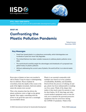
2 Polystyrene: disposable spoons, forks etc., also used to make Styrofoam (soft packaging material) Acrylics (PMMA: polymethyl methacrylate): paints, fake fur, plexiglass Polyamide (nylon): textiles and fabrics, gears, bushing and washers, bearings PET (polyethylene terephthalate): bottles for acidic foods like juices, food trays, mylar tapes PTFE (polytetrafluoroethylene): non-stick coating, Gore-Tex (raincoats), dental floss.The most common methods of processing plastics to manufacture plastic parts are similar to methods we havelearnt for metals and glass. These include Extrusion, Injection molding, Blow molding, Casting, etc. Amongthese, perhaps injection molding is the most significant for local industry – almost all manufacturingcompanies use parts that are injection molded, whether they make toys, home-appliances, electronics orelectrical parts, watches, computers, etc.7.1. Plastic ExtrusionExtrusion can be used for thermoplastics. The raw material is in the form of pellets ( 10mm sized pieces),granules ( 5 mm), or powder. Extrusion machines are used to make long pieces of constant cross-section. Thecross-section geometry can be solid or hollow, and may be quite complex in shape. Usually, extruded partsare used as raw stock for use in manufacture of other products (e.g. channels on the sides of windows, etc.You can find plastic extruded parts in many bathroom and kitchen fittings). Figure 1 shows a typical extrusionmachine. Figure 2 shows some examples of extruded shapes.Figure 1. Extrusion machine schematic [source: Kalpakjian and Schmid]
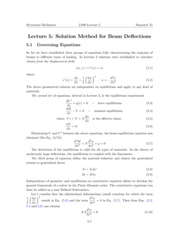
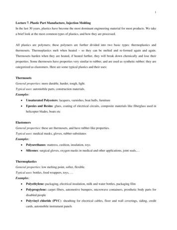
3open cross-sections (channels)closed cross-sections (tubes, pipes)pelletsFigure 2. Parts made by extrusion [sources: websites of keltrol.com, seilerpc.com]The main difference from metal extrusion is the mechanism for pumping out the molten plastic: plasticextrusion uses a large screw in a cylinder, which simultaneously mixes, and pushes the pellets/granulestowards the die; along the way, the heating chamber melts the plastic.Interesting note: many plastic processes use plastic pellets as raw material; these pellets are the shape of shortcylinders, which are themselves formed by plastic extrusion.7.2. Blow MoldingThis process is almost identical to the blow-molding of glass that we studied earlier.7.3. ThermoformingIn thermoforming, a sheet of plastic is used to cover a shape (e.g. a die) by heating the sheet till it is semifluid, and then pulling it over the die using vacuum suction (this method is called vacuum forming). In analternate form, called pressure forming, the pressure is applied using high pressure air from above the plasticsheet. This process is most commonly seen in packaging of food, toys etc.; it is also used to make appliancehousings, etc. The following schematic shows different types of thermoforming.Figure 3. Schematic of thermoforming processes [source: Kalpakjian and Schmid]
4(a) plastic sheet loaded into frame(b) frame slides out above mold(c) heated mold is raised, forming convex shapes(d) vacuum lines pull the plastic into concave ‘holes’(e) frame returns to reload; mold lowered; part removedFigure 4. Stages in a vacuum thermoforming process [source: www.ymlf.com.hk]The advantage of thermoforming is that the tooling (usually made by machining Aluminum) is cheap toproduce. The vacuum forming process leaves tiny marks where the mold has holes for vacuuming out the air;these holes are made small, e.g. 0.5mm. The main quality control issues include non-uniform thickness ofparts, warping of parts when they cool, and tearing of the sheet. The figure below shows images of parts thatcan be made using thermoforming processes.
5Figure 5. Thermoformed parts7.4. Compression and Transfer MoldingThese two processes are used mostly for thermosetting polymers. In compression molding, the raw material isplaced inside the mold in semi-solid or solid (i.e. as granules, or a single piece called a plug). The mold isheated and closed using pressure, and the plastic flows to fills the cavity. Excess material may leak out fromthe parting lines creating flash, which must be trimmed away.If the part shape is more complex, transfer molding may be used. Here, the charge (thermoset grains) areplaced in a heated cylinder till they are soft; a hole at the bottom of the cylinder is connected to the die cavityby a sprue. A plunger pushes the semi-solid plastic into the die through the sprue, using high pressure.These methods are used to make dishes, handles for cooking pots, skis, housing for high-voltage switches,some rubber parts like shoe soles, and even composites such as fiber-reinforced parts. These processescommonly used with thermosetting polymers, where the initial charge is in semi-solid state (partialpolymerization), and the heating causes the plastic to set as it forms the shape of the mold.
6Figure 6. A compression molding machineFigure 7. Schematic of Compression MoldingFIGURE 8. Schematic of Transfer Molding
77.5. Injection MoldingInjection molding is perhaps the most common and important of all plastic processing processes. The processis extremely versatile, and can produce very complex shaped parts, with the use of multi-sided molds. Evenparts with metal inserts can be produced. While injection molding dies are expensive to produce, each die canbe used to make tens of thousands of components at very rapid rate, so that per-part cost is very low. Thesimplest form of injection molding is shown in the schematic below.Figure 9. A simple reciprocating screw injection molding machine [source: www.offshoresolutions.com]Figure 10 shows the cycle of operations during production of a molded part. The moving platen puts the moldtogether; the mold halves are held with large force, and the molten charge is forced into the cavity; the plasticsolidifies, and finally, the moving platen is retracted, and ejector pins in the mold push the part out.Figure 10. Cycle of operation for injection molding [source: www.offshoresolutions.com]
8Just as in die casting, the mold is specially made for each part, and the basic elements of each mold are thesame, including sprue, gates, runners and vents; in addition, the location of ejection pins is usually specifiedin the mold design, since there points have visible marks (therefore ejection is usually done from the coreside, and is usually mounted into the mold half mounted on the moving platen). The cavity is divided betweenthe two mold halves in such a way that the natural shrinkage of the molding causes the part to stick to themoving half. When the mold opens, the ejector pins push the part out of the mold cavity. We look at thedetails of molds in more detail below.Two-Plate Mold: This consists of two halves fastened to the two platens of the molding machine's clampingunit. When the clamping unit is opened, the mold halves separate. Molds can contain one multiple cavities toproduce one or multiple parts in a single shot (last example in figure 11 below). The parting surface is thesurface shared by the two mold halves.Figure 11. Examples of Injection Molding Parts [source: www.ylmf.com.hk]The cooling system is made up of passages in the mold that are connected to an external pump. Water iscirculated through them to remove heat from the hot plastic. The air trapped in the cavity passes through thesmall ejector pin clearances in the mold, and through narrow vents that are machined into the parting surface(typically about 0.03 mm deep and 12 to 25 mm wide).Three-plate mold: This design (see figure below) has some advantages. The molten plastic flows through agate located at the base of the cup-shaped part, rather than at the side. This allows more even distribution ofmelt into the sides of the cup. In the side gate design in the two-plate the plastic must flow around the coreand join on the opposite side, possibly creating a weakness at the weld line. Secondly, the three-plate moldallows more automatic operation of the molding machine. As the mold opens, the three plates separate; this
9forces the runner to break from the parts, which drop by gravity or using air-blower into collecting containersput under the mold.Figure 12(a). A two-plate moldFigure 12(b). A three-plate moldMolds with cores/cams: Many injection molded parts have some part of the geometry that is inaccessible toeither of the mold halves. Such regions must be created by means of extra moving parts in the mold. Figure13 below shows a cup-shaped part with a through-hole. One method to mold this part is by the use of a core.The figure below shows the steps of the mold opening. Figure 14(a) shows a more complex mold with fourside action cams. Typical side-action cam design is shown in Figure 14(b); the top (red) part is connectedwith the bolt on top to the moving platen. As the mold opens, the green part is forced to slide to the right. Themold-piece that creates the insert geometry is attached to the green piece by the blue bolt.
10(a) moving platen opens(b) core is pulled out (side action)(c) part ejected from moldFigure 13. Injection molding a part with side action using coreFigure 14 (a). A mold with four side action cams (b) The operation of side action camsInjection Molding ConsiderationsSteps in designing an Injection MoldThe design of injection mold tooling requires several steps. The molding directions will determine thenumber of inserts/cams required, which severely affects the cost of the tooling. After finding the suitablemolding direction, the parting lines are determined. The parting planes form the surface of the mold halves –usually, the parting planes are formed by extending the parting line outwards, perpendicular to the moldingdirection. The gating design determines where to locate the gate(s). If a multiple cavity mold is made, therelative positions of the multiple parts is determined. The runners are designed, and sprue is located. Thenthe functional parts of the mold are created next – this includes the part ejection system, systems to eject thesolidified runners etc. Finally, the alignment rods that will keep all mold components aligned during
11operation are designed. The following figures show a simple example for molding a cup. Figure 15 shows acup-shaped part. There is only one possible parting line (why ?). The ideal parting surface for this line is aplane. Figure 16 shows the stages of development of the mold. Note that here a plate is used to eject the cup,rather than ejection pins [Exercise: comment on this choice].cupparting lineparting planeFigure 15. A simple avitycavitycorecore(a)knob(c)(b)core(d)Figure 16. Stages of development of the injection vityPartPartStripperplateFigure 17. The mold in operation
12Finally, we consider some more complex shape features in injection molded parts. Some such typical featuresare shown in the figure below.Figure 18. Examples of different shape features in typical injection molded parts [source: www.idsa-mp.org]In some cases, by the use of non-planar parting lines, we may be able to create the shape with 2-piece molds(i.e. without the use of side action cams). An example of this is the mouse hole. In fact, even the shut-off holemay be created without side action, as shown in the figure below. In other cases, (e.g. to create the holes forthe vents in the figure above) a side action cam is required.(a) Shut-off hole:no side action required(b) Latch:no side action required(c) Angled Latch:Side action cam requiredFigure 19. Examples of molds with complex parting lines, and a multi-part mold
13Considerations in design of injection molded partsThere are several geometric and design considerations for parts manufactured using injection molding. Manyof these considerations have resulted in a large set of guidelines for geometric features in the design. The twobiggest geometric concerns are (i) proper flow of the plastic to all parts of the mold cavity before it solidifies,and (ii) shrinking of the plastic resulting in sink holes. Some examples of the first concern include: if the partthickness is too small, plastic flow is restricted due to high friction; if the gate is too far away from somesmall features of the geometry, or is there is a constriction in the path along which the plastic will flow;another guideline is that the cross section of the part should not change abruptly, since this leads to poor flow.Regarding the second concern, guidelines include (a) maintaining uniform cross-section thickness throughoutthe part; use of ribs and gussets to provide mechanical strength instead of using thicker sections etc. Figure 20shows a comparison of strength of parts of the same length but different cross-sections – the examplesdemonstrate that the use of ribs will result in lighter parts for a given stiffness. Figures 21-23 belowdemonstrate some of the guidelines for common molded geometry.Figure 20. Comparison of breaking stress under bending moments on bars of different cross-section geometry
14Figure 21. Guidelines for rib dimensionsFigure 22. Molding problems (sink holes and voids) occur if the part has thick sectionsFigure 23. Example of improving design for injection molded partsThe main ejection-related guideline is the same as for all casting/molding processes: providing for taperedshapes by applying a draft angle to all part surfaces with normal vector perpendicular to the moldingdirection.Another consideration in injection molding is regarding weld lines. As the plastic flows to fill the mold, thereare some regions where the advancing front of the plastic flowing from different directions meets. At thispoint the two flows mix together – however, the solidified plastic has slightly less strength along the linewhere this occurs. Lines along which this happens are called weld lines. An example is shown in the moldingof a phone cover plate in Figure 24 below.
15gateWeld lineFigure 24. Due to location of the gate and the geometry of the cavity, the front of the flowing plastic meetsalong several lines, called weld linesAPPENDIX: Common plastics and their usesAcrylonitrile-Butadiene-Styrene (ABS) A class of thermoplastic terpolymers including a range of resins, allprepared with usually more than 50% styrene and varying amounts of acrylonitrile and butadiene. The threecomponents are combined by a variety of methods involving polymerization, graft copolymerization, physicalmixtures and combinations thereof. Typical applications are found in appliances, automotive parts, pipe, andbusiness machine and telephone components.Polycarbonates (PC) Group of clear, thermoplastic polymers used mainly as molding compounds.Polycarbonates are prepared by the reaction of an aromatic difunctional phenol with either phosgene or anaromatic or aliphatic carbonate. The commercially important polycarbonates use 2,2-bis (4-hydroxyphenol)propane (bisphenol A) and diphenyl carbonate. This polymer is a clear plastic with a slight yellow discoloration. Ithas excellent electrical properties and a high impact strength.Low & High Density Polyethylene (PE) Widely used plastic. It is a polymer of ethylene, CH2 CH2, having theformula (-CH2-CH2-)n, and is produced at high pressures and temperatures in the presence of any one ofseveral catalysts, depending on the desired properties for the finished product. Polyethylene is resistant to water,acids, alkalies, and most solvents. Its many applications include films or sheets for packaging, shower curtains,unbreakable bottles, pipes, pails, drinking glasses, tubing, and insulation for wire and cable.Polypropylene (PP) Plastic noted for its lightweight, being less dense than water; it is a polymer of propylene. Itresists moisture, oils, and solvents. Since its melting point is 121 C (250 F), it is used in the manufacture ofobjects that are sterilized in the course of their use. Polypropylene is also used to make textiles, coating of wireand cable, packaging material, tubing, and trim molding.Polystyrene (HIPS) Widely used plastic; it is a polymer of styrene. Polystyrene is a colorless, transparentthermoplastic that softens slightly above 100 C (212 F) and becomes a viscous liquid at around 185 C (365 F).It is resistant to acids, alkalies, oils, and alcohols. It is produced either as a solid or as a foamed plastic marketedunder the trade name Styrofoam. Its many uses include electrical and thermal insulation, translucent window andsignage panels, storage-battery cases, toilet articles, and display signage.Polyvinyl chloride (PVC) Thermoplastic that is a polymer of vinyl chloride. Resins of polyvinyl chloride are hard,but with the addition of plasticizers a flexible, elastic plastic can be made. This plastic has found extensive use asan electrical insulator for wires and cables, tubing, gaskets, and trim molding.Provista/PETG A clear thermoplastic copolymer (copolyester) with high melt strength used mainly for profileextrusion. Provista/PETG is often used as a replacement for Acrylic due to cost and ease of processing. It has
16excellent chemical resistant and high clarity. It is also UV resistant and is FDA compliant for food contactapplications. It's many uses include display signage, tubing, trim molding, and clear window panels.Thermo Plastic Elastomers (TPE) Diverse family of rubber like materials that, unlike vulcanized rubber can beprocessed like thermoplastic materials. TPE's are used in a variety of applications in the automotive,construction, medical, food and beverage, electrical, appliance and electronic markets.
7.5. Injection Molding Injection molding is perhaps the most common and important of all plastic processing processes. The process is extremely versatile, and can produce very complex shaped parts, with the use of multi-sided molds. Even parts with metal inserts can be produced. While injection mol