Transcription
Production of Injection Molding Tooling with Conformal CoolingChannels using The Three Dimensional Printing ProcessEmanuel Sachs 1, Samuel Allen2, Michael Cima2, Edward Wylonis 1, and Honglin Gu0 21Department of Mechanical Engineering2Department of Materials Science and EngineeringMassachusetts Institute of TechnologyCambridge, Massachusetts 02139Abstract - Three Dimensional Printing is a desktop manufacturing process in whichpowdered materials are deposited in layers and selectively joined with binder from an ink-jet styleprinthead. Unbound powder is removed upon process completion, leaving a three dimensionalpart. Stainless steel injection molding inserts have been created from metal powder with the 3DPprocess.The freedom to create internal geometry by the use of the 3D-Printing process allows for thefabrication of molds with complex internal cooling passages. Tooling was developed with coolingchannels designed to be conformal to the molding cavity. A finite difference simulation wasconstructed to study conformal channel design.A direct comparison of the mold surface temperature during the injection cycle of a 3D Printedmold with conformal channels and a mold machined with conventional straight channels wascompleted. The conformal passages produced with the 3DP process provide the ability toaccurately control the temperature of the molding cavity throughout the process cycle. Surfacetemperature measurements demonstrated that the inserts with conformal cooling channels exhibiteda more uniform surface temperature than the inserts machined with straight channels.Issues such as powder removal and post processing of green parts with small coolingchannels were investigated.I. INTRODUCTIONA. MotivationThe injection molding process is one of the most widely used methods of manufacturingpolymer plastic products. Many parts that are injection molded today have very rigid tolerancerequirements. Proper thermal management of metal injection molding tooling is necessary toincrease part quality and production rates. Cooling passages placed in the tooling manage the heatflow out of the plastic. Current fabrication methods place severe limitations on the configuration ofthe cooling channels used for heat withdrawal.The freedom to create internal geometry by the use of the 3D-Printing process allows for thefabrication of molds with complex internal cooling passages. These cooling channels can bedesigned to be conformal to the molding cavity. Conformal passages produced with the 3DPprocess provide the ability to control more accurately the temperature of the molding cavitythroughout the process cycle. Such temperature control has the potential to produce parts withlower residual stresses and to shorten cycle times.448
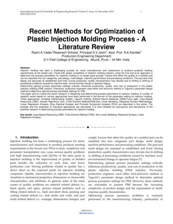
B. Current Mold Cooling PracticesCooling in cavity geometries is typically accomplished by routing straight cooling channelsaround the part cavity. The cooling circuits are positioned around the part cavity as uniformly asthe part shape will allow and as close to the cavity walls as possible. The number and size of thecooling circuits are often limited by the part's ejector system. Often, it is not possible to placecooling channels in the inserts. Channels must be placed in the bolsters or support blocks instead.In this case the interface between the bolster and the insert is critical. A thin layer of air at thisinterface can act as an insulator and hinder heat withdrawal. Short and independent routings yieldthe best temperature control performance. Parallel cooling circuits as opposed to series coolingcircuits are considered a better cooling method. Short parallel circuits do not allow the coolant toheat up in the mold and offer more consistent and uniform temperature control [Gordon, 1993].Cooling of the core insert is the greatest problem in most injection molding applications.Often, no cooling is employed in the core itself. Cooling only occurs in the mold base through thecore mount. With no core cooling, eventual heating of the core is unavoidable.Cooling of slender cores is often accomplished by using inserts made of materials with highthermal conductivity, such as copper, beryllium-copper or high-strength sintered copper-tungstenmaterials. [Menges, 1993] These metal inserts are press-fitted into the slender core and extend intothe mold base. The high thermally conductive insert usually extends into the flow of coolant in acooling channel. A major concern in utilizing this core cooling method is maintaining an extremelytight press-fit. If there is a poor fit, the resulting thin layer of air between the high thermallyconductive insert and the hole in the core will act as an insulator to heat transfer.A baffle is a common cooling method in those cases in which coolant is directly channeledthrough the core. A baffle usually employs a flat or spiral divider in a hole running through thecenter of the core. The inlet and return flow is separated. This method provides maximum crosssections for the coolant to flow through. The divider must be mounted exactly in the center of thehole to ensure that the coolant does not bypass the hole.The most effective cooling of slender cores is achieved with bubblers. An inlet tube directsthe coolant into a blind hole in the core. The diameters of both have to be adjusted in such a waythat the resistance to flow in both cross sections is equal. Bubblers are commercially available andare usually screwed into the core. One problem with baffles and bubbler cooling systems is that thenecessary hollow center can result in a structurally weak core insert. [Menges, 1993]C. Three Dimensional Printing - Application to Injection Molding ToolingThree Dimensional Printing (3DP) is a process for the rapid fabrication of three dimensionalparts directly from computer models [Sachs et aI, 1990]. A solid object is created by printing asequence of two-dimensional layers. The creation of each layer involves the spreading of a thinlayer of powdered material followed by the selective joining of powder in the layer by ink-jetprinting of a binder material. A continuous-jet printhead is raster scanned over each layer ofpowder using a computer controlled x-y table. Individual lines are stitched together to form 2Dlayers, and the layers are stitched together to form a 3D part. Unbound powder temporarilysupports unconnected portions of the component, allowing overhangs, undercuts and internal449
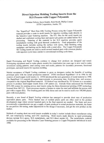
volumes to be created. The unbound powder is removed upon process completion, leaving thefinished part. The 3D Printing process sequence is shown in Fig. 1.o.!,I:AitiK··:: : ::::: . '0zSpread Powder1.-Print Layer tDrop PistonRepeat Cycle - - - - - - - - - - - - - - 'Fig. 1. The 3D Printing sequence.3D Printing was initially developed for the production of ceramic shells and cores to be laterused for the casting of metal parts. In this embodiment of the process, alumina powder is spreadinto the powder piston and selectively bound using colloidal silica as a binder. After completion ofprinting, the part is fired in a furnace to further bond the silica to the alumina and strengthen thepart sufficiently so that it can be used as a ceramic mold. [Sachs, 1992]An important aspect of the 3D Printing process its inherent flexibility with respect to materialssystems. Although developed around alumina powder and silica binder, many types of powdersand binders may be used. This research effort employs the 3D Printing process for the directfabrication of metal injection molding tooling with conformal cooling channels. Stainless steel(316L) powder is selectively bound with a latex emulsion binder using the 3DP process resultingin a green part. A series of post-processing steps similar to those found in powder metallurgyprocessing are used to obtain all-metal injection molding tooling with conformal cooling passages.Detailed information on the specific exploration of the application of 3D Printing to the productionof metal parts and injection molding tooling is provided by Michaels. [Michaels, 1995]II. FABRICATIONA. IntroductionThe overall process of creating a metal part may be divided into several steps. First, the greenpart is printed using the 3DP system by using a temporary organic binder. Powder must then beremoved from the insert cavities and cooling channels. The green part is then subjected to a seriesof post processing steps.450
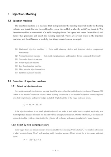
The first step in post-processing the green part is to debind and sinter the part. In debinding,the organic binder used in the 3D Printing process thermally decomposes in an inert gas furnace.Metal skeletons have sufficient strength to be handled after debinding, however, it is advantageousto sinter the part in the same firing schedule at a higher temperature to increase its strength.Finally, the part is infiltrated with a lower melting point alloy to 100% density.B. Printing Green Tooling InsertsThe powder used in creating green 3D Printed tooling was a 316L spherical stainless steelpowder with a size range of 60 flm from Anval Corp. of Rutherford, NJ. An aqueous acryliccopolymer emulsion (Acrysol) from Rohm and Haas of Philadelphia, PA was used as the binder.Typical packing density of the printed part is approximately 60%. A typical 3DP green part is 10%by volume binder, leaving approximately 30% open porosity.After completion of the printing process the entire powder bed is allowed to air dry for aperiod of 24 hours. The inserts are then placed in an oven at 100 C for one to two hours tocompletely cure the acrylic binder. The green part is then removed from the powder bed. Theremaining attached powder on the exterior of the insert is easily blown off with compressed air.Fig. 2 is a photograph of a large tooling insert in the green state and final infiltrated state.Fig. 2. A large 3D Printed tooling insert in the green (left) andfinal - infiltrated (right) states.45]
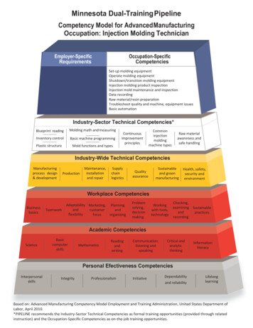
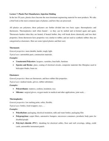
C. Powder Removal from Conformal Cooling ChannelsAfter printing, complex cavities and cooling channels of the green metal part must be clearedof powder. In order to test the ability to remove powder from complex passages a powder removaltest shell was designed. This experiment was devised to evaluate the minimum size cooling channelthat could be cleared of powder. A thin box shaped shell was designed such that it could be easilysplit open and the contents of the channels could be viewed. One of the middle layers of the partcontains only thin connection lines that were printed between the channels and around the perimeterof the shell. The lines printed between the channels prevent powder from jumping from onechannel to the next during powder removal. The line printed around the perimeter of the part aidsin securing the top of the shell to the bottom. Because only these few lines fasten the top of theshell to the bottom, this weak layer acts as a delamination layer providing easy separation of the topof the shell after the powder removal experiment has been conducted. Fig. 3 is a schematic of thefive centimeter long test shell containing three straight channels and one zig-zag channel.smallest channel in the shell has a nominal channel width of 525 flm. The middle channel is 875flm wide, and the largest channel and the zig-zag channel are 1.225 mm wide. All channels are 2mmdeep.25 mm 5 mm1.25 mm x 2 mm0.89 mm x 2 mm0.53 mm x 2 mmFig. 3. Schematic of opened powder removal test shell.The method used to clear the test shell involves placing the green part in a bath of water. Thispowder removal technique adds a requirement that the polymeric binder in the green part be able towithstand water immersion for a period of time without resulting in distortion of the green part.Fig. 4 shows a picture of a powder removal shell cleared using the water bath procedure.channels were cleared using this technique and the green part suffered negligible distortion.452
Fig. 4. Opened powder removal test part cleared with soda water vacuumpowder removal procedure.D. Debinding and Sintering ofGreen 3D Printed InsertsAfter printing and powder removal, the part is processed using techniques similar to thoseused in metal injection molding (MIM) with the advantage that the green part has open porositywhich greatly facilitates the removal of binder. In debinding, the organic binder used in the 3DPrinting process thermally decomposes in an inert gas furnace. Metal skeletons have sufficientstrength to be handled after debinding, however, it is advantageous to sinter the part in the samefiring schedule at higher temperature to increase its strength.Debinding and sintering was executed in an Argon / 5% Hydrogen atmosphere tube furnace.The binder polymer chains are broken by heating during thermal decomposition and the binder isevolved as a gaseous product. Firing yields parts with a final density of 64% of theoretical. Adimensional change of approximately -1.5% is exhibited in large tooling inserts.III. MOLD DESIGN AND TESTINGA. How Close is Close EnoughA useful guide to the design of conformal cooling channels is a consideration of how closethey have to be to the surface to exert significant influence over the temperature at the surface of themolding cavity. If we consider that prior to injection, the tool is at a uniform temperature equal tothe coolant temperature, we see that the first portion of heat conducted into the tool will go towardwarming up the portion of the tool which lies between the surface and the cooling passage. Thisobservatioin can be used as the basis of a I-dimensional model which provides guidance to coolingpassage placement.453
Consider a I-D heat flow in a tool where the distance from the mold surface to the closest partof the cooling channel is d. Let us assume that when the plastic is first injected, the surface of thetool quickly rises to the melt temperature, T m. If the tool where under a steady state condition, alinear temperature profile would develop droping from Tm at the surface to T c, the temperature ofthe coolant at the passage. If no heat is removed by the coolant, the amount of heat that must beconducted into the tool to reach this condition is:Heat flow into tool per unit area pCpd( Tm Tc 2Tc ) pCpd Tm -2Tc(3)where p, and cp are the density and specific heat of the tool material respectively.of the toolmaterial and it is assumed that the tool materail between the surface and the channel reaches atemperature which is an average of T m and T c. This heat must be conducted into the tool by a heatflux which may be approximated as:Heat flux per unit areaThe time required to warm up the tool,equation (4) :"C k TmdTc(4)can now be calculated by dividing equation (3) by(5)In order to funciton as a conformal cooling channel, "C must be significantly less that the cycletime, "Ccycle of the tool which leads to the condition:d (6)where a is the thermal diffusivity of the tool material.For a typical cycle time of 10 sec and using the thermal diffusivity of the 3D Printed toolmaterial (0.6 x 10⁻⁵ m 2/s), we can calculate the condition d 8mm as the requirement for a channelto behave as a conformal channel.B. Design ofExperimental InsertsA ring shaped geometry was chosen for the plastic part design. A gap in the ring wasdesigned to demonstrate clearly any distortion in the part. It was designed such that residual stressbuildup in the part would exhibit itself in the form of the ring gap opening or closing. The ringshape is applicable to a core / cavity design that is simple enough to be modeled. A schematicdrawing of the simple ring geometry is shown in Fig. 5 below.454
0.0625 in.--.-.11.ITf-ool-0.75 inI- I 14-- 0.085 in.GapI (A)1.5 in. I1(B)Fig. 5. Isometric (A) and cross-section (B) schematics of polystyrene part geometryThe cavity insert is a rectangular block having a length of 3.5 inches, width of 3.0 inches andheight of 1.5 inches. Fig. 6 describes the basic features of this insert. The cavity insert wasdesigned to fit in a slot milled in a Modular Unit Die (MUD) frame assembly block. A 1.5 taperedend mill was used to apply draft to the cavity wall for easy part release. A standard sprue-runnergate system was employed. The gate machined in the top face of the insert was 0.032 inches wideand 0.032 inches deep. Three thermocouple holes were drilled next to the cavity wall for surfacetemperature measurement.The core insert consists of a rectangular base with a cylindrical shaped core. The rectangularbase has a length of 3.5 inches, width of 3.0 inches and a height of 0.5 inches. Fig. 7 describesthe basic features of this insert. The cylindrical shaped core sticks out of the top of the rectangularbase. The wall of the core has a 1.5 taper matching the draft angle of the cavity wall. Again, thisdraft angle ensures easy release of the plastic part from the core.0The cylindrical core was designed with a rib to create the gap in the ring geometry. Two flatparallel walls were required for ease of gap width measurement. Thus, the rib on the core insertwas machined such that the two walls of the rib were parallel. Three thermocouple holes weredrilled next to the core wall for surface temperature measurements.The mold assembly utilizes a pair of mild steel assembly blocks in a MUD frame. Recesseswere milled in the assembly blocks to accommodate the two inserts. A simple ejector plate / returnspring assembly was used for the ejector system.The first inserts made were created from 303 stainless steel. This material was selectedbecause it offered the best match of thermal conductivity with 3D Printed 316L stainless steelinfiltrated with bronze while offering relatively easy machining. The thermal conductivity of the303 stainless steel is 16.5 W/m-oC [Lyman, 1961] and the experimentally determined thermalconductivity of the 3D Printed material is 22 W/m- 0c.Core and cavity inserts were machined from 303 stainless steel. Conventional straight coolingchannels were machined in these inserts for experimental comparison with the 3D Printed insertshaving conformal cooling channels. The diameter of the channels drilled in the 303 stainless steelinserts were designed to have the same cross sectional diameter as the conformal channels in the3D Printed inserts. A cooling channel cross sectional diameter of 4.76 mm was chosen.455
Thermocoupleholes0Sprue pullerpin hole1.5 Taperedcore wallRibEjector pinholes (6)Fig. 8. Cavity insert design.Fig. 9. Core insert design.Two straight channels were drilled in the cavity insert as shown in Fig. 8(A). These channelswere drilled in-between the cavity wall and the sprue. The two channels were spaced evenly alongthe depth of the cavity. Fig. 8(B) depicts channel placement in the core insert. Three straightchannels were drilled in the rectangular base of the insert below the actual core. Placement ofcooling channels in these inserts was limited due to the ejector pin placement.Tapered Core(1.5 degrees)SpruePullerPin HoleCore Rib toCreate Gap InRing(A)(B)8. Cooling channel placement in the 303 stainless steel cavity (A)and core (B) inserts.Fig. 9 depicts the infiltrated and machined 3D Printed cavity and core inserts with conformalcooling channels. A polystyrene ring molded with these inserts in also shown. Schematics of thecooling channel placement in these inserts are shown in Fig. 10. Fig. 11 is a photograph of two3D Printed infiltrated core inserts. One insert has been cut open to reveal the conformal channelsinside.456
Two separate conformal channels were designed in the 3D Printed cavity insert. Each separatechannel splits 3.18 mm from the cavity wall into two channels, well below the 8mm calculatedusing equation (6) above. These two channels follow the circular shape of the cavity wall andconverge to one exit channel. This channel placement forms a torus shaped passage surroundingthe molding cavity. This torus shape keeps the channels 3.18 mm from the molding surface alongthe entire perimeter of the cavity. All channels are circular in cross-section and have a diameter of4.76 mm matching the straight channels in the 303 stainless steel inserts. The two torus shapedchannels were spaced evenly along the depth of the cavity.As in the 3D Printed cavity design, two torus shaped channels were horizontally spaced alongthe height of the core. Again, the torus shape keeps the channels 3.18 mm from the moldingsurface along the entire perimeter of the core. A single horizontal channel open on the side of thebase of the insert connects with a vertical channel underneath the core. This vertical channelintersects the two torus shaped channels. An identical channel path on the opposite side of the coreprovides a channel exit.Fig. 9. Infiltrated and machined 3D Printed inserts with conformal cooling assages(B)(A)Fig. 10. Cooling channel placement in the 3D Printed cavity (A) and core (B) inserts.457
Fig. 11. Infiltrated and machined 3D Printed core insert (right) and an infiltratedcore insert that has been cut open to reveal the conformal cooling channels. (left)Conformal channel placement in the 3D Printed inserts was designed based on the order ofmagnitude calculations discussed previously. This design simply places the conformal channels aconstant distance (3.18 mm) from the molding surface.In order to measure the temperature of the molding surface, three thermocouples were placedin the cavity and the core inserts. Thermocouple holes 1.5 mm in diameter were drilled such thatthe closest edge of the hole was less than 0.38 mm from the mold surface at the mid point of theheight of the ring. One thermocouple was placed near the gate, one near the rib and one inbetween the gate and the rib. The thermocouples were placed in the holes with a highly thermallyconductive paste. Fig. 12 depicts a cross-section of the mating core and cavity inserts.C. Experimental DesignExperimental results focus on a comparison between the mold surface temperature of theinserts with straight channels and the 3D Printed inserts with conformal channels. An EngelEC88, 30 ton injection molding machine located at MIT was used to mold the polystyrene partswith the stainless steel inserts and the 3D Printed inserts. Melt temperature and injection holdpressure were 215 C and 1000 psi, respectively in all experiments. An injection speed of 1.8 in/secwas used. Approximately 25 - 30 polystyrene parts were injection molded in a single run.Temperature data was recorded from the six thermocouples placed near the molding surface. Twowater reservoirs were used to maintain a constant coolant temperature and were connected to apressurized nitrogen tank. The reservoirs were connected in parallel to the core and cavity insertsto provide a flow rate of 1.3 gal/min through each insert.458
Cavity ConformalCooling ChannelCore ConformalCooling ChannelRib ThermocoupleHoles.AMold Material ConformalCooling ChannelGate s inConformalchannels incavity insertThermocouplebeadParting LineThermocouple - - -.wiresSection A-AFig. 12. Thermocouple placement in cross sections of the core and cavitymold pair forming the mold cavity. (Two drawings are of different scale)D. Mold Suiface Temperature ResultsMold surface temperature measurements were obtained for the 303 stainless steel inserts withstraight channels and the 3D Printed inserts with conformal channels. The coolant temperature wasapproximately 11 C in all injection molding runs. A cycle time of approximately 11 seconds wasused for all experiments. This cycle time was chosen based on the minimum cycle time that could459
be obtained using the inserts with straight channels. A slightly shorter cycle time was possibleusing the inserts with conformal channels, however, for comparison with the straight channelinserts the cycle time was set to 11 seconds. Fig. 13 compares the mold surface temperature nearthe gate (gate thermocouple hole) for the straight channel core insert and the conformal channelcore insert. Each temperature swing represents one shot. Data for the surface temperature near themiddle and rib depict similar results.80 . . . . . - - - - - - - - - - - - - - - - - - - - - - - - - ,70.--.U 60'-" 50 40:: Loi 30 2010O -- -.--f--. -- -- -- -- -- -- - --f--f---ll.il--t--. -- - - -- --f--I---I0000000000000000000000000 romo romo Time (sec)Fig. 13. Mold surface temperature vs. time for straight channel coreinsert and conformal channel core insert.Fig. 14 depicts the core surface temperature of the 303 stainless steel inserts with straightchannels during an injection molding run. The mold surface temperature history is depicted for thethree mold surface locations (gate - middle - rib). This figure is an enlargement of the 19th injectioncycle (after the upward cycle drift has leveled off) in Fig. 13, depicting the timing of the threestages. For each shot the temperature rises quickly during the filling stage because the polystyreneplastic is very hot. This filling stage takes approximately 1.0 second. The mold surfacetemperature drops during the 6.5 second cooling stage. Finally the mold is opened and the part isejected. This open stage takes approximately 3.5 seconds. During this stage the mold is stillcooling. The mold closes again and the cycle starts over.460
The measured ring gap is significantly less than the rib on the core that creates this gap. Inother words the ring naturally tends to close. This is true for the inserts with straight channels andthe 3D Printed inserts with conformal channels.A hypothesis for this natural ring closure results from the geometry difference between thecore and cavity. Heat can travel radially outward in the cavity whereas it must travel radiallyinward in the core. This creates some degree of heating of the core relative to the cavity. Thehotter core insert causes the core half of the part to cool later than the cavity half of the part. Thisin tum creates a tension on the core side of the part and causes the ring to curl inward.The results of this study show that the gap width drifts to a lower steady state dimensionduring the injection molding run when using the stainless steel inserts with straight channels. Thefirst 5 or 6 molded parts show a downward drift in gap width. This drift in dimension isconsistent with the upward drift in mold surface temperature in the core insert with straightchannels.The parts molded with the 3D Printed inserts show no drift in dimension of the gap width.The gap width remains constant from the first shot to the next throughout the injection moldingrun.Injection molding runs were completed using three different temperatures of coolant. TABLEI describes the average gap width obtained using the different combinations of coolant temperaturesinvestigated. Twenty six parts were measured for each data set.TABLE IAverage part gap width for different coolant temperatures. (Parts molded using 3D Printed insertswith conformal channels)Cavity Insert11 CCore Insert25 C54 C11 C25 C54 C0.95 mm Avg1.38 mm2.34 mm0.02 mm St. Dev0.03 mm0.02 mmO.Omm1.05 mm1.65 mm-0.03 mm0.03 mmO.OmmO.Omm0.93 mm--0.02 mmWhen the coolant running through the cavity insert is significantly hotter than the coolantrunning through the core insert, the measured gap width is increased. When the coolant runningthrough the cavity insert is significantly colder than the coolant running through the core insert, themeasured gap closes. This result is evidenced in TABLE 1. Again the side of the polystyrene partto cool last determines the gap width. Thus, by varying coolant temperature in the core and cavityinserts a part with a given gap width may be obtained.463
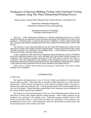
IV. FINITE DIFFERENCE MODEL OF TOOLINGA. Model DescriptionThe model predicts the performance of various conformal cooling channel designs. Thismodel was necessary to develop the final conformal channel design for the 3D Printed inserts. Theinputs to the model include the thermal properties of the plastic (polystyrene), and bronze infiltrated316L stainless steel mold material, mold filling time, cooling time and ejection time in the simulatedinjection molding cycle, the physical dimensions of the cooling channel, mold and plastic meltarea, coolant temperature and plastic melt temperature.A two-dimensional explicit numerical finite difference formulation is used to solve theunsteady heat transfer problem. For simplicity, the mold and plastic melt were modeled as arectangular mold block with a thin rectangular strip of plastic on one face of the block. Filling issimulated by the movement of this plastic "strip" from the gate end to the rib end (point at whichplastic flow melt meets a physical barrier) across the face of the mold block. Fig. 17 depicts aschematic of the model geometry.Plastic MeltGate'\.\ RibFig. 17. Representation of the two-dimensional model.Details of the model formulation will be left for other publications.B. Simulation ResultsFig. 18 shows the results of the finite difference simulation of the heat transfer in the insertswith conformal channels during an injection molding run.464
,.-,U'-'.: . .25Il.l20e':l15Il.le10Il.l \IC\I"d"C\ITime (sec)-----MIDDIE -------- Rill---GATEFig. 18. Finite difference simulation - conformal channels(3D Printed Inserts) - Coolant Temperature 11 CThe results of this finite difference analysis may be compared to the experimental results of thesurface temperature versus time data for the 3D Printed core insert. Fig. 19 depicts one cycle ofthe simulation and one cycle of the experimental mold surface temperature data derived from thegate thermocouple. Fig. 20 depicts the same comparison at the rib thermocouple. The simulationplots have been shifted on the time scale to synchronize the cycle starting time with that of theexperimental data./"'"I'--. ./------ ------- ---------. .I.-
The injection molding process is one of the most widely used methods of manufacturing polymer plastic products. Many parts that are injection molded today have very rigid tolerance requirements. Proper thermal management of metal injection molding tooling is