Transcription
University of NizwaFaculty of Engineering and ArchitectureElectrical and Computer EngineeringELEC207 Linear Integrated CircuitsWeek 1 &2Atef Abu SalimFall 2014/2015
TEXTBOOKRamakant A, Gayakward, “Op-Amps and Linear Integrated Circuits”,PrenticeHall of India, New Delhi, 4th EditionREFERENCES Behzad Razavi, “Design of Analog CMOS IntegratedCircuits”, McGraw Hill, 2001 D. Roy Choudhry, Shail Jain, “Linear Integrated Circuits”,New Age International Pvt. Ltd., 2000
INTRODUCTION We are living in an electronics age. We can say that the evolution of electroniccomponents started from Vaccum tube Diodes through Transistors to IntegratorCircuits.Integrated Circuit (IC)It is a miniature, low cost electronic circuit consisting of active (can amplify)andpassive components (can’t amplify, but attenuate) fabricated together on asinglecrystal of semiconductor (silicon)Linear integrated circuit (Linear IC)It is a solid-state analog device characterized by a theoretically infinite numberofpossible operating states. It operates over a continuous range of input levels.Note Digital IC has a finite number of discrete input and output states
Linear Amplifier When the output of the amplifier is a proportional change of the input, theamplifier is referred as a Linear amplifierFor linear amplifier the input and output relationship can be given asVout(t) A Vin(t)where, A is a constant known as the amplifier gain.Linear amplifierNon-Linear amplifierNote When the output of the amplifier is not a proportional change of theinput, the amplifier is referred as Non-Linear amplifier
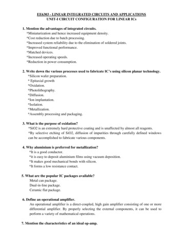
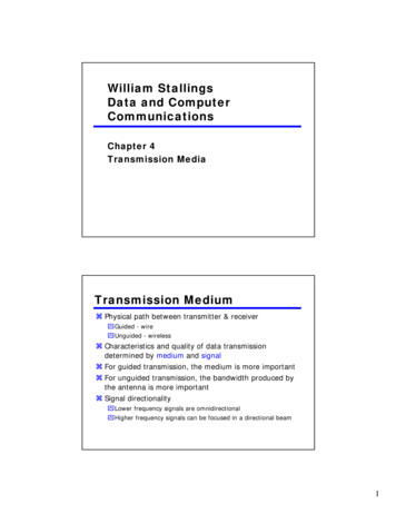
Operational Amplifier Op-amp is a Linear Integrated Circuit used to amplify DC as well as ACsignals and also in signal conditioning, filtering or to perform mathematical operations such as addition, subtraction, integration and differentiation.741 OP-AMP Pin Diagram
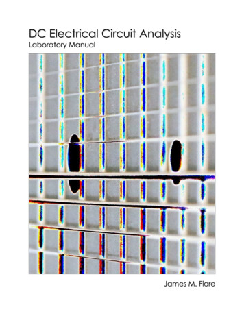
Operational AmplifierOP-AMP Schematic Symbol An AC or DC voltage applied to the non-inverting terminal produces anin-phase (or same polarity) signal at the outputAn AC or DC voltage applied to the inverting terminal produces an 180 out-of-phase (or opposite polarity) signal at the outputThe input-output relationship of the op-amp is Vout A (Vn – Vi)where, A is a constant known as the amplifier gain
CHARACTERISTICS OF AN OP-AMP Input Resistance (Ri): Equivalent resistance that can be measured at eitherthe inverting or non-inverting input terminal with the other terminalconnected to the groundOutput Resistance (Ro): Equivalent resistance that can be measuredbetween the output terminal of the op-amp and the groundVoltage Gain: Ratio of the output voltage and the differential inputvoltagei.e
CHARACTERISTICS OF AN OP-AMP Common-Mode Rejection Ratio (CMRR): Measure of rejection of unwantedsignals common to both the inputs. Ratio of differential gain (Ad) and the commonmode gain (Acm). Ad is very large so CMRR is also large Slew Rate (SR): Maximum rate of change of output voltage per unit of time. Itindicates how rapidly the output of an op-amp can change in response to changes inthe input frequency Gain-Bandwidth Product (GBP)/Closed-loop bandwidth/Unity gainbandwidth: Bandwidth of the op-amp when the voltage gain is 1
CHARACTERISTICS OF AN IDEAL OP-AMP Infinite voltage gain A Infinite input resistance, so that any signal source can drive itand there is no loading of the preceding stage Zero output resistance, so that the output can drive an infinitenumber of other devices and so that it can supply as much currentas necessary to the load Zero output voltage when input voltage is zero Infinite bandwidth so that any frequency signal from 0 to Hzcan be amplified without attenuation. This ensures that the gain ofthe op-amp will be constant over the frequency range from DC(zero frequency) to infinite frequency. So op-amp can amplifyDC as well as AC signals
Cont. Infinite common-mode rejection ratio (CMRR) so that theoutput common mode noise voltage is zero Infinite Slew Rate so that output voltage changes occursimultaneously with input voltage changes
COMPARISON: CHARACTERISTICS OF AN IDEAL OPAMP AND A REAL OP-AMP
OP-AMP Equivalent Circuit The output voltage is directlyproportional to the algebraicdifference between the two inputvoltages.Vo A Vid The op-amp amplifies thedifference between the two inputvoltages and not the input voltageitself. The polarity of the output voltagedepends on the polarity of theVo A Vid A(V difference voltage.– V-) Equivalent circuit is useful inanalyzing the basic operatingA Vo/ Vidprinciples of Op-Amps
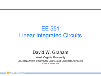
IDEAL VOLTAGE TRANSFER CURVE Graphical representation of the equation Vo A Vid is given by the Idealvoltage transfer curve. Output Voltage is directly proportional to the inputdifference voltage only until it reaches the saturation voltages and there afteroutput remains constant . In other words the output voltage never excess theDC voltage supply of the Op-AmpRepresentation of Op- Amp outputwave formVoltage TransferCurve
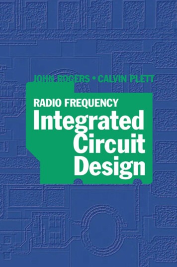
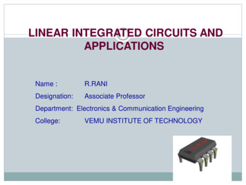
Open loop Frequency Response of anOperational Amplifier From the frequency response curve we can see that the product of the gain against frequency isconstant at any point along the curve. Gain Bandwidth Product Gain x Bandwidth or A x BWA dB 20 log10AFrom the graph gain of the amplifier at 100 KHz,is A 20 dB20 dB 20 log10 Alog10 A 1; A 101 10GBP 100KHz x 10 1 MHzSimilarly, at 1KHz, A 60 dB60 dB 20 log10Alog10A 3; A 103 1000GBP 1KHz x 1000 1 MHzAt 0 dB, it has Unity Gain20 log10A 0; A 100 1GBP 1 MHz x 1 1 MHz
Concept of VIRTUAL SHORT For feedback amplifiers constructed with op-amps, the two op-amp terminalswill always be approximately equal (V V-) This condition in op-amp feedback amplifiers is known as the “virtual short”. This is to avoid saturation as gain of the amplifier is ideally infinitely large. It appears that the two input terminals are shorted together ( Not shorted inreal. It is the feedback that enforces short). If a true short were present, thencurrent could flow from one terminal to the other. However, we know that theinput resistance of an op-amp is ideally Infinite and thus we know that theinput current into an op-amp is zero.Conclusion from Virtual short Concept The voltage difference between Non-inverting and Inverting terminal is zeroV V The current into both Non-inverting and Inverting terminal is zero.I 0 and I- 0
Concept of VIRTUAL SHORTVout A(V1 V2 )(V1 V2 ) VoutV out 0A (V1 V2 ) 0V1 V2 Applying the concept of a virtual short we can simplify the analysis of an op-ampfeedback amplifiers
Inverting Amplifier Input is applied to the inverting terminal of Op-amp Non-inverting terminal is grounded Output voltage is out of phase with the input voltage by 180 degree or is of oppositepolarity V0 - A VinNon-Inverting Amplifier Input is applied to the non-inverting terminal of Op-ampInverting terminal is groundedOutput voltage is in phase with the input voltage or is of same polarityV0 A VinA practical op-amp alone cannot be used as an amplifier with controlled gain and islimited to comparator applications. External resistors are therefore connected to the opamp in a feedback arrangement to set the gain of the amplifier.
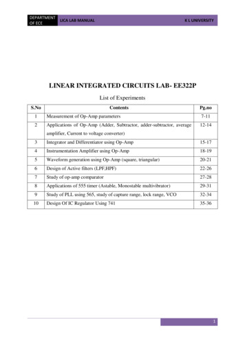
Analysis of INVERTING AMPLIFIER using the concept of VIRTUAL SHORTI in I F I We know,I 0I in I FWe know,Vin V2V Vout 2RinRFV2 V1 0VinV outRinRFGain VoutR FVinRinIf RF Rin,then Vout -Vin
Analysis of NON-INVERTING AMPLIFIER using the concept of VIRTUALSHORTUsing Potential divider Rule:Vin V1 R2 VoutR2 RFVoltage Gain A Vout R2 RFR 1 FVinR2R2
EXAMPLES:1. Find the closed loop gain of the following circuit.2. If Rin is 10kΩ, what value of Rf is required to produce a non-inverting amplifierwith voltage gain of 25?
SOLUTION:1. Find the closed loop gain of the following circuit.Gain RfVout VinRinGain RfRin 100k 1010k 2. If Rin is 10kΩ, what value of Rf is required to produce a non-inverting amplifierwith voltage gain of 25?Gain 1 25 1 RfRinRf10k R f 240k
Ramakant A, Gayakward, “Op-Amps and Linear Integrated Circuits”, Prentice Hall of India, New Delhi, 4th Edition REFERENCES Behzad Razavi, “Design of Analog CMOS Integrated Circuits”, McGraw Hill, 2001 D. Roy Choudhry, Shail Jain, “Linear Integrated Ci