Transcription
Use & Care ManualWith Installation Instructions for the InstallerElectric Residential Heat PumpWater HeatersResidential 50 Gallon - HB SeriesThe purpose of this manual is twofold:one, to provide the installer with the basicdirections and recommendations for theproper installation and adjustment of thewater heater; and two, for the owner–operator, to explain the features, operation,safety precautions, maintenance andtroubleshooting of the water heater. Thismanual also includes a parts list.It is imperative that all persons who areexpected to install, operate or adjust thiswater heater read the instructions carefullyso they may understand how to performthese operations. If you do not understandthese instructions or any terms within it,seek professional advice.Any questions regarding the operation,maintenance, service or warranty of thiswater heater should be directed to theseller from whom it was purchased. Ifadditional information is required, refer tothe section on “If you need service.”DO NOT destroy this manual. Pleaseread carefully and keep in a safe placefor future reference. Recognize this symbol as anindication of Important SafetyInformation!!!Printed in USA 2013 Rheem Manufacturing Co. alifornia Proposition 65CWarning: This product containschemicals known to the State ofCalifornia to cause cancer, birthdefects or other reproductive harm.92-103234-12AP16244 (01/13)
Safety InformationSafety Precautions. . . . . . . . 3-4FOR YOUR RECORDSWrite the model and serial numbers here:#Installation InstructionsLocation. . . . . . . . . . . . . . . . . . 5Water Connections . . . . . . . . . 6Condensate Drain . . . . . . . . . . 6#You can find them on a label on the appliance.Staple sales slip or cancelled check here.Proof of the original purchase date is needed to obtain serviceunder the warranty.Relief Valve. . . . . . . . . . . . . . . 7Electrical Connections. . . . 8-9Pipe Insulation. . . . . . . . . . . 10Installation Checklist. . . . . . . 11READ THIS MANUALOperating InstructionsInside you will find many helpful hints on how to use andmaintain your water heater properly. Just a little preventivecare on your part can save you a great deal of time and moneyover the life of your water heater.Safety Controls . . . . . . . . . . 12Water Temperature . . . . . . . . 12Basic Water Heater Operation . . . . . . . . . . . . . . . . . . . . . .13-14You’ll find many answers to common problems in the BeforeYou Call For Service section. If you review our chart ofTroubleshooting Tips first, you may not need to call for serviceat all.READ THE SAFETY INFORMATIONCare and CleaningDraining. . . . . . . . . . . . . . . . 15Maintenance. . . . . . . . . . . . . 15Your safety and the safety of others are very important.There are many important safety messages in this manualand on your appliance. Always read and obey all safetymessages.!Extended Shut-Down. . . . . 16Troubleshooting TipsBefore You CallFor Service. . . . . . . . . . . . . . 17This is the safety alert symbol. Recognize thissymbol as an indication of Important SafetyInformation!This symbol alerts you to potential hazards thatcan kill or hurt you and others.All safety messages will follow the safety alert symbol andeither the word “DANGER”, “WARNING”, “CAUTION”or “NOTICE”.These words mean: An imminently hazardous situation! DANGERthat will result in death or seriousinjury.Customer ServiceParts List. . . . . . . . . . . . . . . . 20Wiring Diagram. . . . . . . . . . 22If You NeedService. . . . . . . . . . . . . . . . . 242!A potentially hazardous situation thatWARNING !CAUTIONcould result in death or seriousinjury and/or damage to property. A potentially hazardous situation thatmay result in minor or moderateinjury.Attention is called to observe aNOTICE: specified procedure or maintain aspecific condition.
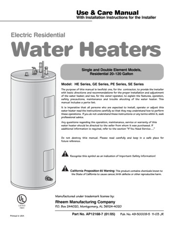
IMPORTANT SAFETY INFORMATION.READ ALL INSTRUCTIONS BEFORE USING.DANGER!WATER TEMPERATURE SETTINGSafety and energy conservation are factors to be considered when selecting the watertemperature setting of water heater. Water temperatures above 125 F can cause severeburns or death from scalding. Be sure to read and follow the warnings outlined on thelabel pictured below. This label is also located on the water heater near the thermistoraccess panel.Time/Temperature Relationship in Scalds!DANGERTemperatureTime To Produce a Serious Burn120 F (49 C)125 F (52 C)130 F (54 C)135 F (57 C)140 F (60 C)145 F (63 C)150 F (65 C)155 F (68 C)More than 5 minutes1½ to 2 minutesAbout 30 secondsAbout 10 secondsLess than 5 secondsLess than 3 secondsAbout 1½ secondsAbout 1 secondTable courtesy of Shriners Burn InstituteThe chart shown above may be used as a guide inHOTdetermining the proper water temperature for yourhome.DANGER: Households with small children,disabled, or elderly persons may require a 120 F orlower thermostat setting to prevent contact with“HOT” water.!BURNWater temperature over 125 F cancause severe burns instantly ordeath from scalds.Children, disabled and elderly areat highest risk of being scalded.See instruction manual beforesetting temperature at waterheater.Feel water before bathing orshowering.Temperature limiting valves areavailable, see manual.NOTICE: Mixing valves are available for reducing pointof use water temperature by mixing hot and cold waterin branch water lines. Contact a licensed plumber or thelocal plumbing authority for further information.The temperature of the water in the heater is regulatedby the water heater interface control. To comply withsafety regulations the temperature was set at 120 Fbefore the water heater was shipped from the factory.The illustration below shows the water temperaturesetting.Refer to the Operating Instructions in this manualfor detailed instructions in how to adjust the watertemperature. ! DANGER: Hotter water increases the potential forHot Water SCALDS.3
IMPORTANT SAFETY INFORMATION.READ ALL INSTRUCTIONS BEFORE USING.WARNING!For your safety, the information in this manual must be followed to minimize the risk offire or explosion, electric shock, or to prevent property damage, personal injury, or loss oflife.Be sure to read and understand the entire Use and Care Manual before attemptingto install or operate this water heater. It may save you time and cost. Pay particularattention to the Safety Instructions. Failure to follow these warnings could result inserious bodily injury or death. Should you have problems understanding the instructionsin this manual, or have any questions, STOP, and get help from a qualified servicetechnician, or the local electric utility.FOR INSTALLATIONS IN THE STATE OF CALIFORNIACalifornia Law requires that residential water heaters must be braced, anchored orstrapped to resist falling or horizontal displacement due to earthquake motions. Forresidential water heaters up to 52-gallon capacity, a brochure with generic earthquakebracing instructions can be obtained from: Office of the State Architect, 1102 Q Street,Suite 5100, Sacramento, CA 95814 or you may call 916-445-8100 or ask a water heaterdealer.However, applicable local codes shall govern installation. For residential water heaters ofa capacity greater than 52 gallons, consult the local building jurisdiction for acceptablebracing procedures.CAUTION: DO NOT “crush” or otherwise impair the removal of the “plastic” front(side) panel.SAFETY PRECAUTIONSHave the installer show you the location of the circuit breaker and how to shut it off ifnecessary. Turn off the circuit breaker if the water heater has been subjected to overheating,fire, flood, physical damage or if the ECO (temperature limiting control) fails to shut off. Read this manual entirely before installingor operating the water heater. Use this appliance only for its intendedpurpose as described in this Use and CareManual. DO NOT attempt to repair or replaceany part of your water heater unless it isspecifically recommended in this manual.All other servicing should be referred to aqualified technician. Be sure your appliance is properly installedin accordance with local codes and theprovided installation instructions.WARNING!Disconnect all power to unit before starting maintenance. Failure to do so can causeelectrical shock resulting in severe personal injury or death.READ AND FOLLOW THIS SAFETY INFORMATIONCAREFULLY.SAVE THESE INSTRUCTIONS4
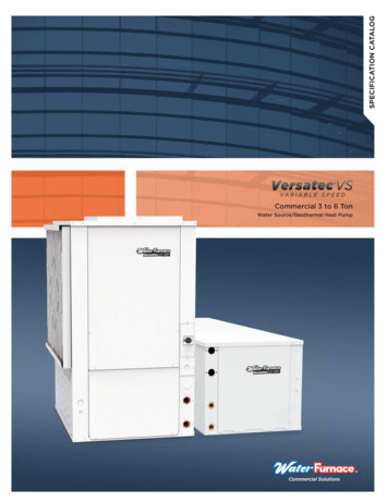
Installing the water heaterThe location chosen for the water heater must take into consideration the following:Local Installation RegulationsThis water heater must be installedin accordance with these instructions,local codes, utility codes, utilitycompany requirements or, in theabsence of local codes, the latestedition of the National ElectricalCode. It is available from some locallibraries or can be purchased from theNational Fire Protection Association,Batterymarch Park, Quincy, MA02269 as booklet ANSI/NFPA 70.Locate the water heater in a clean dryarea as near as practical to the area ofgreatest heated water demand. Longun-insulated hot water lines can wasteenergy and water.to the area adjacent to it or tolower floors of the structure. Wheresuch areas cannot be avoided, itis recommended that a suitablecatch pan, adequately drained, beinstalled under the water heater.Canadian installations should refer toCSA22.1, a copy can be purchasedfrom the Canadian StandardsAssociation, 5050 Spectrum Way,Mississauga,ONT L4W 5N6LocationPlace the water heater in such amanner that the thermistor andelement access panels can be removedto permit inspection and servicing suchas removal of elements or checkingcontrols.The water heater and water linesshould be protected from freezingtemperatures. Do not install the waterheater in outdoor, unprotected areas.Make certain the floor underneaththe water heater is strong enough tosufficiently support the weight ofthe water heater once it is filled withwater.NOTICE: Auxiliary catchpan MUST conform tolocal codes.Catch Pan Kits areavailable from the storewhere the water heater waspurchased, or any waterheater distributor.Catch Pan should notobstruct cold inlet or drainvalve.NOTICE: Installation in a closet orconfined space is not allowed.Heat Pump Water Heater requiresapproximately 1,000 cu. ft(10'x10'x10' Room) of unconditionedindoor ambient air to operate properly.For smaller installations, a louvereddoor is required. The louvered doorshould be maximized to allow airexchanges for optimal performance.A minimum of 2 - 8"x14" louveredregisters fully opened should be usedplacing one at the top of the door andone at bottom.Clearances! CAUTION: The water heatershould not be located in an areawhere leakage of the tank orconnections will result in damageRear2"Top8" Min.BA— Diameter of waterheater plus 2" min.B— Maximum 2″ATo open drain, lineshould be at least 3/4″ IDand pitched for properdrainage.Inspect ShipmentInspect the water heater for possible damage. Check the markings on the ratingplate of the water heater to be certain the power supply corresponds to the waterheater requirements. Rating plate is located on front of water heater.RefrigerantThis heat pump water heater is factory charged with an environmentallyfriendly, non-chlorinated refrigerant, R410A. This refrigerant has zero ozonedepletion potential.5
Installing the water heaterThermal ExpansionDetermine if a check valve exists in theinlet water line. Check with your localwater utility. It may have been installed inthe cold water line as a separate back flowpreventer, or it may be part of a pressurereducing valve, water meter or watersoftener. A check valve located in the coldwater inlet line can cause what is referredto as a “closed water system”. A coldwater inlet line with no check valve or backflow prevention device is referred to as an“open” water system.As water is heated, it expands in volumeand creates an increase in the pressurewithin the water system. This action isreferred to as “thermal expansion”. Inan “open” water system, expanding waterwhich exceeds the capacity of the waterheater flows back into the city main wherethe pressure is easily dissipated.A “closed water system”, however,prevents the expanding water fromflowing back into the main supply line,and the result of “thermal expansion”can create a rapid and dangerous pressureincrease in the water heater and systempiping. This rapid pressure increase canquickly reach the safety setting of therelief valve, causing it to operate duringeach heating cycle. Thermal expansion,and the resulting rapid and repeatedexpansion and contraction of componentsin the water heater and piping system cancause premature failure of the relief valve,and possibly the heater itself. Replacingthe relief valve WILL NOT correct theproblem!The suggested method of controllingthermal expansion is to install an expansiontank in the cold water line between thewater heater and the check valve (referto the illustration on the next page). Theexpansion tank is designed with an aircushion built in that compresses as thesystem pressure increases, thereby relievingthe over pressure condition and eliminatingthe repeated operation of the relief valve.Other methods of controlling thermalexpansion are also available. Contactyour installing contractor, water supplieror plumbing inspector for additionalinformation regarding this subject.Water Supply ConnectionsRefer to the illustration on the nextpage for suggested typical installation. Theinstallation of unions or flexible copperconnectors is recommended on the hotand cold water connections so that thewater heater may be easily disconnectedfor servicing if necessary. The HOT andCOLD water connections are clearlymarked and are 3/4″ NPT on all models.Install a shut-off valve in the cold waterline near the water heater.See page 8 on "To Fill The WaterHeater".NOTICE: Do not apply heat to theHOT or COLD water connections.If sweat connections are used, sweattubing to adapter before fitting adapterto the water connections on heater. Anyheat applied to the water supply fittingswill permanently damage the dip tubeand/or heat traps.Condensate Drains for the Heat PumpConsult local codes or ordinances forspecific requirements. Refer to page 7.6than connection size provided oncondensate drain.IMPORTANT: When making drain fittingconnections to the drain tubing, use a thinlayer of piping tape or silicone and installhand tight. All drain lines must be pitcheddownward away from the unit aminimum of 1/8" per foot of line toensure proper drainage.IMPORTANT: When making drain fittingconnections to the drain tubing, DO NOTovertighten. Overtightening fittings cansplit pipe connections on the drain pan. Do not connect condensate drain lineto a closed or open sewer pipe. DONOT allow condensate to drain intothe water heater drain pan. This unit is equipped with a 3/4"primary condensate connection and a1/2" overflow connection. DO NOT reduce drain line size lessThe drain line should be insulatedwhere necessary to prevent sweatingand damage due to condensateforming on the outside surface of theline.
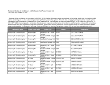
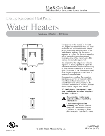
Typical InstallationCeiling8" Minimum clearance above heatpump to allow air circulationHeat pump filterPrimary condensation (3/4")to open drain or outdoorsSecondary condensate tubing(1/2") to open drain or outdoorsElectrical access coverUnionHot water outletto fixturesTemperature and pressurerelief valve and dischargelineShut off valveCold water supplyHeat trap6" MinThermal expansion tank(if required)Union6" Air gapDrain valveA new combination temperature and pressure relief valve, complying with the Standard for Relief Valves andAutomatic Gas Shut-Off Devices for Hot Water Supply Systems, ANSI Z21.22/CSA 4.4, is installed in theopening provided. No valve of any type should be installed between the relief valve and the tank. Local codesshall govern the installation of relief valves.Relief ValveThe BTUH rating of the relief valvemust not be less than the input ratingof the water heater as indicated on therating label located on the front of theheater (1 watt 3.412 BTUH).! WARNING: The pressurerating of the relief valvemust not exceed 150 PSI,the maximum workingpressure of the water heateras marked on the ratingplate.Connect the outlet of the relief valveto a suitable open drain so that thedischarge water cannot contact liveelectrical parts or persons and toeliminate potential water damage.Piping used should be of a typeapproved for hot water distribution.The discharge line must be no smallerthan the outlet of the valve and mustpitch downward from the valve toallow complete drainage (by gravity)of the relief valve and discharge line.The end of the discharge line shouldnot be threaded or concealed andshould be protected from freezing.No valve of any type, restriction orreducer coupling should be installed inthe discharge line.7
Installing the water heater! WARNING: The tank mustbe full of water before heateris turned on. The water heaterwarranty does not coverdamage or failure resultingfrom operation with an emptyor partially empty tank.To Fill the Water HeaterMake certain the drain valve iscompletely closed.allow the air to vent from the waterheater and piping.Open the shut-off valve in the coldwater supply line.A steady flow of water from the hotwater faucet(s) indicates a full waterheater.Open each hot water faucet slowly toEcoNet Communication PortEcoNet communication port is for future integration with home automation,energy management, and demand response systemsEcoNet PortGround ScrewElectrical PowerHookup TerminalsSCALE0.400Electrical Connections! WARNING!Turn off electric power at the fuse box orservice panel before making any electricalconnections.Also, the ground connection must becompleted before making line voltageconnections. Failure to do so can result inelectrical shock, severe personal injury ordeath.8Disconnect all power to unit before startingmaintenance. Failure to do so can causeelectrical shock resulting in severe personalinjury or deathThe unit must be grounded. Failure to do socan cause electrical shock resulting in severepersonal injury or death.
Electrical Connections continued.A separate branch circuit with copperconductors, over current protectivedevice and suitable disconnectingmeans must be provided by a qualifiedelectrician.All wiring must conform to localcodes or latest edition of NationalElectrical Code ANSI/NFPA 70.! CAUTION: The presenceof water in the pipingand water heater doesnot provide sufficientconduction for a ground.Non-metallic piping,dielectric unions, flexibleconnectors etc. can causethe water heater to beelectrically isolated.The water heater is completely wiredto the Electrical Power HookupTerminals inside the jacket at the topfront of the water heater. An openingfor 1/2″ or 3/4″ electrical fitting isprovided for field wiring connections.The voltage requirements and wattageload for the water heater are specifiedon the rating plate on the front of thewater heater.The branch circuit wiring should includeeither: Metallic conduit or metallicsheathed cable approved for useas a grounding conductor andinstalled with fittings approvedfor the purpose. Non-metallic sheathed cable,metallic conduit or metallicsheathed cable not approved foruse as a ground conductor shallinclude a separate conductor forgrounding. It should be attachedto the ground terminals of thewater heater and the electricaldistribution box. 208-230V 1PH 24.0 Max. AMP draw 10 gauge wire Recommended 30 AMP overcurrent protection.Insulation Blankets! WARNING: If localcodes require externalapplication of insulationblanket kits themanufacturer’s instructionsincluded with the kit mustbe carefully followed.Insulation blankets, available tothe general public, for externaluse on electric water heaters arenot necessary. The purpose of aninsulation blanket is to reduce thestandby heat loss encountered withstorage tank heaters. This waterheater meets or exceeds the NationalAppliance Energy Conservation Actstandards with respect to insulationand standby loss requirements makingan ins
proper installation and adjustment of the water heater; and two, for the owner– operator, to explain the features, operation, safety precautions, maintenance and troubleshooting of the water heater. This manual also inclu