Transcription
Radio Frequency Integrated Circuit Design
For a listing of recent titles in the Artech House Microwave Library,turn to the back of this book.
Radio Frequency Integrated Circuit DesignJohn RogersCalvin PlettArtech HouseBoston Londonwww.artechhouse.com
Library of Congress Cataloging-in-Publication DataRogers, John (John W. M.)Radio frequency integrated circuit design / John Rogers, Calvin Plett.p. cm. — (Artech House microwave library)Includes bibliographical references and index.ISBN 1-58053-502-x (alk. paper)1. Radio frequency integrated circuits—Design and construction. 2. Very high speedintegrated circuits. I. Plett, Calvin. II. Title. III. Series.TK7874.78.R64 2003621.3845—dc212003041891British Library Cataloguing in Publication DataRogers, JohnRadio frequency integrated circuit design. — (Artech House microwave library)1. Radio circuits—Design and construction 2. Linear integrated circuits—Design andconstruction 3. Microwave integrated circuits—Design and construction4. Bipolar integrated circuits—Design and construction I. Title II. Plett, Calvin621.3’812ISBN 1-58053-502-xCover design by Igor Valdman 2003 ARTECH HOUSE, INC.685 Canton StreetNorwood, MA 02062All rights reserved. Printed and bound in the United States of America. No part of this bookmay be reproduced or utilized in any form or by any means, electronic or mechanical, includingphotocopying, recording, or by any information storage and retrieval system, without permissionin writing from the publisher.All terms mentioned in this book that are known to be trademarks or service marks have beenappropriately capitalized. Artech House cannot attest to the accuracy of this information. Useof a term in this book should not be regarded as affecting the validity of any trademark or servicemark.International Standard Book Number: 1-58053-502-xLibrary of Congress Catalog Card Number: 200304189110 9 8 7 6 5 4 3 2 1
ContentsForewordxvAcknowledgmentsxix1Introduction to Communications Circuits11.1Introduction11.2Lower Frequency Analog Design and MicrowaveDesign Versus Radio Frequency IntegratedCircuit DesignImpedance Levels for Microwave and LowFrequency Analog DesignUnits for Microwave and Low-Frequency AnalogDesign3Radio Frequency Integrated Circuits Used in aCommunications Transceiver41.4OverviewReferences662Issues in RFIC Design, Noise, Linearity, andFiltering9Introduction91.2.11.2.21.32.1v22
viRadio Frequency Integrated Circuit l NoiseAvailable Noise PowerAvailable Power from AntennaThe Concept of Noise FigureThe Noise Figure of an Amplifier CircuitThe Noise Figure of Components in 32729302.3.6Linearity and Distortion in RF CircuitsPower Series ExpansionThird-Order Intercept PointSecond-Order Intercept PointThe 1-dB Compression PointRelationships Between 1-dB Compression andIP3 PointsBroadband Measures of Linearity31322.4Dynamic Range352.52.5.12.5.2Filtering IssuesImage Signals and Image Reject FilteringBlockers and Blocker FilteringReferencesSelected Bibliography37373941423A Brief Review of Technology433.1Introduction433.2Bipolar Transistor Description433.3 Current Dependence463.4Small-Signal Model473.5Small-Signal Parameters483.63.6.1High-Frequency Effectsf T as a Function of Current49513.73.7.13.7.23.7.3Noise in Bipolar TransistorsThermal Noise in Transistor ComponentsShot Noise1/f Noise53535354
Contentsvii3.8Base Shot Noise Discussion553.9Noise Sources in the Transistor Model553.10Bipolar Transistor Design Considerations563.113.11.13.11.23.11.33.11.4CMOS TransistorsNMOSPMOSCMOS Small-Signal Model Including NoiseCMOS Square Law EquationsReferences5758585860614Impedance Matching634.1Introduction634.2Review of the Smith Chart664.3Impedance Matching694.4Conversions Between Series and Parallel ResistorInductor and Resistor-Capacitor Circuits744.5Tapped Capacitors and Inductors764.6The Concept of Mutual Inductance784.7Matching Using Transformers814.8Tuning a Transformer824.9The Bandwidth of an Impedance TransformationNetwork834.10Quality Factor of an LC Resonator854.11Transmission Lines884.12S, Y, and Z ParametersReferences89935The Use and Design of Passive CircuitElements in IC Technologies955.1Introduction955.2The Technology Back End and Metallization inIC Technologies95
viiiRadio Frequency Integrated Circuit Design5.3Sheet Resistance and the Skin Effect5.4Parasitic Capacitance1005.5Parasitic Inductance1015.6Current Handling in Metal Lines1025.7Poly Resistors and Diffusion Resistors1035.8Metal-Insulator-Metal Capacitors and PolyCapacitors103Applications of On-Chip Spiral Inductors andTransformers1045.10Design of Inductors and Transformers1065.11Some Basic Lumped Models for Inductors1085.12Calculating the Inductance of Spirals1105.13Self-Resonance of Inductors1105.14The Quality Factor of an Inductor1115.15Characterization of an Inductor1155.16Some Notes About the Proper Use of Inductors1175.17Layout of Spiral Inductors1195.18Isolating the Inductor1215.19The Use of Slotted Ground Shields andInductors1225.20Basic Transformer Layouts in IC Technologies1225.21Multilevel Inductors1245.22Characterizing Transformers for Use in ICs1275.95.23On-Chip Transmission Lines5.23.1 Effect of Transmission Line5.23.2 Transmission Line Examples5.24High-Frequency Measurement of On-ChipPassives and Some Common De-EmbeddingTechniques97129130131134
Contentsix5.25Packaging5.25.1 Other Packaging TechniquesReferences1351381396LNA Design1416.16.1.16.1.2Introduction and Basic AmplifiersCommon-Emitter Amplifier (Driver)Simplified Expressions for Widely SeparatedPolesThe Common-Base Amplifier (Cascode)The Common-Collector Amplifier .46.56.6Amplifiers with FeedbackCommon-Emitter with Series Feedback (EmitterDegeneration)The Common-Emitter with Shunt FeedbackNoise in AmplifiersInput-Referred Noise Model of the BipolarTransistorNoise Figure of the Common-Emitter AmplifierInput Matching of LNAs for Low NoiseRelationship Between Noise Figure and BiasCurrentEffect of the Cascode on Noise FigureNoise in the Common-Collector AmplifierLinearity in AmplifiersExponential Nonlinearity in the BipolarTransistorNonlinearity in the Output Impedance of theBipolar TransistorHigh-Frequency Nonlinearity in the BipolarTransistorLinearity in Common-Collector 71172172180182182Differential Pair (Emitter-Coupled Pair) andOther Differential Amplifiers183Low-Voltage Topologies for LNAs and the Useof On-Chip Transformers184
xRadio Frequency Integrated Circuit Design6.76.7.1DC Bias NetworksTemperature Effects1871896.8Broadband LNA Design ExampleReferencesSelected .2Mixing with Nonlinearity1977.3Basic Mixer Operation1987.4Controlled Transconductance Mixer1987.5Double-Balanced Mixer2007.67.6.17.6.27.6.3Mixer with Switching of Upper QuadWhy LO Switching?Picking the LO LevelAnalysis of Switching Modulator2022032042057.7Mixer Noise2067.87.8.17.8.2LinearityDesired NonlinearityUndesired Nonlinearity2152152157.9Improving Isolation2177.107.10.17.10.27.10.3Image Reject and Single-Sideband MixerAlternative Single-Sideband MixersGenerating 90 Phase ShiftImage Rejection with Amplitude and ative Mixer DesignsThe Moore MixerMixers with Transformer InputMixer with Simultaneous Noise and PowerMatch7.11.4 Mixers with Coupling Capacitors224227228228229230
General Design CommentsSizing TransistorsIncreasing GainIncreasing IP3Improving Noise FigureEffect of Bond Pads and the PackageMatching, Bias Resistors, and Gain2312322322322332332347.13CMOS MixersReferencesSelected Bibliography2422442448Voltage-Controlled Oscillators2458.1Introduction2458.2Specification of Oscillator Properties2458.3The LC Resonator2478.4Adding Negative Resistance Through Feedbackto the Resonator248Popular Implementations of Feedback to theResonator250Configuration of the Amplifier (Colpitts or G m )2518.78.7.18.7.28.7.38.7.4Analysis of an Oscillator as a Feedback SystemOscillator Closed-Loop AnalysisCapacitor Ratios with Colpitts OscillatorsOscillator Open-Loop AnalysisSimplified Loop Gain gativeNegativeNegativeCircuitsNegative8.9Comments on Oscillator Analysis2688.10Basic Differential Oscillator Topologies2708.58.6Resistance Generated by the AmplifierResistance of Colpitts OscillatorResistance for Series and ParallelResistance Analysis of G m Oscillator263265
xiiRadio Frequency Integrated Circuit Design8.11A Modified Common-Collector ColpittsOscillator with Buffering2708.12Several Refinements to the G m Topology2708.13The Effect of Parasitics on the Frequency ofOscillation2748.14Large-Signal Nonlinearity in the Transistor2758.15Bias Shifting During Startup2778.16Oscillator Amplitude2778.17Phase Noise8.17.1 Linear or Additive Phase Noise and Leeson’sFormula8.17.2 Some Additional Notes About Low-FrequencyNoise8.17.3 Nonlinear Noise2832832912928.18Making the Oscillator Tunable2958.19VCO Automatic-Amplitude Control Circuits3028.20Other OscillatorsReferencesSelected Bibliography3133163179High-Frequency Filter Circuits3199.1Introduction3199.2Second-Order Filters3209.39.3.19.3.29.3.3Integrated RF FiltersA Simple Bandpass LC FilterA Simple Bandstop FilterAn Alternative Bandstop Filter3213213223239.49.4.1Achieving Filters with Higher QDifferential Bandpass LNA with Q -Tuned LoadResonatorA Bandstop Filter with Colpitts-Style NegativeResistanceBandstop Filter with Transformer-Coupled G mNegative Resistance3279.4.29.4.3327329331
Contentsxiii9.5Some Simple Image Rejection Formulas3339.6Linearity of the Negative Resistance Circuits3369.7Noise Added Due to the Filter Circuitry3379.8Automatic Q Tuning3399.9Frequency Tuning3429.10Higher-Order FiltersReferencesSelected Bibliography34334634710Power Amplifiers34910.1Introduction34910.2Power Capability35010.3Efficiency Calculations35010.4Matching Considerations10.4.1 Matching to S 22* Versus Matching to opt35135210.510.5.110.5.210.5.3Class A, B, and C AmplifiersClass A, B, and C AnalysisClass B Push-Pull ArrangementsModels for Transconductance35335636236310.6Class D ss E AmplifiersAnalysis of Class E AmplifierClass E EquationsClass E Equations for Finite Output QSaturation Voltage and ResistanceTransition Time36837037137237337310.8Class F Amplifiers10.8.1 Variation on Class F: Second-Harmonic Peaking10.8.2 Variation on Class F: Quarter-WaveTransmission Line37537937910.9Class G and H Amplifiers38110.10Class S Amplifiers383
xivRadio Frequency Integrated Circuit Design10.11Summary of Amplifier Classes for RF IntegratedCircuits38410.12AC Load Line38510.13Matching to Achieve Desired Power38510.14Transistor Saturation38810.15Current Limits38810.16Current Limits in Integrated Inductors39010.17Power Combining39010.18Thermal Runaway—Ballasting39210.19Breakdown 1.310.21.410.21.510.21.6Effects and Implications of NonlinearityCross ModulationAM-to-PM ConversionSpectral RegrowthLinearization 10.22CMOS Power Amplifier ExampleReferences398399About the Authors401Index403
ForewordI enjoyed reading this book for a number of reasons. One reason is that itaddresses high-speed analog design in the context of microwave issues. This isan advanced-level book, which should follow courses in basic circuits andtransmission lines. Most analog integrated circuit designers in the past workedon applications at low enough frequency that microwave issues did not arise.As a consequence, they were adept at lumped parameter circuits and often notcomfortable with circuits where waves travel in space. However, in order todesign radio frequency (RF) communications integrated circuits (IC) in thegigahertz range, one must deal with transmission lines at chip interfaces andwhere interconnections on chip are far apart. Also, impedance matching isaddressed, which is a topic that arises most often in microwave circuits. In mycareer, there has been a gap in comprehension between analog low-frequencydesigners and microwave designers. Often, similar issues were dealt with in twodifferent languages. Although this book is more firmly based in lumped-elementanalog circuit design, it is nice to see that microwave knowledge is brought inwhere necessary.Too many analog circuit books in the past have concentrated first on thecircuit side rather than on basic theory behind their application in communications. The circuits usually used have evolved through experience, without asatisfying intellectual theme in describing them. Why a given circuit works bestcan be subtle, and often these circuits are chosen only through experience. Forthis reason, I am happy that the book begins first with topics that require anintellectual approach—noise, linearity and filtering, and technology issues. Iam particularly happy with how linearity is introduced (power series). In therest of the book it is then shown, with specific circuits and numerical examples,how linearity and noise issues arise.xv
xviRadio Frequency Integrated Circuit DesignIn the latter part of the book, the RF circuits analyzed are ones thatexperience has shown to be good ones. Concentration is on bipolar circuits,not metal oxide semiconductors (MOS). Bipolar still has many advantages athigh frequency. The depth with which design issues are addressed would notbe possible if similar MOS coverage was attempted. However, there might beroom for a similar book, which concentrates on MOS.In this book there is a lot of detailed academic exploration of someimportant high-frequency RF bipolar ICs. One might ask if this is importantin design for application, and the answer is yes. To understand why, one mustappreciate the central role of analog circuit simulators in the design of suchcircuits. At the beginning of my career (around 1955–1960) discrete circuitswere large enough that good circuit topologies could be picked out by breadboarding with the actual parts themselves. This worked fairly well with someanalog circuits at audio frequencies, but failed completely in the progression tointegrated circuits.In high-speed IC design nowadays, the computer-based circuit simulatoris crucial. Such simulation is important at four levels. The first level is the useof simplified models of the circuit elements (idealized transistors, capacitors,and inductors). The use of such models allows one to pick out good topologiesand eliminate bad ones. This is not done well with just paper analysis becauseit will miss key factors, such as the complexities of the transistor, particularlynonlinearity and bias and signal interaction effects. Exploration of topologieswith the aid of a circuit simulator is necessary. The simulator is useful for quickiteration of proposed circuits, with simplified models to show any fundamentalproblems with a proposed circuit. This brings out the influence of modelparameters on circuit performance. This first level of simulation may be avoidedif the best topology, known through experience, is picked at the start.The second level of simulation is where the models are representative ofthe type of fabrication technology being used. However, we do not yet usespecific numbers from the specific fabrication process and make an educatedapproximation to likely parasitic capacitances. Simulation at this level can beused to home in on good values for circuit parameters for a given topologybefore the final fabrication process is available. Before the simulation begins,detailed preliminary analysis at the level of this book is possible, and manyparameters can be wisely chosen before simulation begins, greatly shorteningthe design process and the required number of iterations. Thus, the analysisshould focus on topics that arise, given a typical fabrication process. I believethis has been done well here, and the authors, through scholarly work and realdesign experience, have chosen key circuits and topics.The third level of design is where a link with a proprietary industrialprocess has been made, and good simulator models are supplied for the process.The circuit is laid out in the proprietary process and simulation is done, including
Forewordxviiestimates of parasitic capacitances from interconnections and detailed modelsof the elements used.The incorporation of the proprietary models in the simulation of thecircuit is necessary because when the IC is laid out in the actual process,fabrication of the result must be successful to the highest possible degree. Thisis because fabrication and testing is extremely expensive, and any failure canresult in the necessity to change the design, requiring further fabrication andretesting, causing delay in getting the product to market.The fourth design level is the comparison of the circuit behavior predictedfrom simulation with that of measurements of the actual circuit. Discrepanciesmust be explained. These may be from design errors or from inadequacies inthe models, which are uncovered by the experimental result. These modelinadequacies, when corrected, may result in further simulation, which causesthe circuit design and layout to be refined with further fabrication.This discussion has served to bring attention to the central role thatcomputer simulation has in the design of integrated RF circuits, and the accompanying importance of circuit analysis such as presented in this book. Such detailedanalysis may save money by facilitating the early success of applications. Thisbook can be beneficial to designers, or by those less focused on specific design,for recognizing key constraints in the area, with faith justified, I believe, thatthe book is a correct picture of the reality of high-speed RF communicationscircuit design.Miles A. CopelandFellow IEEEProfessor EmeritusCarleton University Department of ElectronicsOttawa, Ontario, CanadaApril 2003
AcknowledgmentsThis book has evolved out of a number of documents including technical papers,course notes, and various theses. We decided that we would organize some ofthe research we and many others had been doing and turn it into a manuscriptthat would serve as a comprehensive text for engineers interested in learningabout radio frequency integrated circuits (RFIC). We have focused mainly onbipolar technology in the text, but since many techniques in RFICs are independent of technology, we hope that designers working with other technologieswill also find much of the text useful. We have tried very hard to identify andexterminate bugs and errors from the text. Undoubtedly there are still manyremaining, so we ask you, the reader, for your understanding. Please feel freeto contact us with your comments. We hope that these pages add to yourunderstanding of the subject.Nobody undertakes a project like this without support on a number oflevels, and there are many people that we need to thank. Professors MilesCopeland and Garry Tarr provided technical guidance and editing. We wouldlike to thank David Moore for his input and consultation on many aspects ofRFIC design. David, we have tried to add some of your wisdom to these pages.Thanks also go to Dave Rahn and Steve Kovacic, who have both contributedto our research efforts in a variety of ways. We would like to thank Sandi Plettwho tirelessly edited chapters, provided formatting, and helped beat the wordprocessor into submission. She did more than anybody except the authors tomake this project happen. We would also like to thank a number of graduatestudents, alumni, and colleagues who have helped us with our understandingof RFICs over the years. This list includes but is not limited to Neric Fong,xix
xxRadio Frequency Integrated Circuit DesignBill Toole, José Macedo, Sundus Kubba, Leonard Dauphinee, Rony Amaya,John J. Nisbet, Sorin Voinegescu, John Long, Tom Smy, Walt Bax, BrianRobar, Richard Griffith, Hugues Lafontaine, Ash Swaminathan, Jugnu Ojha,George Khoury, Mark Cloutier, John Peirce, Bill Bereza, and Martin Snelgrove.
1Introduction to CommunicationsCircuits1.1 IntroductionRadio frequency integrated circuit (RFIC) design is an exciting area for researchor product development. Technologies are constantly being improved, and asthey are, circuits formerly implemented as discrete solutions can now be integrated onto a single chip. In addition to widely used applications such as cordlessphones and cell phones, new applications continue to emerge. Examples of newproducts requiring RFICs are wireless local-area networks (WLAN), keyless entryfor cars, wireless toll collection, Global Positioning System (GPS) navigation,remote tags, asset tracking, remote sensing, and tuners in cable modems. Thus,the market is expanding, and with each new application there are uniquechallenges for the designers to overcome. As a result, the field of RFIC designshould have an abundance of products to keep designers entertained for yearsto come.This huge increase in interest in radio frequency (RF) communications hasresulted in an effort to provide components and complete systems on an integratedcircuit (IC). In academia, there has been much research aimed at putting acomplete radio on one chip. Since complementary metal oxide semiconductor(CMOS) is required for the digital signal processing (DSP) in the back end,much of this effort has been devoted to designing radios using CMOS technologies [1–3]. However, bipolar design continues to be the industry standardbecause it is a more developed technology and, in many cases, is better modeled.Major research is being done in this area as well. CMOS traditionally had theadvantage of lower production cost, but as technology dimensions become1
2Radio Frequency Integrated Circuit Designsmaller, this is becoming less true. Which will win? Who is to say? Ultimately,both will probably be replaced by radically different technologies. In any case,as long as people want to communicate, engineers will still be building radios.In this book we will focus on bipolar RF circuits, although CMOS circuits willalso be discussed. Contrary to popular belief, most of the design concepts inRFIC design are applicable regardless of what technology is used to implementthem.The objective of a radio is to transmit or receive a signal between sourceand destination with acceptable quality and without incurring a high cost. Fromthe user’s point of view, quality can be perceived as information being passedfrom source to destination without the addition of noticeable noise or distortion.From a more technical point of view, quality is often measured in terms of biterror rate, and acceptable quality might be to experience less than one error inevery million bits. Cost can be seen as the price of the communications equipmentor the need to replace or recharge batteries. Low cost implies simple circuits tominimize circuit area, but also low power dissipation to maximize battery life.1.2 Lower Frequency Analog Design and Microwave DesignVersus Radio Frequency Integrated Circuit DesignRFIC design has borrowed from both analog design techniques, used at lowerfrequencies [4, 5], and high-frequency design techniques, making use of microwave theory [6, 7]. The most fundamental difference between low-frequencyanalog and microwave design is that in microwave design, transmission lineconcepts are important, while in low-frequency analog design, they are not.This will have implications for the choice of impedance levels, as well as howsignal size, noise, and distortion are described.On-chip dimensions are small, so even at RF frequencies (0.1–5 GHz),transistors and other devices may not need to be connected by transmissionlines (i.e., the lengths of the interconnects may not be a significant fraction ofa wavelength). However, at the chip boundaries, or when traversing a significantfraction of a wavelength on chip, transmission line theory becomes veryimportant. Thus, on chip we can usually make use of analog design concepts,although, in practice, microwave design concepts are often used. At the chipinterfaces with the outside world, we must treat it like a microwave circuit.1.2.1 Impedance Levels for Microwave and Low-Frequency AnalogDesignIn low-frequency analog design, input impedance is usually very high (ideallyinfinity), while output impedance is low (ideally zero). For example, an operational amplifier can be used as a buffer because its high input impedance doesnot affect the circuit to which it is connected, and its low output impedance
Introduction to Communications Circuits3can drive a measurement device efficiently. The freedom to choose arbitraryimpedance levels provides advantages in that circuits can drive or be driven byan impedance that best suits them. On the other hand, if circuits are connectedusing transmission lines, then these circuits are usually designed to have aninput and output impedance that match the characteristic impedance of thetransmission line.1.2.2 Units for Microwave and Low-Frequency Analog DesignSignal, noise, and distortion levels are also described differently in low frequencyanalog versus microwave design. In microwave circuits, power is usually usedto describe signals, noise, or distortion with the typical unit of measure beingdecibels above 1 milliwatt (dBm). However, in analog circuits, since infinite orzero impedance is allowed, power levels are meaningless, so voltages and currentare usually chosen to describe the signal levels. Voltage and current are expressedas peak, peak-to-peak, or root-mean-square (rms). Power in dBm, P dBm , can berelated to the power in watts, Pwatt , as shown in (1.1) and Table 1.1, wherevoltages are assumed to be across 50 .P dBm 10 log 10冉 冊Pwatt1 mW(1.1)Assuming a sinusoidal voltage waveform, Pwatt is given byPwatt2v rms R(1.2)where R is the resistance the voltage is developed across. Note also that v rmscan be related to the peak voltage v pp byTable 1.1Power Relationshipsv ppv rmsP watt (50 )P dBm (50 )1 nV1 V1 mV10 mV100 mV632.4 mV1V10V0.3536 nV0.3536 V353.6 V3.536 mV35.36 mV223.6 mV353.6 mV3.536V2.5 10 212.5 10 152.5 nW250 nW25 W1 mW2.5 mW250 mW 176 116 56 36 160 4 24
4Radio Frequency Integrated Circuit Designv rms v pp(1.3)2 2Similarly, noise in analog signals is often defined in terms of volts oramperes, while in microwave it will be in terms of dBm. Noise is usuallyrepresented as noise density per hertz of bandwidth. In analog circuits, noiseis specified as squared volts per hertz, or volts per square root of hertz. Inmicrowave circuits, the usual measure of noise is dBm/Hz or noise figure, whichis defined as the reduction in signal-to-noise ratio caused by the addition ofthe noise.In both analog and microwave circuits, an effect of nonlinearity is theappearance of harmonic distortion or intermodulation distortion, often at newfrequencies. In low-frequency analog circuits, this is often described by the ratioof the distortion components compared to the fundamental components. Inmicrowave circuits, the tendency is to describe distortion by gain compression(power level where the gain is reduced due to nonlinearity) or third-orderintercept point (IP3).Noise and linearity are discussed in detail in Chapter 2. A summary oflow-frequency analog and microwave design is shown in Table 1.2.1.3 Radio Frequency Integrated Circuits Used in aCommunications TransceiverA typical block diagram of most of the major circuit blocks that make up atypical superheterodyne communications transceiver is shown in Figure 1.1.Many aspects of this transceiver are common to all transceivers.Table 1.2Comparison of Analog and Microwave DesignParameterAnalog Design(most often used on chip)Microwave Design(most often used at chipboundaries and pins)ImpedanceZ in Z out 0Voltage, current, often peakor peak-to-peaknV/ HzHarmonic distortion,intermodulation, clippingZ in 50 Z out 50 Power, often dBmSignalsNoiseNonlinearityNoise factor F, noise figure NFThird-order intercept point IP31-dB compression
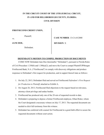
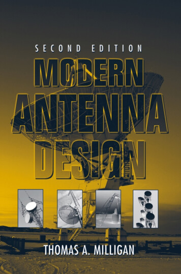
Introduction to Communications Circuits5Figure 1.1 Typical transceiver block diagram.This transceiver has a transmit side (Tx) and a receive side (Rx), whichare connected to the antenna through a duplexer that can be realized as a switchor a filter, depending on the communications standard being followed. Theinput preselection filter takes the broad spectrum of signals coming from theantenna and removes the signals not in the band of interest. This may berequired to prevent overloading of the low-noise amplifier (LNA) by out-ofband signals. The LNA amplifies the input signal without adding much noise.The input signal can be very weak, so the first thing to do is strengthen thesignal without corrupting it. As a result, noise added in later stages will be ofless importance. The image filter that follows the LNA removes out-of-bandsignals and noise (which will be discussed in detail in Chapter 2) before thesignal enters the mixer. The mixer translates the input RF signal down to theintermediate frequency, since filtering, as well as circuit design, becomes mucheasier at lower frequencies for a multitude of reasons. The other input to themixer is the local oscillator (LO) signal provided by a voltage-controlled oscillatorinside a frequency synthesizer. The desired output of the mixer will be thedifference between the LO frequency and the RF frequency.At the input of the radio there may be many different channels or frequencybands. The LO frequency is adjusted so that the desired RF channel or frequencyband is mixed down to the same intermediate frequency (IF) in all cases. TheIF stage then provides channel filtering at this one frequency to remove theunwanted channels. The IF stage provide
Linear integrated circuits—Design and construction 3. Microwave integrated circuits—Design and construction 4. Bipolar integrated circuits—Design and construction I. Title II. Plett, Calvin