Transcription
1LINEAR INTEGRATEDCIRCUITS ANDAPPLICATIONSName :R.RANIDesignation:Associate ProfessorDepartment: Electronics & Communication EngineeringCollege:VEMU INSTITUTE OF TECHNOLOGY
COURSE OUTCOMESExplain the characteristics of differential & operational amplifiersC314.1Analyze Negative Feedback and its frequency response of Op-amp.C314.2C314.3C314.4Acquire the knowledge to design linear applications of op amps and also activefiltersDesign circuits using Op- amp to generate sinusoidal & non sinusoidal waveforms and explain the operations of 555timer and PLL.Analyze data converters (ADC and DAC) Circuits using Op amps.C314.5
JAWAHARLAL NEHRU TECHNOLOGICAL UNIVERSITYANANTAPURB. Tech III-I Sem. (ECE)LTPC310315A04503 LINEAR INTEGRATED CIRCUITS ANDAPPLICATIONS Course Objectives:Design of OPAMPS, Classification of OPAMPs.To study and design various linear applications of OPAMPs.To study and design various non linear applications of OPAMPs Course Outcomes: Understand the basic building blocks of linear integrated circuits and itscharacteristics. Analyze the linear, non-linear and specialized applications of operationalamplifiers. Understand the theory of ADC and DAC. Realize the importance of Operational Amplifier.
UNIT – IDifferential Amplifiers: Differential amplifierconfigurations, Balanced and unbalanced output differentialamplifiers, current mirror, level Translator.Operational amplifiers: Introduction, Block diagram,Ideal op-amp, Equivalent Circuit Voltage Transfer curve,open loop op-amp configurations. Introduction to dual OPAMP TL082 as a general purpose JFET-input OperationalAmplifier. UNIT-IIIntroduction, feedback configurations, voltage seriesfeedback, voltage shunt feedbackand differential amplifiers, properties of Practical op-amp.Frequency response: Introduction, compensatingnetworks, frequency response of internally compensated opamps and non compensated op-amps, High frequency opampequivalent circuit, open loop gain Vs frequency, closed loopfrequency response, circuit stability, slew rate.
UNIT-IIIDC and AC amplifiers, peaking amplifier, summing, scaling andaveraging amplifiers, instrumentation amplifier, voltage tocurrent converter, current to voltage converter, integrator,differentiator, active filters, First, Second and Third orderButterworth filter and its frequency response, Tow-Thomasbiquad filter. UNIT-IVOscillators, Phase shift and wein bridge oscillators, Square,triangular and saw tooth wave generators, Comparators, zerocrossing detector, Schmitt trigger, characteristics and limitations. Specialized applications: 555 timer IC (monostable&astableoperation) & its applications, PLL, operating principles, onolithicPLL, applications, analog multiplier and phase detection, Widebandwidth precision analog multiplier MPY634 and its applications.
UNIT VAnalog and Digital Data Conversions, D/A converter –specifications – weighted resistor type, R-2R Laddertype, Voltage Mode and Current-Mode R -2R Laddertypes - switches for D/A converters, high speed sampleand-hold circuits, A/D Converters – specifications –Flash type – Successive Approximation type – SingleSlope type – Dual Slope type – A/D Converter usingVoltage-to-Time Conversion –Over-sampling A/DConverters.
7
INTEGRATED CIRCUITSAn integrated circuit (IC) is a miniature ,low costelectronic circuit consisting of active and passivecomponents fabricated together on a single crystal ofsilicon. The active components are transistors and diodesand passive components are resistors and capacitors.8
1.2.3.4.5.6.7.Miniaturization and hence increased equipmentdensity.Cost reduction due to batch processing.Increased system reliability due to the eliminationof soldered joints.Improved functional performance.Matched devices.Increased operating speeds.Reduction in power consumption9
Classification Digital ICs Linear ICsIntegrated circuitsHybrid circuitsMonolithic circuitsBipolarPn junctionisolationUni polarDielectricisolationMOSFETJFET10
Chip size and Complexity Invention of Transistor (Ge) Development of Silicon- 1947- 1955-1959 Silicon Planar Technology First ICs, SSI (3- 30gates/chip)- 1959- 1960 MSI ( 30-300 gates/chip)- 1965-1970 LSI ( 300-3000 gates/chip)-1970-1975 VLSI (More than 3k gates/chip) - 1975 ULSI (more than one million active devices are integrated on single chip)11
OPERATION AMPLIFIERAn operational amplifier is a direct coupled high gainamplifier consisting of one or more differential amplifiers,followed by a level translator and an output stage.It is a versatile device that can be used to amplifyac as well as dc input signals & designed for computingmathematical functions such as addition, subtraction,multiplication, integration & differentiation12
IC packages available132.Metal can package.Dual-in-line package.3.Ceramic flat package.1.
Block diagram of op amp14
DIFFERENTIAL AMPLIFIER:Differential amplifier is a basic building block of an op-amp.The function of a differentialamplifier is to amplify the difference between two inputsignals.
The four differential amplifier configurations are following:1. Dual input, balanced output differential amplifier.2. Dual input, unbalanced output differential amplifier.3. Single input balanced output differential amplifier.4. Single input unbalanced output differential amplifier
DUAL INPUT , BALANCED OUTPUT DIFFERENTIALAMPLIFIER :The circuit is shown in fig 1, v1 and v2 are the two inputs,applied to the bases of Q1 and Q2transistors. The output voltage is measured between the twocollectors C1 and C2 , which are atsame dc potentials.DC ANALYSIS:
VC VCC – Ic Rcand VCE VC - VE VCC - IC RC VBEVCE VCC VBE - ICRC
AC ANALYSISDIFFRENTIAL I/P RESISTANCE
OUT PUT RESISTANCE:R0 1 R02 RCSINGLE I/P UNBALANCED O/P AMP
AC ANALYSISVOLTAGE GAINDIFFRENTIAL I/P RESISTANCEOUT PUT RESISTANCE:R0 1 R02 RC
Terminals on an Op AmpPositive power supply(Positive rail)Non-invertingInput terminalOutput terminalInverting inputterminalNegative power supply(Negative rail)
1.2 Ideal Op-Amp25Vout AvVin Infinite Open-Loop Gain Open-LoopGain, A is the gain of the op-ampwithout feedback. In the ideal op-amp, A is infinite In real op-amp, A is 20k to 200k
Ideal Voltage transfer curve VsatAOL -Vd0 Vd Vsat Vcc-Vsat26
Why op-amp is generally not used in open loopmode?As open loop gain of op-amp is very large, very small inputvoltage drives the op-amp voltage to the saturation level. Thusin open loop configuration, the output is at its positivesaturation voltage ( Vsat ) or negative saturation voltage (-Vsat )depending on which input V1 or V2 is more than the other. Fora.c. input voltages, output may switch between positive andnegative saturation voltages
This indicates the inability of op-amp to work as a linear small signalamplifier in the open loop mode. Hence the op-amp in open loopconfiguration is not used for the linear applications
Operational Amplifier Model An operational amplifier circuit is designed so that1) Vout Av (V1-V2) (Av is a very large gain)2) Input resistance (Rin) is very large3) Output resistance (Rout) is very lowV1RoutRinV2 -Av(V1- V2)Vout
Op Amp Equivalent Circuitvd v2 – v1v2A is the open-loop voltage gainv1Voltage controlledvoltage source
The Operational Amplifier VSInvertingi(-)vidNoninvertingi( )RORiOutputAvO AdVid -VS i( ), i(-) : Currents into the amplifier on the inverting and non-inverting linesrespectively vid : The input voltage from inverting to non-inverting inputs VS , -VS : DC source voltages, usually 15V and –15V Ri : The input resistance, ideally infinity A : The gain of the amplifier. Ideally very high, in the 1x10 10 range. RO: The output resistance, ideally zero vO: The output voltage; vO AOLvid where AOL is the open-loop voltage gain
The Ideal Operational Amplifier Open loop voltage gainAOL Input ImpedanceRi Output ImpedanceRo 0 BandwidthBW Zero offset (Vo 0 when V1 V2 0)Vios 0 CMRRρ Slew rateS PSRR 0 No effect of temperature Power supply rejection ratio
An IDEAL OP AMPAn ideal op amp has the following characteristics:1.Infinite open-loop voltage gain, AV .2.Infinite input resistance, Ri .3.Zero output resistance, Ro 0.4.Infinite CMRR, ρ 5.The output voltage Vo 0; when Vd V2-V1 06.Change of output with respect to input, slew rate 7.Change in out put voltage with Temp., Vo/ Vi 0
Ideal Op-amp1. An ideal op-amp draws no current at both the inputterminals I.e. I1 I2 0. Thus its input impedance isinfinite. Any source can drive it and there is no loading onthe driver stage2. The gain of an ideal op-amp is infinite, hence the differentialinput Vd V1 – V2 is essentially zero for the finite outputvoltage Vo3. The output voltage Vo is independent of the current drawnfrom the output terminals. Thus its output impedance iszero and hence output can drive an infinite number of othercircuits
Example #3: Closed Loop Gainwith Real Op Ampifisi1v1ii2v2
IC Package types Metal can Package Dual-in-line Flat Pack
Metal can Packages The metal sealing plane is at the bottom over which the chip isbounded It is also called transistor pack
Doul-in-line Package The chip is mounted inside a plastic or ceramic case The 8 pin Dip is called MiniDIP and also available with 12,14, 16, 20pins
Flat pack The chip is enclosed in a rectangular ceramic case
PackagesThe metal can (TO)The Flat PackagePackageThe Dual-in-Line (DIP)Package
Temperature Ranges1. Military temperature range : -55o C to 125o C (-55o C to 85o C)2. Industrial temperature range: -20o C to 85o C (-40o C to 85o C )3. Commercial temperature range: 0o C to 70o C (0o C to 75o C )
Manufacturer’s Designation for Linear ICs Fairchild- µA, µAF National Semiconductor- LM,LH,LF,TBA Motorola- MC,MFC RCA- CA,CD Texas Instruments- SN Signetics- N/S,NE/SE Burr- Brown- BB
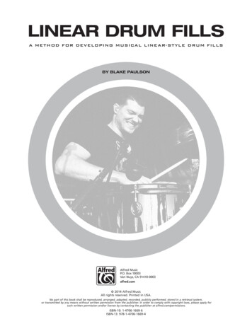
The 8pin DIP package of IC 741
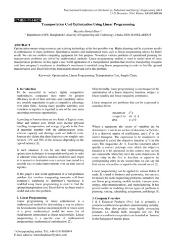
TL 082 PIN CONFIGURATION
45
46Def: The “Integrated Circuit “ or IC is a miniature, lowcost electronic circuit consisting of active and passivecomponents that are irreparably joined together on asingle crystal chip of silicon.
47
48
49
50
Selection of IC PackageTypeCriteriaMetal canpackage1.DIP1.2.2.3.Flat pack1.2.3.Heat dissipation is importantFor high power applications like poweramplifiers, voltage regulators etc.For experimental or bread boardingpurposes as easy to mountIf bending or soldering of the leads is notrequiredSuitable for printed circuit boards as leadspacing is moreMore reliability is requiredLight in weightSuited for airborne applications51
Inverting Op-Amp52VOUT VINRfR1
Non-Inverting Amplifier53 R VOUT VIN 1 1 R2
Voltage follower54
Characteristics and performance parametersof Op-amp55 Input offset Voltage Input offset current Input bias current Differential input resistance Input capacitance Open loop voltage gain CMRR Output voltage swing
Basic Information of an Op-amp56Power supply connection:The power supply voltage may range from about 5V to 22V.The common terminal of the V and V- sources isconnected to a reference point or ground.
Differential AmplifierV0 Ad (V1 – V2 )Ad 20 log10 (Ad ) in dBVc (V1 V2 )2CMRR ρ Ad Ac57
1. Input Offset Voltage58INPUT OFFSET VOLTAGEThe differential voltage that must be applied betweenthe two input terminals of an op-amp, to make theoutput voltage zero.It is denoted as ViosFor op-amp 741C the input offset voltage is6mV
592. Input offset currentThe algebraic difference between the currents flowing intothe two input terminals of the op-ampIt is denoted as Iios Ib1 – Ib2 For op-amp 741C the input offset current is 200nA
603. Input bias currentThe average value of the two currents flowing intothe op-amp input terminalsIt is expressed mathematically asI b1 I b 22For 741C the maximum value of Ib is 500nA
614. Differential Input ResistanceIt is the equivalent resistance measured at either theinverting or non-inverting input terminal with theother input terminal groundedIt is denoted as RiFor 741C it is of the order of 2MΩ
7. CMRRIt is the ratio of differential voltage gain Adto common mode voltage gain AcCMRR Ad / AcAd is open loop voltage gain AOL and Ac VOC / VcFor op-amp 741C CMRR is 90 dB62
8. Output Voltage swingThe op-amp output voltage gets saturated at Vcc and –VEEand it cannot produce output voltage more than Vcc and –VEE. Practically voltages Vsat and –Vsat are slightly lessthan Vcc and –VEE .For op-amp 741C the saturation voltages are 13V for supplyvoltages 15V63
12. Power supply64rejection ratioPSRR is defined as the ratio of the change in inputoffset voltage due to the change in supply voltageproducing it, keeping the other power supplyvoltage constant. It is also called as power supplysensitivity (PSV)PSRR (Δvios / ΔVcc) constant VEEPSRR (Δvios /ΔVEE) constant VccThe typical value of PSRR for op-amp 741C is 30µV/V
14. Slew rate65It is defined as the maximum rate of change of outputvoltage with time. The slew rate is specified inV/µsecSlew rate S dVo / dt maxIt is specified by the op-amp in unity gain condition.The slew rate is caused due to limited charging rate of the compensationcapacitor and current limiting and saturation of the internal stages of opamp, when a high frequency large amplitude signal is applied.
Slew rate66It is given by dVc /dt I/CFor large charging rate, the capacitor should be small or thecurrent should be large.S Imax / CFor 741 IC the charging current is 15 µA andthe internal capacitor is 30 pF. S 0.5V/ µsec
Slew rate equationVs Vm sinωtVo Vm sinωtdVodt Vm ω cosωtS slew rate S Vm ω 2 π f VmS 2 π f Vm V / secdVodtmaxFor distortion free output, themaximum allowable inputfrequency fm can be obtained asThis is also called fullpower bandwidth of the67op-ampfm S2 Vm
15. Gain – Bandwidth product68It is the bandwidth of op-amp when voltage gainis unity (1). It is denoted as GB.The GB is also called unity gain bandwidth(UGB) or closed loop bandwidthIt is about 1MHz for op-amp 741C
16. Equivalent Input Noise Voltage andCurrent69The noise is expressed as a power densityThus equivalent noise voltage is expressed as V2 /Hzwhile the equivalent noise current is expressed asA2 /Hz
17. Average temperature coefficient of offset parameters70The average rate of change of input offset voltage per unit change intemperature is called average temperature coefficient of input offsetvoltage or input offset voltage driftIt is measured in µV/oC. For 741 C it is 0.5 µV/oCThe average rate of change of input offset current per unit change intemperature is called average temperature coefficient of input offsetcurrent or input offset current driftIt is measured in nA/oC or pA/oC . For 741 C it is 12 pA/oC
71 voltage ( V18. Output offsetoos )The output offset voltage is the dc voltage present at theoutput terminals when both the input terminals aregrounded.It is denoted as Voos
Ideal Inverting amplifierIdeal non-invertingamplifier1. Voltage gain -Rf/R11. Voltage gain 1 Rf/R12. The output is inverted2. No phase shift betweenwith respect to inputinput and output3. The voltage gain can be 3. The voltage gain isadjusted as greater than,always greater than oneequal to or less than one4. The input impedance is4. The input impedance isR1very large72
73Thermal Voltage DriftIt is defined as the average rate of change of inputoffset voltage per unit change in temperature. Itis also called as input offset voltage driftInput offset voltage drift Vios T Vios change in input offset voltage T Change in temperature
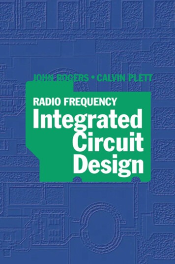
AC CharacteristicsFrequency Response74Ideally, an op-amp should have an infinite bandwidth butpractically op-amp gain decreases at higher frequencies. Sucha gain reduction with respect to frequency is called as roll off.The plot showing the variations in magnitude and phaseangle of the gain due to the change in frequency is calledfrequency response of the op-amp
When the gain in decibels, phase angle in degrees are75plotted against logarithmic scale of frequency, theplot is called Bode PlotThe manner in which the gain of the op-amp changes withvariation in frequency is known as the magnitude plot.The manner in which the phase shift changes with variationin frequency is known as the phase-angle plot.
Obtaining the frequency responseTo obtain the frequency response , consider the highfrequency model of the op-amp with capacitor C at theoutput, taking into account the capacitive effect presentWhereAOLAOL ( f ) 1 j 2 fRoCAOL ( f ) 76AOLf1 j( )foAOL(f) open loop voltage gain as afunction of frequencyAOL Gain of the op-amp at 0HzF operating frequencyFo Break frequency or cutofffrequency of op-amp
For a given op-amp and selected value of C, the frequency fo is constant.77 in the polar form asThe above equation can be writtenAOL ( f ) AOL f 1 fo 2 f AOL ( f ) ( f ) tan f0 1
Frequency Response of an op-amp78
The following observations can be made from the frequency response of an op-ampi) The open loop gain AOL is almost constant from 0 Hz to the breakfrequency fo .ii)Atf fo , the gain is 3dB down from its value at 0Hz . Hence the frequencyfo is also called as -3dB frequency. It is also know as corner frequencyiii) After f fo , the gain AOL (f) decreases at a rate of 20 dB/decade or6dB/octave. As the gain decreases, slope of the magnitude plot is 20dB/decade or -6dB/octave, after f fo .iv) At a certain frequency, the gain reduces to 0dB. This means 20log AOL is0dB i.e. AOL 1. Such a frequency is called gain cross-over frequency orunity gain bandwidth (UGB). It is also called closed loop bandwidth.UGB is the gain bandwidth product only if an op-amp has a single break overfrequency, before AOL (f) dB is zero.79
For an op-amp with single break frequency fo , after fothe gain bandwidth product is constant equal to UGBUGB AOL foUGB is also called gain bandwidth product and denoted as ftThus ft is the product of gain of op-amp and bandwidth.The break frequency is nothing but a corner frequency fo . At thisfrequency, slope of the magnitude plot changes. The op-amp forwhich there is only once change in the slope of the magnitude plot,is called single break frequency op-amp.80
For a single break frequency we can also writeUGB Af ffAf closed loop voltage gainFf bandwidth with feedbackv) The phase angle of an op-amp with single break frequency variesbetween 00 to 900 . The maximum possible phase shift is -900 , i.e. outputvoltage lags input voltage by 900 when phase shift is maximumvi) At a corner frequency f fo , the phase shift is -450.Fo UGB / AOL81
82
The modes of using an op-amp83 Open Loop : (The output assumes one of the twopossible output states, that is Vsat or – Vsat and theamplifier acts as a switch only). Closed Loop: ( The utility of an op-amp can be greatlyincreased by providing negative feed back. The output inthis case is not driven into saturation and the circuitbehaves in a linear manner).
Open loop configurationofop-amp84 The voltage transfer curve indicates the inability of op-ampto work as a linear small signal amplifier in the open loopmode Such an open loop behaviour of the op-amp finds some rareapplications like voltage comparator, zero crossing detectoretc.
Open loop op-amp configurations85 The configuration in which output depends on input, but outputhas no effect on the input is called open loop configuration. No feed back from output to input is used in such configuration. The opamp works as high gain amplifier The op-amp can be used in three modes in open loop configurationthey are1.Differential amplifier2.Inverting amplifier3.Non inverting amplifier
86Differential AmplifierThe amplifier which amplifies the difference between the two inputvoltages is called differential amplifier.V o AOLVd AOL (V1 V2 ) AOL (Vin1 Vin2 )Key point: For very small Vd , output gets driven into saturation dueto high AOL , hence this application is applicable for very small rangeof differential input voltage.
Inverting87AmplifierThe amplifier in which the output is inverted i.e.having 180o phase shift with respect to the input iscalled an inverting amplifierVo -AOL Vin2Keypoint: The negative sign indicates that there is phase shift of 180 obetween input and output i.e. output is inverted with respect to input.
Non-inverting Amplifier88The amplifier in which the output is amplifiedwithout any phase shift in between input andoutput is called non inverting amplifierVo AOL Vin1Keypoint: The positive output shows that input and output are inphase and input is amplified AOL times to get the output.
Why op-amp is generally not used inopen89loop mode?As open loop gain of op-amp is very large, very smallinput voltage drives the op-amp voltage to thesaturation level. Thus in open loop configuration,the output is at its positive saturation voltage ( Vsat) or negative saturation voltage (-Vsat ) depending onwhich input V1 or V2 is more than the other. For a.c.input voltages, output may switch between positiveand negative saturation voltages
This indicates the inability of op-amp to work as a linear smallsignal amplifier in the open loop mode. Hence the op-amp inopen loop configuration is not used for the linear applications
General purposeop-amp74191The IC 741 is high performance monolithic op-amp IC.It is available in 8pin, 10pin or 14pin configuration.It can operate over a temperature of -550 C to 1250C.Features:i) No frequency compensation requiredii) Short circuit protection providediii) Offset Voltage null capabilityiv) Large common mode and differential voltage rangev) No latch up
Internal schematic of 741 op-amp92
93Realistic simplifying assumptions Zero input current: The current drawn by either ofthe input terminals (inverting and non-inverting) iszero Virtual ground :This means the differential inputvoltage Vd between the non-inverting and invertingterminals is essentially zero. (The voltage at the noninverting input terminal of an op-amp can berealistically assumed to be equal to the voltage at theinverting input terminal
Closed loop operation of op-amp94The utility of the op-amp can be increased considerably byoperating in closed loop mode. The closed loop operationis possible with the help of feedback. The feedback allowsto feed some part of the output back to the inputterminals. In the linear applications, the op-amp isalways used with negative feedback. The negativefeedback helps in controlling gain, which otherwisedrives the op-amp out of its linear range, even for a smallnoise voltage at the input terminals
Ideal Inverting Amplifier951.The output is inverted with respect to input, which is indicated byminus sign.2.The voltage gain is independent of open loop gain of the op-amp, whichis assumed to be large.3.The voltage gain depends on the ratio of the two resistances. Henceselecting Rf and R1 , the required value of gain can be easily obtained.4.If Rf R1,, the gain is greater than 1If Rf R1,, the gain is less than 1If Rf R1, the gain is unityThus the output voltage can be greater than, less than or equal to the inputvoltage in magnitude
965.If the ratio of Rf and R1 is K which is other than one, the circuitis called scale changer while for Rf/R1 1 it is called phaseinverter.6.The closed loop gain is denoted as AVF or ACL i.e. gain withfeedback
Ideal Non-inverting Amplifier971.The voltage gain is always greater than one2.The voltage gain is positive indicating that for a.c. input, theoutput and input are in phase while for d.c. input, the outputpolarity is same as that of input3.The voltage gain is independent of open loop gain of op-amp, butdepends only on the two resistance values4.The desired voltage gain can be obtained by selecting propervalues of Rf and R1
Comparison of the ideal inverting and noninverting98 op-ampIdeal Inverting amplifierIdeal non-inverting amplifier1. Voltage gain -Rf/R11. Voltage gain 1 Rf/R12. The output is inverted with2. No phase shift between inputrespect to inputand output3. The voltage gain can be3. The voltage gain is alwaysadjusted as greater than, equal to greater than oneor less than one4. The input impedance is R14. The input impedance is verylarge
Parameter consideration for variousapplicationsFor A.C. applicationsFor D.C. applicationsInput resistanceInput resistanceOutput resistanceOutput resistanceOpen loop voltage gainOpen loop voltage gainSlew rateInput offset voltageOutput voltage swingInput offset currentGain- bandwidth productInput offset voltage and currentdriftsInput noise voltage and currentInput offset voltage and currentdrifts99
Factors affecting parameters of Op-ampSupplyVoltageFrequencyTemperature1. Voltage gain1. Input offset current2. Input resistance2. Input offset voltage3. Output resistance3. Input bias current3. Input voltage range4. CMRR4. Power consumption4. Power consumption5. Input noise voltage5. Gain-Bandwidthproduct5. Input offset current6. Input noise current1. Voltage gain2. Output Voltageswing6. Slew rate7. Input resistance100
101Practical Inverting AmplifierClosed Loop Voltage gain ACL AOL R fR1 R f R1 AOL
Practical Non-Inverting AmplifierACL Closed Loop Voltage gain 102AOL ( R1 R f )R1 R f R1 AOL
AC characteristics103Frequency ResponseHIGH FREQUENCY MODEL OF OPAMP
AC characteristics104Frequency ResponseOPEN LOOP GAIN VS FREQUENCY
Need for frequency compensation inpractical op-amps105 Frequency compensation is needed when large bandwidthand lower closed loop gain is desired. Compensating networks are used to control the phase shiftand hence to improve the stability
Frequency compensation methods106 Dominant- pole compensation Pole- zero compensation
Slew Rate107 The slew rate is defined as the maximum rate of change ofoutput voltage caused by a step input voltage. An ideal slew rate is infinite which means that op-amp’soutput voltage should change instantaneously in responseto input step voltage
108
109
110
1
IMPORTANT POINTS The amplifier output voltage does not depend on the “load” (what is attachedto the output). The “form” of the output voltage (the signs of the scaling factors on the inputvoltages, for example) depends on the amplifier circuit layout.To change the values (magnitudes) of scaling factors, adjust resistor values. Input voltages which are attached to the (non-inverting) amplifier terminalget positive scaling factors.Inputs attached to the – (inverting) terminal get negative scaling factors. You can use these last two principles to design amplifiers which perform aparticular function on the input voltages.1
DIFFERENTIAL AMPLIFIERDifferential AmplifierV V A “Differential”V0 A( V V )V0Circuit Model in linearregionRi V1AV1 Ro V0 V0 depends only on difference (V V-)V0The output cannot be larger thanthe supply voltages, which are notshown. It will limit or “clip” if weattempt to go too far. We call theSlope is Alimits of the output the “rails”.upperrailV V lower railCan add negative feedback to perform an “operation” on input1voltages(addition, integration, etc.): operational amplifier
AMPLIFIER ANALYSIS USING CIRCUITMODELTo analyze an amplifier circuit, you can replace the amplifier with thecircuit model, then make sure the output is within “rails”.Vo AV1 V1 RoRiCircuit Model in linear regionRiVIN1 V1AV1 RoVIN Example: Voltage FollowerV1 VIN VoV0A Ri RoVo VIN( A 1) Ri RoV0
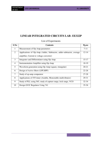
Inverting Op-AmpVOUT VIN1RfR1
Non-Inverting AmplifierVOUT1 R1 VIN 1 R2
Voltage follower1
Instrumentation AmplifierIn a number of industrial and consumer applications, themeasurement of physical quantities is usually done with the helpof transducers. The output of transducer has to be amplified Sothat it can drive the indicator or display system. This function isperformed by an instrumentation amplifier1
Instrumentation Amplifier1
Features of instrumentation amplifier1.2.3.4.5.1high gain accuracyhigh CMRRhigh gain stability with low temperature coefficientlow dc offsetlow output impedance
Differentiator1
1
1
Integrator1Vo (t ) RC1t V0IN(T ) dT VC (0)
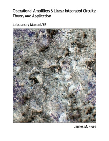
Differential amplifier1
Differential amplifierThis circuit amplifies only the differencebetween the two inputs. In this circuit there aretwo resistors labeled R IN Which means thattheir values are equal. The differential amplifieramplifies the difference of two inputs while thedifferentiator amplifies the slope of an input1
SummerRRRV0 F V1 F V2 F V3R1R2R31
VOLTAGE-TO-CURRENTCONVERTER1Formula: Floating load:- V – I converter.Vin Vid Vf where Vid is input difference voltage andVf is the feedback voltageBut Vid 0Vin Vf R1RLIL Vin/RL
Formula: Ground load V – I converter.I1 I2 IL(Vin-V1)/R (Vo-V1)/R ILVin Vo-2Vi ILRSince op-amp is non invertingGain 1 (R/R) 2Vo 2ViVin Vo-Vo ILRIL Vin/R1
CURRENT-TO-VOLTAGE CONVERTERV0 -is Rf1
1Filter is a frequencyFilterselective circuit that passes signal ofspecified Band of frequencies and attenuates the signals offrequencies outside the bandType of Filter1.Passive filters2. Active filters
Passive filtersPassive filters works well for high frequencies. Butat audio frequencies, the inductors become problematic, asthey become large, heavy and expensive.For low frequencyapplications, more number of turns of wire must be usedwhich in turn adds to the series resistance degradinginductor’s performance ie, low Q, resulting in high powerdissipation1
Active filtersActive filters used op- amp as the active elementand resist
Acquire the knowledge to design linear applications of op amps and also active filters C314.4 Design circuits using Op- amp to generate sinusoidal & non sinusoidal wave forms and explain the operations of 555timer and PLL. C314.5 Analyze data converters (ADC and DAC)