Transcription
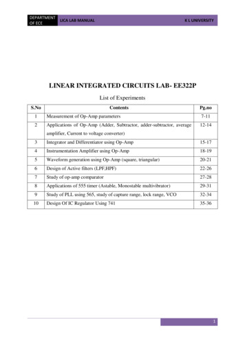
DEPARTMENTLICA LAB MANUALOF ECEK L UNIVERSITYLINEAR INTEGRATED CIRCUITS LAB- EE322PList of ExperimentsS.NoContentsPg.no1Measurement of Op-Amp parameters7-112Applications of Op-Amp (Adder, Subtractor, adder-subtractor, average12-14amplifier, Current to voltage converter)3Integrator and Differentiator using Op-Amp15-174Instrumentation Amplifier using Op-Amp18-195Waveform generation using Op-Amp (square, triangular)20-216Design of Active filters (LPF,HPF)22-267Study of op-amp comparator27-288Applications of 555 timer (Astable, Monostable multivibrator)29-319Study of PLL using 565, study of capture range, lock range, VCO32-3410Design Of IC Regulator Using 74135-361
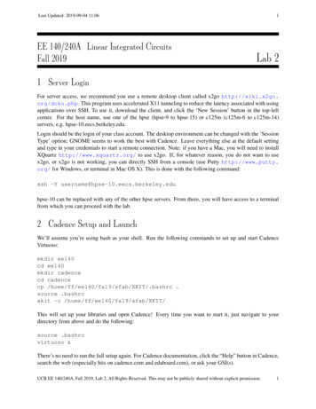
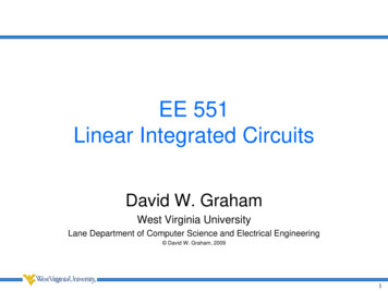
DEPARTMENTLICA LAB MANUALOF ECEK L UNIVERSITY2. APPLICATIONS OF OP-AMPAim: To observe the applications of the op-amp.Apparatus:1)2)3)4)5)Op-Amp (uA- 741)-3 No.sDC Power Supply ( 1 2 - 0 - 12) VCRO(0-20MHz range)Signal Generator (0 -1MHz range)Bread BoardTheory and Procedure:a) Summing Amplifier: Summing amplifier is used to add different voltage valuesapplied at the input.1. Connections are made as per the circuit diagram2. Give input voltages from the DC power supply to the inverting terminal asshown in the figure.3. Measure the output voltage with the help of a multimeter.4. Verify the output voltage with the voltage obtained practically by using theformulaVo -(Rf/R) [V1 V2 V3]b) . Subtractor: A basic differential amplifier can be used as a subtractor, as shown inthe figure. I f a l l the resistors a r e equal in value, then the output voltage can bederived by using superposition principle2
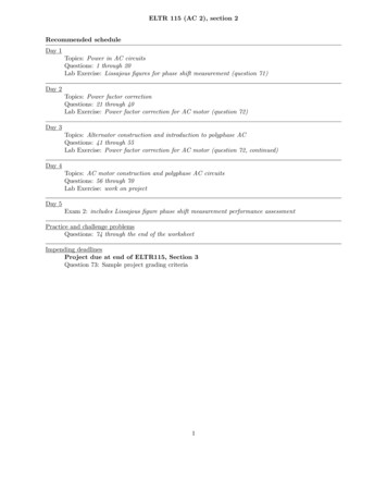
DEPARTMENTLICA LAB MANUALOF ECEK L UNIVERSITY1. Connections are made as per the circuit diagram2. Give input values from the DC power supply to both inverting terminal and noninverting terminals as shown in the figure.3. Measure the output voltage with the help of a multimeter.4. Verify the output voltage with the voltage obtained practically by using the formulaVo [V2 – V1] (since Rf R considered)c). Adder-Subtractor1. Connections are made as per the circuit diagram2. Give input values from the DC power supply to both inverting terminal andnon-inverting terminals as shown in the figure.3. Measure the output voltage with the help of a multimeter.d). Averaging amplifier3
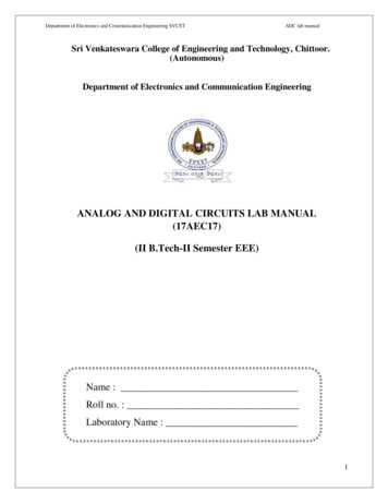
DEPARTMENTLICA LAB MANUALOF ECEK L UNIVERSITY1. Connections are made as per the circuit diagram2. Give input values from the DC power supply to both inverting terminal andnon-inverting terminals as shown in the figure.3. Measure the Average output voltage with the help of a multimeter.The above circuit can be used as an averaging circuit in which the output of the circuit isequal to the average of all the input voltages. This is accomplished by using all resistors ofequal value, Ra Rb Rc RIn addition, the gain by which each input is amplified must be equal to 1 over the number ofinputs; that is, RF/R 1/n. where n is the number of inputs.Thus for a circuit with 3 inputs, consequently from equation3 Vo (Va Vb Vc)/3e). Current to voltage converterPhotocell, photodiode and photovoltaic cell give an output current that is proportional to anincident radiant energy or light. The current through these devices can be converted tovoltage by using a current-to-voltage converter and thereby the amount of light or radiantenergy incident on the photo-device can be measured.Above figure shows an op-amp used as I to V Converter Since the (-) input terminal is atvirtual ground, no current flows through R s and current ii flows through the feedback resistorRf. Thus the output voltage v0 - ii Rf. It may be pointed out that the lowest current that thiscircuit can measure will depend upon the bias current I B of the op-amp. This means that 7414
DEPARTMENTLICA LAB MANUALOF ECEK L UNIVERSITY(IB 3 nA) can be used to detect lower currents. The resistor R f is sometimes shunted with acapacitor Cf to reduce high frequency noise and the possibility of oscillations.Result:Review questions:1) System applications for the 741 op amp?2) What are the uses for a 741 op amp?3) Which amplifier is a summing amplifier with a closed loop gain equal to the reciprocal ofnumber of inputs?4) A current-to-voltage converter produces?Signature of Instructor3. OP-AMP AS INTEGRATOR AND DIFFERENTIATORAim: To observe Op-Amp as integrator and differentiator.Apparatus:1) Op-Amp (µA- 741)3 No.s2) DC Power Supply ( 1 2 - 0 - 12) V3) CRO(0-20MHz range)4) Signal Generator (0 -1MHz range)5) Bread Board6) Resistors 1K, 10K7) Capacitors 0.01ufTheory and Procedure:a). Integrator: Integrators produce output voltages that are proportional to the running time integralof the input voltages. In a running time integral, the upper limit of integration is t.5
DEPARTMENTLICA LAB MANUALOF ECEK L UNIVERSITYIntegrator procedure:1. Connections are made as per circuit diagram.2. Give a square wave input 1 Vpp, 1 KHz from the AC power supply to theinverting terminal as shown in the figure.3. Observe and measure the output wave obtained in the CRO.b). Differentiator: differentiator produce output voltages that are proportional to the differentiationof the input voltages.Simple differentiator without R1 and Cf will not function well since the gain R f/Xc1 increaseswith increase in frequency at a rate of 20dB/decade. This makes the circuit unstable. Inputimpedance Xc1 decreases with increase of frequency which makes the circuit very susceptibleto high frequency noise. When amplified this noise can completely over ride thedifferentiated output signal. The frequency fa is the frequency at which the gain is 0dB.fa 1/(2πRfC1) [ for simple differentiator]fc is the unity gainBandwidth and f is some relative operating frequency. The response of practicaldifferentiator (with Rf and Cf) is given by RED lines. From f to fb the gain increases at20db/decade.6
DEPARTMENTLICA LAB MANUALOF ECEK L UNIVERSITYfb 1/(2πR1C1); R1C1 RfCf if fa fb fcfa 1/(2πRfC1) ;fb 1/(2πR1C1) 1/(2πRfCf);fc unity gain bandwidthThe input signal will be differentiated properly if the time period T of the signal T RfC1.Differentiator procedure:1. Connections are made as per circuit diagram.2. Give a square wave input 1 Vpp, 1 KHz from the AC power supply to theinverting terminal as shown in the figure.3. Observe and measure the output wave obtained in the CRO.4. Verify the output voltage with the voltage obtained practically by using theformulaVo -RfC1dV1 /dtComparison between Integrator and DifferentiatorThe process of integration involves the accumulation of signal over time and hencesudden changes in the signal are suppressed. Therefore an effective smoothing ofsignal is achieved and hence, integration can be viewed as low-pass filtering. Theprocess of differentiation involves identification of sudden changes in the input7
DEPARTMENTLICA LAB MANUALOF ECEK L UNIVERSITYsignal. Constant and slowly changing signals are suppressed by a differentiator. Itcan be viewed as high-pass filtering.Result:Review Questions:1) Why op amp integrator has high value resistor connected across input?2) Why op amp integrators are not used?3) Integrator produces an output that approximates the area under the curve of an inputfunction(T/F)4) differentiator is used to measure .5) Mention the drawback of differentiator.Signature of Instructor4. INSTRUMENTATION AMPLIFIER USING OP-AMPAim: To study the performance of an Instrumentation amplifier.Apparatus:1)2)3)4)5)Op-Amp (µA - 7 4 1 ) - 3 No.sDC Power Supply ( 1 2 - 0 - 1 2) VCRO (0-20MHz range)Resistors 1KΩ, 10KΩBread boardTheory: Instrumentation Amplifier Using Transducer Bridge:Fig shows a simplified differential instrumentation amplifier using a transducer bridge. Aresistive transducer whose resistance changes as a function of some physical energy isconnected in one arm of the bridge with a small circle around it and is denoted by (RT ΔR),where RT is the resistance of the transducer and ΔR is the change in resistance R T.8
DEPARTMENTLICA LAB MANUALOF ECEK L UNIVERSITYThe bridge in the circuit of fig is dc excited but could be ac excited as well. For the balanced bridge atsome reference condition,Vb VaRB(Vdc)/ RB RC RA(Vdc)/RA RTRC / RB RT/ RAGenerally resistors RA,RB, RC are selected so that they are equal in value to the transducerresistance RT at some reference condition. The reference condition is specific value of thephysical quantity under measurement at which the bridge is balanced. This value is normallyestablished by the designer and depends on the transducers characteristics, the type ofphysical quantity to be measured, and the desired application.The bridge is balanced initially at a desired reference condition. However, as the physicalquantity to be measured changes, the resistance of the transducer also changes, which causesthe bridge to unbalance (Va Vb).The output voltage of the bridge can be expressed as afunction off the change in resistance of the transducer.Let the change in resistance of the transducer be ΔR.Since R B and RCare fixed resistors, thevoltage Vb is constant.However,voltage Va varies as a function of the change in transducerresistance.Therefore, according to the voltage divider rule,Va RA(VDC)/RA RT ΔRVb RB(VDC)/RB RCConsequently, the voltage Vab across the output terminals of the bridge isVab Va-Vb (RA(VDC)/RA RT ΔR) - RB(VDC)/RB RCHowever if RA RB RC RT R, then Vab -ΔR(Vdc)/2(2R ΔR)The negative sign indicates the Va Vb because of the increase in the value of ΔR.The output voltage Vout of the bridge is then applied to the differential instrumentationamplifier composed of three op-amps. The voltage followers preceding the basic differentialamplifier help to eliminate the loading of the bridge circuit. The gain of the basic differentialamplifier is (-RF/R1): therefore the output V0 of the circuit isV0 Vab(-RF/R1) [(ΔR)Vdc/2(2R ΔR)] (RF/R1)Generally, the change in resistance of the transducer ΔR is very small. Therefore we canapproximate (2R ΔR) 2R.Thus the output voltageV0 (RF /R1) (ΔR/4R) (VDC)9
DEPARTMENTLICA LAB MANUALOF ECEK L UNIVERSITYThe equation indicates that V0 is directly proportional to the change in resistance ΔR of thetransducer. Since the change in resistance is caused by a change in physical energy, a meterconnected at the output can be calibrated in terms of the units of that physical energy.Result:Practical Gain Value:.Theoretical Gain Value:.Review questions:1) The main purpose of an instrumentation amplifier is to amplify small signals thatare riding on large common-mode voltages.(T/F)2) What is a key characteristic of an instrumentation amplifier?3) The voltage gain of instrumentation amplifier is set by which component4) Instrumentation amplifier is used to measureSignature of Instructor5. WAVEFORM GENERATION USING OP-AMPAim: To generate square wave and triangular wave using Op-AmpApparatus:1)2)3)4)5)Op-Amp (µA - 7 4 1 ) - 2 No’sDC Power Supply ( 1 2 - 0 - 1 2) VCRO (0-20MHz range)Signal Generator (0 to 1MHz range)Bread board10
DEPARTMENTLICA LAB MANUALOF ECEK L UNIVERSITYTheory:We know that the integrator output waveform will be triangular if the input to it is squarewave. It means that a triangular-wave generator can be formed by simply cascading anintegrator and a square-wave generator, as illustrated in figure. This circuit needs a dual opamp, a capacitor, and at least three resistors. The rectangular-wave output of the square-wavegenerator drives the integrator which produces a triangular output waveform.The input of integrator A2 is a square wave and its output is a triangular waveform, the outputof integrator will be triangular wave only when R1 C T/ 2 where T is the (period of squarewave.Procedure:1) Connections are made as per the circuit diagram2) Give the biasing voltage as power to the IC3) Observe the square wave output at 1st op-amp sixth pin and triangular wave output at2nd op-amp sixth pin.4) Adjust the potentiometer to observe the undistorted square wave output.5) Calculate the frequency and amplitude of the square and triangular wave observedfrom the CRO.6) Compare the practical waves obtained with the theoretical valuesResult:Frequency:.Amplitude of square wave:.Amplitude of triangular wave :.Review Questions:1) In which region the op amp is acts like a wave form generator2) Another name for square wave generator is -------------------3) The triangular wave amplitude is depends on -------------------11
DEPARTMENTLICA LAB MANUALOF ECEK L UNIVERSITYSignature of Instructor12
LINEAR INTEGRATED CIRCUITS LAB- EE322P List of Experiments S.No Contents Pg.no 1 Measurement of Op-Amp parameters 7-11 2 Applications of Op-Amp (Adder, Subtractor, adder-subtractor, average amplifier, Current to voltage converter) 12-14 3 Integrator and Differentiator using Op-Amp