Transcription
IJRRAS 17 (1) November 2013www.arpapress.com/Volumes/Vol17Issue1/IJRRAS 17 1 03.pdfCALCULATION OF POWER TRANSFORMERS EQUIVALENT CIRCUITPARAMETERS USING NUMERICAL FIELD SOLUTIONSAntônio Flavio Licarião NogueiraSanta Catarina State University, Joinville, Santa Catarina, BrazilABSTRACTNumerical field solutions may be used to determine the electrical equivalent circuit parameters of transformers. Thelumped elements of the equivalent circuit correspond to the various physical phenomena in the transformer. Thestudy introduces the sequence of operations necessary to evaluate the parameters of the conventional T-shapedtransformer equivalent circuit by means of the numerically simulated open- and short-circuit tests.Keywords: Inductance, Energy storage, Finite element analysis, Transformer cores.1. INTRODUCTIONThe study introduces the sequence of operations necessary to evaluate the parameters of the conventional T-shapedtransformer equivalent circuit by means of the numerically simulated open- and short-circuit tests. The equivalentcircuit for the transformer is shown in figure 1. In this circuit, R1 and R2 represent the resistance of the primary andsecondary windings, respectively. The leakage reactances of the primary and secondary windings are represented byx1 and x2, respectively. The magnetizing reactance is represented by xm, and appears in the circuit’s vertical branch.The resistance Rc accounts for the losses in the magnetic core. In this draw, N1 and N2 denote the number of turns ofthe primary and secondary windings, respectively.Figure 1. Transformer equivalent circuit.Very often, the ideal transformer indicated in figure 1 is omitted in the analysis of large, complex power systemswherein the transformer is only a component part. It is usual among power systems’ analysts to refer all quantities toone side of the transformer, and deal with the equivalent circuit as if it did not contain an ideal transformer. If theturns ratio of the transformer is assumed equal to one, the analysis task is facilitated by the use of the T-shaped,simplified equivalent circuit shown in figure 2. Although study of power transformer performance is usually basedon analysis of sinusoidal steady-state operation at 50 or 60 hertz, only two magnetostatic field solutions are requiredfor the numerically simulated open- and short-circuit tests. Once the calculations of the various parameters indicatedin figure 2 are based on static solutions, the iron loss due to eddy currents cannot be computed. This represents aminor limitation for most power systems analysis tasks, because no-load losses in a transformer are a very small partof the transformer power rating, usually less than 1% [1]. Based on the simplifying assumption of a losslessmagnetic core, only the ohmic loss in the two conductive windings will be taken into account. The ohmic loss of19
IJRRAS 17 (1) November 2013Nogueira Equivalent Circuit Parameters of Transformerseach winding is computed from the known wire resistance [2]. The test problem considered in the present studyconcerns the equivalent circuit of the idealized single-phase shell-type transformer described in [3].Figure 2. T-shaped transformer equivalent circuit.2. PROBLEM DESCRIPTIONThe shell-type transformer under analysis consists of two concentric coils wound around the core’s central limb. Thecore is formed by a magnetically linear material, with a constant relative permeability of 1000. The secondary circuitis wound over the top of the primary. Both windings have equal numbers of turns, and N1 N2 1000. A crosssectional view of the transformer showing the core’s geometry as well as the placement of the two windings appearsin figure 3(a). The geometrical details of the device are indicated in figure 3(b), with the dimensions in meter. Thecentral limb is 0.2 m wide, and all the remaining limbs are 0.1 m wide. The size of each rectangular window is 0.2 mx 0.4 m, and the volume of the windows is completely filled by the two concentric windings. Each coil is modeledby two non-contiguous rectangular regions, and the properties of these regions include the specification of the coil’snumber of turns and terminal current. In addition, each pair of regions representing a stranded coil must be definedas series-connected [4], [5].The numerical model includes a layer of air that surrounds the transformer. The air layerterminates at the artificial, external boundary indicated in figure 3(a). Along the external boundary, the magneticvector potential A is made equal to zero. This boundary condition is commonly referred to as a “Dirichletboundary”, and is used to close the domain of analysis [6]. As indicated in figure 3(b), the depth or length of themodel in the longitudinal or z direction is 0.6 m.The two-dimensional simulation software “finite element methodmagnetics” (FEMM) has been used to obtain the magnetostatic solutions [7]. This is a current-driven finite-elementprogram that works with prescribed currents rather than voltages.Figure 3. (a) Cross sectional view of the transformer’s model; (b) Geometrical dimensions, in meter.20
IJRRAS 17 (1) November 2013Nogueira Equivalent Circuit Parameters of Transformers3. NO-LOAD OPERATION3.1. Problem set upIn the open-circuit test, the secondary is open-circuited, so that the terminal current is I2 0. The primary windingcarries a terminal current I1 2.0 A. In this particular analysis, this small primary current represents 1.0 per cent ofthe rated current.It is worth noting that, in the simulation software FEMM, the number of turns assigned to a givenregion that represents the end-side of a given coil can be either a positive or a negative number. The sign on thenumber of turns indicates the direction of current flow associated with a positive-valued circuit current [7]. For theprimary coil, for example, the number of turns assigned to the coil’s right end-side is 1000, and this produces acurrent flow of 2,000 A, into the plane of analysis. Similarly, the number of turns assigned to the coil’s left endside is -1000, and this produces a current flow of -2,000 A, out of the plane of analysis. Specification of primarycurrents and number of turns is summarized in table 1. In this particular open-circuit test, a magnetomotive force of2,000 ampere-turns is applied to the magnetic core. Directions of current flow into- and out of the plane of analysisare illustrated in figure 4.Table 1. Specification of currents for the open-circuit test.Primary coilTerminalNumber of turnscurrent (A) Left end- Right endsideside2.0-1000 1000Total current (kA)Left end- Right endsideside-2.0 2.0Figure 4. Current flow directions for the open-circuit test.3.2. Results3.2.1. Flux density distributionThe flux density distribution for the transformer’s open-circuit operating condition is shown in figure 5. With the aidof this plot, it is possible to observe that the magnetic flux is confined to the magnetic core. The storage of magneticfield energy in the magnetic core represents 99.8% of the system’s stored energy, and only a tiny percentage of 0.2%of the total energy is stored in the two windows and surrounding air layer. Further inspection of numerical valuesshows that, flux densities B in the transformer’s central and side limbs are, in the mean, 1.77 tesla. These high levels21
IJRRAS 17 (1) November 2013Nogueira Equivalent Circuit Parameters of Transformersof flux densities should be expected because, at no-load operation, the demagnetizing effect of the secondary currentis absent, so most transformers operate at sufficiently high saturation levels.Figure 5. Flux lines for the no-load operating condition.3.2.2. Inductance calculationsThe self- and mutual inductances of the two windings will be calculated using the flux linkage approach [8]. Theself-inductance L1 of the primary winding is given byL1 11it1,[1]where 11 is the flux linkage with the primary, and it1 is the terminal current of the primary winding. For a primaryflux linkage of 211.936 webers and a terminal current of 2.0 A, the calculation yields211.936L1 105.968 H.2.0[2]The mutual inductance M is calculated asM 21it1,[3]where 21 is the flux linkage with the secondary winding. For a secondary flux linkage of 211.686 webers and aprimary terminal current of 2.0 A, the calculation gives211.686M 105.843 H.2.0[4]Once both windings have equal number of turns, the leakage inductance of the primary is defined asl1 L1 M .[5]Substituting the numerical values, the calculation gives l1 0.125 H. Numerical values of flux linkages, selfinductance L1, mutual inductance M and leakage inductance l1 are summarized in table 2.22
IJRRAS 17 (1) November 2013Nogueira Equivalent Circuit Parameters of TransformersTable 2. Parameters related to the open-circuit condition.Flux linkage 11Flux linkage 21Self-inductance L1Mutual inductance MLeakage inductance l1211.936 Wb211.686 Wb105.968 H105.843 H0.125 H4. SHORT-CIRCUIT CONDITION4.1. Problem set upIn the short-circuit test, the secondary terminals are short-circuited, and the primary is supplied by a fraction of itsrated voltage sufficient to produce rated primary current at rated frequency [9]. In the conventional laboratory, asinusoidal current source is connected to the primary terminals. In the simulated work however, it is possible to usethe “bucking test” and a simple magnetostatic analysis to simulate the short-circuit condition. For the bucking test, itis only necessary to prescribe magnetomotive forces of same magnitude and opposing directions in the primary andsecondary windings.For this particular test transformer, with both windings possessing equal number of turns, theprimary and secondary terminal rated currents are equal to 200 A. Specification of currents and number of turns forthe primary and secondary circuits is summarized in table 3. Directions of current flow into- and out of the plane ofanalysis are illustrated in figure 6.Table 3. Specification of currents for the short-circuit test.Primary coilTerminal Number of turnscurrent(A)LeftRightendend-sideside200.0-1000 1000Total(kA)Leftendside-200.0currentRightendside 200.0Secondary coilTerminal Number of turnscurrent(A)LeftRightendsideside200.0 1000-1000end-Figure 6. Directions of current flow for the short-circuit condition.23Total(kA)Leftendside 200.0currentRightendside-200.0
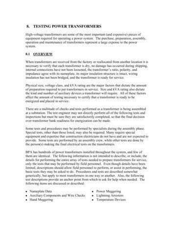
IJRRAS 17 (1) November 2013Nogueira Equivalent Circuit Parameters of Transformers4.2. Results4.2.1. Flux density distributionThe plot of the flux density distribution for the transformer’s short-circuit operating condition is shown in figure 7.Examination of the flux distribution reveals four identical regions wherein the magnetic flux crosses the end-side ofeach winding upwards and returns through the adjacent magnetized portions of the core. Line segments 1-1’, 2-2’and 3-3’ have been added to the plot to ease the identification of these four regions. The fluxes circulate alternatelyin clockwise and anticlockwise directions. Numerical values of flux densities, in millitesla, at selected locations areindicated in the plot of figure 8. Inspected flux densities in the transformer’s core and coil regions are all very closeto 313.0 millitesla. Such levels of flux densities represent approximately 18% of the flux density in the magneticcore at no-load operation. These low levels of flux densities ought to be expected due to the demagnetizing effect ofthe secondary magnetomotive force at short-circuit condition. The storage of magnetic field energy in the regionsoccupied by the two windings represents 99.9% of the system’s total energy, and only a tiny percentage of 0.1% ofthe system’s energy is stored in the magnetic core.Figure 7. Flux lines for the short-circuit condition.24
IJRRAS 17 (1) November 2013Nogueira Equivalent Circuit Parameters of TransformersFigure 8. Flux densities at selected points; values in millitesla.4.2.2. Inductance calculationsIn the short circuit test, the windings are supplied with equal and opposite currents. The leakage inductances can becalculated using the energy approach [8]. If Isc denotes the magnitude of the terminal currents and Wsc the magneticstored energy for the short-circuit condition, the sum of the two leakage inductances is given byl1 l2 2Wsc.( I sc ) 2[6]For set of terminal currents Isc 200.0 A and the resulting magnetically stored energy of 5,007.24 joules, the sum ofthe two leakage inductances is2 5007.24 l1 l 2 0.250 H. 200.0 2[7]Each of the two inductances is assumed to be equal to half of the total, so that[8]l1 l 2 0.125 H.It is worth noting that the two methods of leakage inductance calculation have produced exactly the same value.5. TRANSFORMER EQUIVALENT CIRCUITThe transformer equivalent circuit including numerical values of winding resistances and reactances for an operatingfrequency of 60 hertz is presented in figure 9. All winding resistances are given by the simulation software as a“circuit property” [7]. Computed inductance values coincide very closely with previously published values [3].Figure 9. Numerical values of the transformer parameters; operating frequency of 60 Hz.25
IJRRAS 17 (1) November 2013Nogueira Equivalent Circuit Parameters of Transformers6. CONCLUSIONSThe paper explains how to use static numerical field solutions to obtain the equivalent circuit of a shell-type singlephase power transformer. The study introduces the sequence of numerical operations necessary to simulate thetransformer’s open- and short-circuit tests using finite-element simulation software. During the pre-processing stage,the most important feature is the correct specification of current flow directions in the regions that represent thewindings end-sides. At the post-processing stage, the most important task is the calculation of self- and mutualinductances from the numerical field solutions. Presented numerical results include a detailed analysis of fluxdensity distribution for the two operating conditions. These flux plots bring considerable insight into the subject, andhelp designers and engineers to better understand the storage of magnetic field energy in power transformers.Computed values of the transformer parameters coincide very closely with previously published values.7. ACKNOWLEDGEMENTThe author gives thanks to David Meeker (dmeeker@ieee.org) for the use of the finite element CAD system FEMM.The author also gives thanks to the Brazilian Federal Agency for Postgraduate Studies (CAPES) for the sponsoredaccess to several scientific web sites.8. REFERENCES[1]. N. Chiesa, Power transformer modelling advanced core model, MSc thesis, Politecnico di Milano, Italy,2005, pp. 76-77.[2]. D.A. Lowther and P.P. Silvester, Computer-aided design in magnetics (Springer-Verlag, New York, 1986),pp. 160.[3]. J.D. Edwards, An introduction to MagNet for static 2D modeling (Infolytica Corporation, Montreal, za/Energiestelsels L. Nogueira and L.J.A.S. Maldonado, “Analysis of electromagnetic devices using the principle ofduality between electrical and magnetic circuits together with finite element analysis”, International Journalof Research and Reviews in Applied Sciences, 14(3) 487-497 (2013).[5]. A.F.L. Nogueira and L.J.A.S. Maldonado, “Analysis of AC contactors combining electric circuits, timeharmonic finite element simulations and experimental work”, International Journal of Research and Reviewsin Applied Sciences, 14(3) 513-525 (2013).[6]. A.F.L. Nogueira, “A case study on open boundary techniques for electromagnetic field problems withtranslational symmetry”, Journal of Microwaves, Optoelectronics and Electromagnetic Applications, 9(1) 2033(2010).Available: http://www.sel.eesc.usp.br/jmo/issues/vol 9/v9 n1/v9 n1 paper pdf/regular/v9n1a3.pdf[7]. ual42.pdf[8]. A.F.L. Nogueira, “Techniques for two-dimensional finite-element inductance computation”, InternationalJournal of Research and Reviews in Applied Sciences, 15(2) 168-176 (2013).[9]. G.R. Slemon and A. Straughen, Electric machines (Addison Wesley Publishing Company, London, 1982),pp. 97.26
one side of the transformer, and deal with the equivalent circuit as if it did not contain an ideal transformer. If the turns ratio of the transformer is assumed equal to one, the analysis task is facilitated by the use of the T-shaped, simplified equivalent circuit shown in figure 2. Although study of