Transcription
Dell SC5020 Storage SystemOwner’s Manual
Notes, Cautions, and WarningsNOTE: A NOTE indicates important information that helps you make better use of your product.CAUTION: A CAUTION indicates either potential damage to hardware or loss of data and tells you how to avoid theproblem.WARNING: A WARNING indicates a potential for property damage, personal injury, or death.Copyright 2017 Dell Inc. or its subsidiaries. All rights reserved. Dell, EMC, and other trademarks are trademarks of Dell Inc. or itssubsidiaries. Other trademarks may be trademarks of their respective owners.2017 - 06Rev. A
ContentsAbout This Manual. 5Revision History.5Audience. 5Contacting Dell. 51 SC5020 Storage System Hardware. 6SC5020 Storage System Front-Panel Features and Indicators. 6SC5020 Storage System Back-Panel Features and Indicators. 7SC5020 Storage System Drives. 8SC5020 Storage System Drive Numbering.8SC5020 Storage Controller Features and Indicators . 9SC5020 Storage Controller. 92 Replacing SC5020 Storage System Components. 12Safety Precautions.12Installation Safety Precautions. 12Electrical Safety Precautions.12Electrostatic Discharge Precautions. 13General Safety Precautions.13Bezel. 13Remove the Front Bezel.13Install the Front Bezel.14Hard Drives . 14Identify the Failed Drive.14Remove the Failed Drive. 15Install the Replacement Drive.15Power Supply/Cooling Fan Modules. 15Identify the Failed Power Supply. 15Identify the Failed Cooling Fan. 16Replace a Power Supply/Cooling Fan Module.16Storage Controllers.17Before Working Inside an SC5020 Storage Controller. 18Storage Controller Service Baffle. 18Storage Controller.19Storage Controller Cover.21Battery Backup Unit. 23Riser 1.24I/O Card. 26Mezzanine Card. 29Rack Rails.32Remove the Rack Rails.32Install the Rack Rails.323
Power Up the Storage Center Hardware. 333 SC5020 Storage System Technical Specifications. 34Technical Specifications.344
About This ManualThis manual describes the features and technical specifications of an SC5020 storage system.Revision HistoryDocument Number: 680-138-001RevisionDateDescriptionAJune 2017Initial releaseAudienceThe information provided in this manual is intended for use by Dell end users.Contacting DellDell provides several online and telephone-based support and service options. Availability varies by country and product, and someservices might not be available in your area.To contact Dell for sales, technical support, or customer service issues, go to www.dell.com/support. For customized support, type your system service tag on the support page and click Submit. For general support, browse the product list on the support page and select your product.About This Manual5
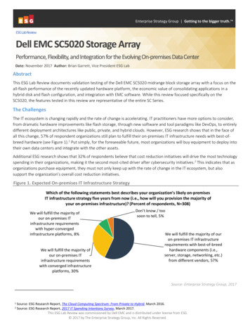
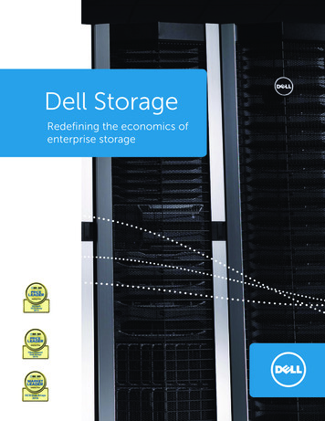
1SC5020 Storage System HardwareThe SC5020 storage system ships with Dell Enterprise drives, two redundant power supply/cooling fan modules, and two redundantstorage controllers.Each storage controller contains the front-end, back-end, and management communication ports of the storage system.SC5020 Storage System Front-Panel Features and IndicatorsThe front panel of the SC5020 contains power and status indicators, and a system identification button.In addition, the hard drives are installed and removed through the front of the storage system chassis.Figure 1. SC5020 Storage System Front-Panel ViewItemName1Power indicatorIconDescriptionLights when the storage system power is on 2Status indicatorLights when at least one power supply is supplying power to the storagesystem 3Identification buttonSC5020 Storage System HardwareOff – No powerOn steady blue – Power is on and firmware is runningBlinking amber – Fault detectedBlinking blue continuously – A user sent a command to the storage system tomake the LED blink so that the user can identify the storage system in therack. 6Off – No powerOn steady green – At least one power supply is providing power to thestorage systemThe identification LED blinks on the control panel of the chassis, to allowusers to find the storage system when looking at the front of the rack.
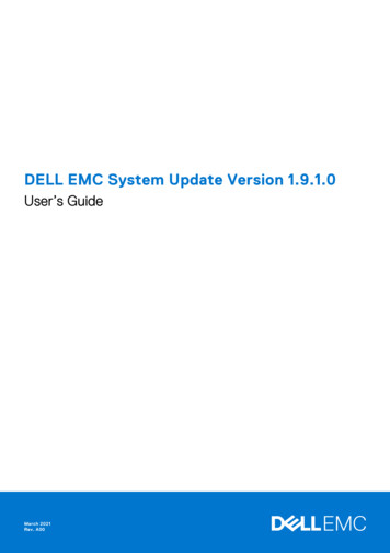
ItemNameIconDescription 4Hard drives—The identification LEDs on the storage controllers also blink, which allowsusers to find the storage system when looking at the back of the rack.Can have up to 30 internal 2.5-inch SAS hard drivesSC5020 Storage System Back-Panel Features and IndicatorsThe back panel of the SC5020 contains the storage controller indicators and power supply indicators.Figure 2. SC5020 Storage System Back-Panel ViewItemName1Power supply/coolingfan module (2)2Storage controller (2)IconDescriptionContains a 1485 W power supply and fans that provide cooling for the storagesystem, with AC input to the power supply of 200–240 V. In Dell StorageManager, the power supply/cooling fan module on the left side of the backpanel is Power Supply 1 and power supply/cooling fan module on the right sideof the back panel is Power Supply 2.An LED behind the LED handle indicates whether the power supply has AC/input power. Green – A valid power source is connected to the power supply and thepower supply is operational. Not lit – The power supply is off or the power source has a fault.—Each storage controller contains: 3Power switch (2)—Mezzanine card with four SFP ports or four RJ45 10GBASE-T portsOne expansion slot a front-end I/O card:– Fibre Channel– iSCSI– SASSAS expansion ports – Two 12 Gbps SAS ports for back-end connectivityto expansion enclosuresUSB port – Single USB 2.0 portMGMT port – Embedded Ethernet port for system managementSerial port – Micro-USB serial port used for an alternative initialconfiguration and support-only functionsControls power for the storage system. Each power supply/cooling fan modulehas one power switch.SC5020 Storage System Hardware7
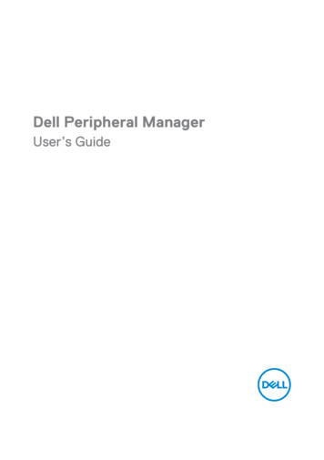
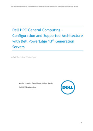
ItemNameIconDescription4Power supply/coolingfan module LED handle—The handle of the power supply/cooling fan module indicates the DC powerstatus of the power supply and the fans. 5Power socket (2)—Not lit – No powerSolid green – Power supply has valid power source and is operationalBlinking amber – Error condition in the power supplyBlinking green – Firmware is being updated.Blinking green then off – Power supply mismatchAccepts the following standard computer power cords: IEC320-C13 for deployments worldwideIEC60320-C19 for deployments in JapanSC5020 Storage System DrivesThe SC5020 storage system supports Dell Enterprise Plus Premium drives.The drives in the SC5020 storage system are installed horizontally. The indicators on the drives provide status and activityinformation.Figure 3. SC5020 Storage System Drive IndicatorsItemControl/FeatureIndicator Code1Drive activity indicator Blinking green – Drive has I/O activitySteady green – Drive is detected and has no faults2Drive status indicator Steady green – Normal operationBlinking green – A command was sent by Dell Storage Manager to the drive to makethe LED blink so that users can identify the drive in the rack.Blinking amber – Hardware or firmware fault SC5020 Storage System Drive NumberingAn SC5020 holds up to 30 drives, which are numbered from left to right in rows starting from 0 at the top-left drive. Drive numbersincrement from left to right, and then top to bottom such that the first row of drives is numbered from 0 to 4 from left to right, andthe second row of drives is numbered from 5 to 9 from left to right.The Dell Storage Manager identifies drives as XX-YY, where XX is the number of the unit ID of the storage system and YY is thedrive position inside the storage system.Figure 4. SC5020 Drive Numbering8SC5020 Storage System Hardware
SC5020 Storage Controller Features and IndicatorsThe SC5020 storage system includes two storage controllers in two interface slots.SC5020 Storage ControllerThe following figure shows the features and indicators on an SC5020 storage controller.Figure 5. SC5020 Storage ControllerItemControl/Feature1I/O card slotIconDescriptionFibre Channel I/O card – Ports are numbered 1 to 4 from left to right The LEDs on the 16 Gb Fibre Channel ports have the following meanings: – All off – No power– All on – Booting up– Blinking amber – 4 Gbps activity– Blinking green – 8 Gbps activity– Blinking yellow – 16 Gbps activity– Blinking amber and yellow – Beacon– All blinking (simultaneous) – Firmware initialized– All blinking (alternating) – Firmware faultThe LEDs on the 32 Gb Fibre Channel ports have the following meanings:––––––––All off – No powerAll on – Booting upBlinking amber – 8 Gbps activityBlinking green – 16 Gbps activityBlinking yellow – 32 Gbps activityBlinking amber and yellow – BeaconAll blinking (simultaneous) – Firmware initializedAll blinking (alternating) – Firmware faultiSCSI I/O card – Ports are numbered 1 to 4 from left to rightNOTE: The iSCSI I/O card supports Data Center Bridging (DCB), butthe mezzanine card does not support DCB. The LEDs on the iSCSI ports have the following meanings:– Off – No powerSC5020 Storage System Hardware9
ItemControl/FeatureIconDescription– Steady Amber – Link– Blinking Green – ActivitySAS I/O card – Ports are numbered 1 to 4 from left to rightThe SAS ports on SAS I/O cards do not have LEDs.2Identification LEDBlinking blue continuously – A command was sent by Dell Storage Manager tothe storage system to make the LED blink so that users can identify thestorage system in the rack.The identification LED blinks on the control panel of the chassis, which allowsusers to find the storage system when looking at the front of the rack.The identification LEDs on the storage controllers also blink, which allowsusers to find the storage system when looking at the back of the rack.3Cache to Flash (C2F) Off – Running normallyBlinking green – Running on battery4Health status Off – UnpoweredAmber – Powering upBlinking amber – Slow blinking amber (2s on, 1s off) – Controller hardware fault wasdetected. Use Dell Storage Manager to view specific details about thehardware fault.– Fast blinking amber (4x per second) – Power good and the preoperating system is bootingBlinking green – Slow blinking green (2s on, 1s off) – Operating system is booting– Blinking green (1s on, 1s off) – System is in safe mode– Fast blinking green (4x per second) – Firmware is updatingSolid green – Running normal operation5Serial port (micro USB)Used under the supervision of Dell Technical Support to troubleshoot andsupport systems.6MGMT port7USB portOne USB 2.0 connector that is used for SupportAssist diagnostic files whenthe storage system is not connected to the Internet.8Mini-SAS port B (ports 1and 2)Back-end expansion ports 1 and 2. LEDs with the ports indicate connectivityinformation between the storage controller and the expansion enclosure:—Ethernet port used for storage system management and access to DellStorage Manager.Two LEDs with the port indicate link status (left LED) and activity status(right LED): Link and activity indicators are off – Not connected to the network Link indicator is green – The NIC is connected to a valid network at itsmaximum port speed. Link indicator is amber – The NIC is connected to a valid network at lessthan its maximum port speed. Activity indicator is blinking green – Network data is being sent orreceived. 10SC5020 Storage System HardwareSteady green indicates the SAS connection is working properly.Steady yellow indicates the SAS connection is not working properly.
ItemControl/Feature9Mezzanine cardIconDescriptionThe iSCSI ports on the mezzanine card are either 10 GbE SFP ports or 1GbE/10 GbE RJ45 ports.The LEDs on the iSCSI ports have the following meanings: Off – No connectivity Steady green, left LED – Link (full speed) Steady amber, left LED – Link (degraded speed) Blinking green, right LED – ActivityNOTE: The mezzanine card does not support DCB.SC5020 Storage System Hardware11
2Replacing SC5020 Storage System ComponentsThis chapter describes how to remove and install components of the SC5020 storage system.This information assumes that you have received the replacement component and are ready to install it.Safety PrecautionsAlways follow these safety precautions to avoid injury and damage to Storage Center equipment.If equipment described in this section is used in a manner not specified by Dell, the protection provided by the equipment could beimpaired. For your safety and protection, observe the rules described in the following sections.NOTE: See the safety and regulatory information that shipped with each Storage Center component. Warrantyinformation is included within this document or as a separate document.Installation Safety PrecautionsFollow these safety precautions: Dell recommends that only individuals with rack-mounting experience install the SC5020 in a rack. You need at least two people to lift the storage system chassis from the shipping box and to install it in the rack. Make sure the storage system is always fully grounded to prevent damage from electrostatic discharge. When handling the storage system hardware, use an electrostatic wrist guard (not included) or a similar form of protection.The chassis must be mounted in a rack. The following safety requirements must be considered when the chassis is being mounted: The rack construction must be capable of supporting the total weight of the installed chassis. The design should incorporatestabilizing features suitable to prevent the rack from tipping or being pushed over during installation or in normal use. When installing multiple chassis in a rack, fill from the bottom up and empty from the top down. To avoid danger of the rack toppling over, slide only one chassis out of the rack at a time.Electrical Safety PrecautionsAlways follow electrical safety precautions to avoid injury and damage to Storage Center equipment. Provide a suitable power source with electrical overload protection. All Storage Center components must be grounded beforeapplying power. Make sure that a safe electrical earth connection can be made to power supply cords. Check the groundingbefore applying power. The plugs on the power supply cords are used as the main disconnect device. Make sure that the socket outlets are located nearthe equipment and are easily accessible. Know the locations of the equipment power switches and the room's emergency power-off switch, disconnection switch, orelectrical outlet. Do not work alone when working with high-voltage components. Use rubber mats specifically designed as electrical insulators. Do not remove covers from the power supply unit. Disconnect the power connection before removing a power supply from thestorage system. Do not remove a faulty power supply unless you have a replacement model of the correct type ready for insertion. A faulty powersupply must be replaced with a fully operational module power supply within 24 hours. Unplug the storage system chassis before you move it or if you think it has become damaged in any way. When powered bymultiple AC sources, disconnect all power sources for complete isolation.12Replacing SC5020 Storage System Components
Electrostatic Discharge PrecautionsAlways follow electrostatic discharge (ESD) precautions to avoid injury and damage to Storage Center equipment.Electrostatic discharge (ESD) is generated by two objects with different electrical charges coming into contact with each other. Theresulting electrical discharge can damage electronic components and printed circuit boards. Follow these guidelines to protect yourequipment from ESD: Dell recommends that you always use a static mat and static strap while working on components in the interior of the chassis. Observe all conventional ESD precautions when handling plug-in modules and components. Use a suitable ESD wrist or ankle strap. Avoid contact with backplane components and module connectors. Keep all components and printed circuit boards (PCBs) in their antistatic bags until ready for use.General Safety PrecautionsAlways follow general safety precautions to avoid injury and damage to Storage Center equipment. Keep the area around the storage system chassis clean and free of clutter. Place any system components that have been removed away from the storage system chassis or on a table so that they are notin the way of other people. While working on the storage system chassis, do not wear loose clothing such as neckties and unbuttoned shirt sleeves. Theseitems can come into contact with electrical circuits or be pulled into a cooling fan. Remove any jewelry or metal objects from your body. These items are excellent metal conductors that can create short circuitsand harm you if they come into contact with printed circuit boards or areas where power is present. Do not lift the storage system chassis by the handles of the power supply units (PSUs). They are not designed to hold theweight of the entire chassis, and the chassis cover could become bent. Before moving the storage system chassis, remove the PSUs to minimize weight. Do not remove drives until you are ready to replace them.NOTE: To ensure proper storage system cooling, hard drive blanks must be installed in any hard drive slot that is notoccupied.BezelThe front bezel is a cover for the front panel of the SC5020 storage system.Remove the Front BezelBefore you remove or install hard drives in the storage system, remove the front bezel.1.Use the system key to unlock the keylock at the left end of the bezel.2.Lift the release latch next to the keylock.3.Rotate the left end of the bezel away from the front panel.4.Unhook the right end of the bezel and pull the bezel away from the storage system.Replacing SC5020 Storage System Components13
Figure 6. Installing and Removing the Bezel1.Keylock2.Front bezelInstall the Front BezelTo secure the storage system, install the front bezel.1.Hook the right end of the replacement bezel onto the front panel of the storage system.2.Insert the left end of the bezel into the securing slot until the release latch locks into place.3.Secure the bezel with the keylock.Hard DrivesThe SC5020 storage system supports hot-swappable hard drives.A minimum of 4 SSDs or 7 drives must be installed in the chassis or in an expansion enclosure. The SC5020 storage system supportsa maximum of 30 drives installed in the chassis. The drives are installed from left to right, and then top to bottom. The first row ofdrives are numbered from 0–4 from left to right, the second row of drives are numbered from 5–9 from left to right, and so on.The Dell Storage Manager identifies drives as XX-YY, where XX is the number of the unit ID of the storage system and YY is thedrive position inside the storage system.Figure 7. SC5020 Drive NumberingIdentify the Failed DriveTo determine which drive failed, use the Dell Storage Manager.1.Click the Hardware tab.2.In the Hardware tab navigation pane, select the Enclosures node.14Replacing SC5020 Storage System Components
3.Click the Disks tab.4.Find the drive with the status of Down.5.Record the location of the drive from the Name column.Remove the Failed DriveUse this procedure to remove a failed drive from the SC5020 storage system.PrerequisitesBefore removing the drive, make sure that the following alert is displayed in the Alerts tab of Dell Storage Manager:Drive # is ready to be removed., where # is the drive position in the storage system.Steps1. Remove the front bezel from the storage system.2.Locate the failed hard drive in the storage system.3.Press the release button to open the hard drive carrier release handle.4.Slide the hard drive carrier out of the hard drive slot.Install the Replacement DriveUse this procedure to install a drive in the SC5020 storage system.Steps1. Open the release handle on the drive carrier and insert the hard drive carrier into the open drive slot.2.Slide the drive into the slot until the drive carrier contacts the midplane.3.Close the drive carrier handle to lock the drive in place.4.Continue to push firmly until you hear a click and the drive carrier handle fully engages.5.Clear the drive swap status from the Hardware tab in Dell Storage Manager.For instructions, see the Dell Dell Storage Manager Administrator’s Guide.Next stepsInstall the front bezel on the storage system.Power Supply/Cooling Fan ModulesThe SC5020 storage system supports two hot-swappable power supply/cooling fan modules.The cooling fans that cool the storage system and the power supplies are integrated into the power supply/cooling fan module andcannot be replaced separately. If one power supply/cooling fan module fails, the second module continues to provide power to thestorage system.NOTE: When a power supply/cooling fan module fails, the cooling fan speed in the remaining module increasessignificantly to provide adequate cooling. The cooling fan speed decreases gradually when a new power supply/coolingfan module is installed.CAUTION: A single power supply/cooling fan module can be removed from a powered-on storage system for no morethan 90 seconds. If a power supply/cooling fan module is removed for longer than 90 seconds, the storage system mightshut down automatically to prevent damage.Identify the Failed Power SupplyTo determine which power supply failed, use the Dell Storage Manager.1.Click the Hardware tab.2.In the Hardware tab navigation pane, click Power Supply.3.Find the power supply with a status of Down.4.Record the location of the failed power supply.Replacing SC5020 Storage System Components15
Identify the Failed Cooling FanTo determine which cooling fan failed, use the Dell Storage Manager.1.Click the Hardware tab.2.Click the Fan Sensor node.3.Find the fan with a status of Down.4.Record the location of the power supply in which the fan has failed.Replace a Power Supply/Cooling Fan ModuleUse this procedure to replace failed a power supply/cooling fan module.Prerequisites1.Use Dell Storage Manager to send SupportAssist information to Dell Technical Support. For more information, see the Dell DellStorage Manager Administrator’s Guide.2.Contact Dell Technical Support to let them know that you are performing a repair.About this taskYou can replace power supply/cooling fan modules one at a time without shutting down the storage system.Steps1. Press the power switch on the power supply/cooling fan module to turn it off.To prevent the module from overheating, replace it within 3 minutes.2.Remove the hook-and-loop strap that secures the power cable to the LED handle and disconnect the power cable from thepower supply/cooling fan module.Figure 8. Removing the Hook and Loop Strap from the Power Cable3.Push the release tab on the power supply/cooling fan module to the right and use the handle to slide the module out of thechassis.CAUTION: The power supply/cooling fan modules are heavy. To avoid injury, use both hands while removing themodule.16Replacing SC5020 Storage System Components
Figure 9. Removing a Power Supply/Cooling Fan Module1.Power supply/cooling fan module2.Power socket3.Release tab4.Power supply/cooling fan module LED handle5.Power switch4.Slide the replacement power supply/cooling fan module into the chassis until it is fully seated and the release tab clicks intoplace.5.Connect the power cable to the power supply/cooling fan module and make sure the cable is plugged into a power outlet.6.Secure the power cable using the hook-and-loop strap.7.Press the power switch on the power supply/cooling fan module to turn it on.NOTE: Allow several seconds for the storage system to recognize the power supply/cooling fan module anddetermine its status. When the power supply/cooling fan module is functioning properly, the AC power statusindicator turns green and the power supply/cooling fan status indicator is off.8.In Dell Storage Manager, make sure that the replacement power supply is recognized and shows as up and running.Next steps1.Use Dell Storage Manager to send SupportAssist information to Dell Technical Support2.Contact Dell Technical Support to let them know that you have completed a repair.Storage ControllersUse this procedure to remove a storage controller from the chassis.Remove a storage controller if it fails or if a component inside the storage controller fails.CAUTION: A label on the cover of each storage controller indicates the slot in which the storage controller is to beinstalled. Storage control
The SC5020 storage system ships with Dell Enterprise drives, two redundant power supply/cooling fan modules, and two redundant storage controllers. Each storage controller contains the front-end, back-end, and management communication ports of the storage system. SC5020 Storage System Front-Panel Features and Indicators