Transcription
ELG4125: Lecture 2Power TransformersThe Ideal TransformerThe Real TransformerEquivalent Circuits for Practical TransformersThe Per-Unit SystemThree-Phase TransformersAutotransformers
Transformers in Power Systems Typically in power systems, voltages get transformedapproximately five times between generation and delivery tothe users. Generation in power systems, primarily by synchronousgenerators, takes place at around 20-kV level. Transmission voltages of 230 kV, 345 kV, 500 kV, and 765 kV iscommon. At the load, these voltages are stepped down to 120/240 Vsingle-phase in residential usage. Another advantage of transformers in many applications is toprovide electrical insulation for safety purposes.
Real TransformersTransformer TypesPower TransformersCurrent TransformersVoltage TransformersTransformer ConnectionsSeries TransformersEach leg is a single phase transformerTransformer Purchasing IssuesY-Y connections (no phase shift)EfficiencyD-D connections (no phase shift)Audible NoiseY-D connections (-30 degrees phase shift)Installation CostsD-Y connections ( 30 degrees phase shift)Manufacturing FacilitiesPerformance Record
Nameplate Information kVA is the apparent power. Voltage ratings for high and low side are no-load values. Thesymbol between the values indicate how the voltages arerelated: Long dash (—) From different windings. Slant (/) from same winding: 240/120 is a 240 V winding with a center tap. Cross (X) Connect windings in series or parallel. Not used inwye-connected winding: 240X120 two part winding connected in series for 240 or parallelfor 120. Wye (Y) A wye-connect winding.
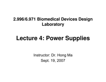
Basic Principles of Transformer Operation Transformers consist of two or more coupled windings wherealmost all of the flux produced by one winding links the otherwinding.
Transformer Exciting Current Transformers use ferromagnetic materials that guide magneticflux due to their high permeability, require small ampereturns to produce the desired flux density. The magnetising current is that current which flows in theprimary winding when the primary voltage is applied with thesecondary unloaded. It is the necessary current that satisfiesthe excitation condition as determined by the fundamentaltransformer equation. In modern power transformer of large kVA ratings, themagnetizing currents in their normal operating region are verysmall, for example, well below 0.2% of the rated current atthe rated voltage.
Voltage TransformationvP eP N P d dtvS eS N Sd dtThe EMF of a transformer at a given flux density increases with frequency. Byoperating at higher frequencies, transformers can be physically more compactbecause a given core is able to transfer more power without reachingsaturation and fewer turns are needed to achieve the same impedance.However, core loss and conductor skin effect also increase with frequency.Aircraft and military equipment employ 400 Hz power supplies which reducecore and winding weight. Conversely, frequencies used for some railwayelectrification systems were much lower (16.7 Hz and 25 Hz) than normalutility frequencies (50/60 Hz) for historical reasons concerned mainly with thelimitations of early electric traction systems.As such, the transformers used to step down the high over-head line voltages(15 kV) were much heavier for the same power rating than those designedonly for the higher frequencies.
EP 2π2 max f NP φmax 4.44 f NP φmaxVP4.44 f NP Where VP is the RMS value of the applied voltage with theassumption that eP VP. The second Equation shows that the flux isdetermined by the applied voltage, the frequency of operation, andnumber of turns in the winding.
Example
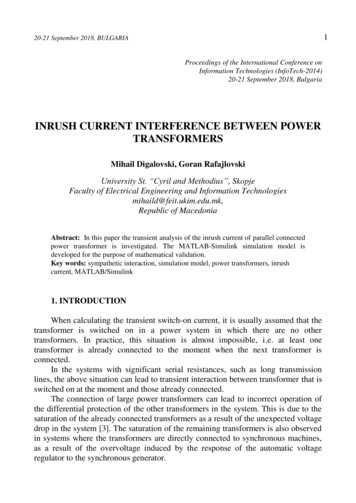
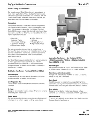
Transformer Equivalent CircuitViewed from the Primary Side
Modeling a Real Transformer
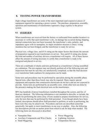
Equivalent Circuit with ParametersMoved to the Primary Side
Transformer Phasor Diagram
Transformer TestsTest to Determine Transformer Parameters, we require to conductOpen Circuit Test:Energize Low voltage winding at rated voltage, leaving other winding openMeasure Current (Ioc) and Power (Poc) into energized winding.Calculate parametersShort Circuit Test:Energize Low current (high voltage) winding at rated current with a solid shortcircuit applied across the other windingMeasure Voltage and Power at terminals of energized windingCalculate parameters
Transformer TestOpen-Circuit TestSICPCS , andVSI CS RCSShort-Circuit Test I - I S2eV SS , andICX mS VSI mSS2C2RT PSC2I SCXT VSC - RT2 I SC
Example 1
Example 2
The Per unit system In the per-unit system, the voltages, currents, powers,impedances, and other electrical quantities areexpressed on a per-unit basis by the equation:Quantity per unit Actual valueBase value of quantity It is customary to select two base quantities to define agiven per-unit system. The ones usually selected arevoltage and power.
Vb VratedSb SratedThen compute base values for currents and impedancesSbIb Vb2Vb VbZb I b Sb
V p.u .Vactual VbS p.u.S actual SbI p.u.Z p .u .Z % Z p.u. 100%I actual IbZ actual Zb
Example 1
Example 2An electrical load is rated 120 volts, 500 watts. Computethe per-unit and percent impedance of the load. Give theper unit equivalent circuit.V2V2(120) 2P R 28.8 RP500Power factor 1.0Z 28.8 0 23
Select base quantitiesSb 500VAVb 120VCompute base impedanceVb2 (120) 2Zb 28.8 Sb500The per-unit impedance isZ p.u.24Z28.8 0 1 0p.u.Zb28.8
Percent impedance:Z % 100%Per-unit equivalent circuit:VS 1 0 p.u.25Z 1 0 p.u.
Per-unit System for Single Phase CircuitsOne-phase circuitsSb S1- V I whereV Vline-to-neutralI I line-currentVbLV V LVVbHV V HVSb VbLVSb VbHVI bLV26I bHV
Z bLV27VbLV (VbLV ) 2 I bLVSbZ bHVVbHV (VbHV ) 2 I bHVSbS*S pu V pu I puSbPPpu V pu I pu cos SbQQ pu V pu I pu sin Sb
Transformation Between BasesSb1 S AVb1 VAVb21Z b1 Sb1ZLZ pu1 Z b1And secondSb 2 S BZb2282b2V Sb 2Vb 2 VBZ pu2ZL Zb2
Transformation Between BasesZ pu2Z pu1Z L Z b1 Z b1 Vb21 Sb 2 2Z b 2 Z L Z b 2 Sb1 Vb 22Z pu2 Vb1 Sb 2 Z pu1 Vb 2 Sb1 “1” – old“2” - new2 Vb,old Sb,new Z pu,new Z pu,old S V b,new b,old 29
Transformation Between BasesGenerally per-unit values given to another base can beconverted to new base by the equations:Sbase1( P, Q, S ) pu on base 2 ( P, Q, S ) pu on base 1Sbase2Vbase1V pu on base 2 V pu on base 1Vbase2( R, X , Z ) pu on base 2(Vbase1 ) 2 Sbase2 ( R, X , Z ) pu on base 1(Vbase2 ) 2 Sbase1When performing calculations in a power system, everyper-unit value must be converted to the same base.30
Per-unit System for Single Phase TransformerConsider the equivalent circuit of transformer referred toLV side and HV side shown below:RSXS j 22aaRS jX SVLVVHVVLVN1N2DefineSReferred to LV side31VHVVLVN1a 1VHV N 2Referred to HV side
Per-unit System for Single Phase TransformerChooseVb1 VLV ,ratedSb SratedComputeVHV1Vb 2 Vb1 Vb1VLVaVb22Vb21Zb2 Z b1 SbSb32Z b1 Vb21Vb212 2 aZ b 2 Vb 2 ( 1 V ) 2b1a
Per-unit System for Single Phase TransformerPer-unit impedances areRS jX SZ p.u.1 Z b1Z p.u.2RS jX SRS jX S 2 222RS jX Saaaa Z b1Zb2Z b1a2Z p.u.1 Z p.u.233
Voltage RegulationVoltage regulation is defined asVR Vno-load - V full-loadV full-load 100%In per-unit systemVR V pu,no-load - V pu, full-loadV pu, full-load 100%Vfull-load: Desired load voltage at full load. It may be equal to, above, orbelow rated voltage.Vno-load: The no load voltage when the primary voltage is the desiredvoltage in order the secondary voltage be at its desired valueat full load.34
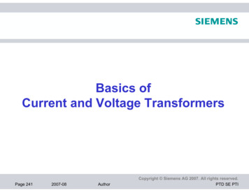
ExampleA single-phase transformer rated 200-kVA, 200/400-V, and10% short circuit reactance. Compute the voltageregulation when the transformer is fully loaded at unitypower factor and rated voltage 400-V.Vb 2 400VSb 200kVASload, pu 1 0 puX S , pu j 0.1 pu35VPj 0.1XSVSSload
Rated voltageVS , pu 1.0 0 pu*I load, pu Sload, pu 1.0 0 * 1.0 0 pu V 1.0 0 S , pu VP , pu VS , pu I pu X S , pu 1.0 0 1.0 0 j 0.1 1 j 0.1 1.001 5.7 o pu36
Secondary sideVpu, full-load VS , pu 1.0 0 puVpu,no-load VP, pu 1.001 5.7o puVoltage regulationVR V pu,no-load - V pu, full-loadV pu, full-load1.001 - 1.0 100% 0.1%1.037 100%
Problemj100 G20 kV22kV/220kV80MVA14%220kV/20kV 50MVA50MVA0.8 PF10%laggingSelect Vbase in generator circuit and Sb 100MVA, compute theper unit equivalent circuit.38
Residential Distribution TransformersSingle phase transformers are commonly used inresidential distribution systems. Most distributionsystems are 4 wire, with a multi-grounded, commonneutral.39
Three-Phase Transformers
Per-unit System for Three Phase CircuitsSb S3- 3S1- 3V I V Vline-to-neutral VL (line) / 3I I line-current I LSb 3VL I LVbLV VL, LVVbHV VL, HVSb 3VbLV I bLV 3VbHV I bHV41
Per-unit System for Three Phase CircuitsSb 3VbLVI bLVZ bLV Z bHVS pu42V LVI LVVbLV 3I bHV3VbLV (VbLV ) 2 SbSb(VbHV ) 2 Sb3VL I L* V pu I *puSb3Vb I bS3 Sb 3VbHV
Per-unit System for Three Phase TransformerThree 25-kVA, 34500/277-V transformers connected in DY. Short-circuit test on high voltage side:VLine,SC 2010VI Line,SC 1.26 AP3 ,SC 912WDetermine thetransformer.43per-unitequivalentcircuitofthe
Per-unit System for Three Phase TransformerUsing Y-connection equivalent circuitI SC 1.26VSCRS jX S2010 3Sb 25000VA345002773VSC2010 1160.47V3Z SC1160.47 921.00 1.2644
Per-unit System for Three Phase Transformer912P 304W3XS RS P 2I SC 304 191.48 21.26Z SC - RS2 9212 - 191.482 900.86 2Z SC 191.48 j900.86 Sb 25000VAZ b,HV19918.582 15869.99 25000Z SC, pu,Y45Vb, HV34500 19918.58V3191.48 j900.86 0.012 j 0.0568 pu15869.99
Per-unit System for Three Phase TransformerUsing D-connection equivalent circuit1.26I SC Z SC,D3Sb 25000VAVSC 201034500 277VSC 2010VZ SC,D46I SC2010 2764.79 0.7271.26 0.727 A3
Per-unit System for Three Phase Transformer912P 304W3RS ,D P 2I SC 304 575.18 20.7272X S ,D Z SC,D - RS2,D 2764.792 - 575.182 2704.30 Z SC 191.48 j900.86 Sb 25000VAZ b,HVZ SC, pu,D47Vb, HV 34500V345002 47610 25000575.18 j1704.30 0.012 j 0.0568 pu47610
Transformer EfficiencyPoutOutput power Pout Input powerPinPout PlossPout VS IS cos θVS IS cos θ 100 VS IS cos θ PCu PC
Load Tap Changing Transformers LTC transformers have tap ratios that can be varied to regulatebus voltages. The typical range of variation is 10% from the nominal values,usually in 33 discrete steps (0.0625% per step). Because tap changing is a mechanical process, LTC transformersusually have a 30 second dead-band to avoid repeated changesto minimize wear and tear. Unbalanced tap positions can cause “circulating VARs;” that is,reactive power flowing from one winding to the next in a threephase transformer.49
Phase Shifting Transformers Phase shifting transformers are used to control the phaseangle across the transformer. Since power flow through the transformer depends uponphase angle, this allows the transformer to regulate thepower flow through the transformer. Phase shifters can be used to prevent inadvertent "loop flow"and to prevent line overloads.50
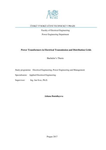
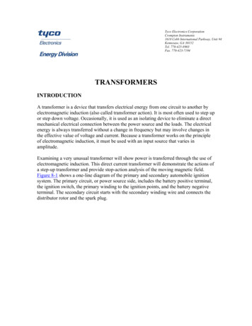
Phase Shifting Transformer PictureCosts about 7 million,weighs about 1.2million pounds230 kV 800 MVA Phase ShiftingTransformer During factory testingSource: Tom Ernst, Minnesota Power51
Power Transformers from China
Autotransformers Autotransformers are transformers inwhich the primary and secondarywindings are coupled magneticallyand electrically. This results in lower cost, and smallersize and weight. The key disadvantage is loss ofelectrical isolation between thevoltage levels. This can be animportant safety consideration whena is large. For example in steppingdown 7160/240 V we do not everwant 7160 on the low side!54
transformer equation. In modern power transformer of large kVA ratings, the magnetizing currents in their normal operating region are very small, for example, well below 0.2% of the rated current at the rated voltage.