Transcription
8. TESTING POWER TRANSFORMERSHigh-voltage transformers are some of the most important (and expensive) pieces ofequipment required for operating a power system. The purchase, preparation, assembly,operation and maintenance of transformers represent a large expense to the powersystem.8.1OVERVIEWWhen transformers are received from the factory or reallocated from another location it isnecessary to verify that each transformer is dry, no damage has occurred during shipping,internal connections have not been loosened, the transformer’s ratio, polarity, andimpedance agree with its nameplate, its major insulation structure is intact, wiringinsulation has not been bridged, and the transformer is ready for service.Physical size, voltage class, and kVA rating are the major factors that dictate the amountof preparation required to put transformers in service. Size and kVA rating also dictatethe kind and number of auxiliary devices a transformer will require. All of these factorsaffect the amount of testing necessary to certify that a transformer is ready to beenergized and placed in service.There are a multitude of checks and tests performed as a transformer is being assembledat a substation. The test engineer may not directly perform all of the following tests andinspections but must be sure they are satisfactorily completed, so that the final decisionover transformer bank readiness for energization can be made.Some tests and procedures may be performed by specialists during the assembly phase.Special tests, other than those listed, may also be required. Many require specialequipment and expertise that construction electricians do not have and are not expected toprovide. Some tests are performed by an assembly crew, while other tests are done bythe person(s) making the final electrical tests on the transformers.BPA has hundreds of power transformers installed throughout the system, and few ofthem are identical. The following information is not intended to describe, or include, thedetails for performing the entire array of tests needed to prepare transformers for service,only the tests that may be performed by field personnel. Even though details have beenlimited, descriptions should allow field personnel to perform, or assist in performing, thebasic tests they may be asked to do. Procedures and tests are described somewhatgenerically, but apply to most transformers in one way or another. Also, the followingtest descriptions provide an anchor point from which to ask for help when needed. Thefollowing items are discussed or described: Nameplate Data Auxiliary Components and Wire Checks Hand Meggering Power Meggering Lightning Arrestors Temperature Devices
CT TestsBushing Power FactoringTransformer Power FactoringVoltage RatioPolarityTransformer-Turns RatioTap ChangersShort-Circuit ImpedanceZero SequenceWinding Resistance Winding Temperature and Thermal ImageRemote Temperature IndicationAuxiliary PowerAutomatic Transfer SwitchCooling SystemBushing Potential DeviceAuxiliary-Equipment Protection and AlarmsOverall LoadingTrip ChecksBefore proceding with transformer measurements the test engineer will become familiarwith the safety rules of Section 2. THESE RULES MUST BE FOLLOWED FORALL TEST PROCEDURES. Following is an approximate sequence for transformertesting:1. Inspect transformer and parts for shipping damage and moisture.2. Check nameplate and prints for proper voltages and external phasingconnection to the line or bus.3. Check calibration of all thermal gauges and hot-spot heater, bridge RTDs andassociated alarm contacts. Contact settings should be similar to the following: One stage runs all the time (forced cooling)2nd stage at 80 C3rd stage at 90 CHot-spot alarm 100 C (trip at 110 C when applicable)Top-oil alarm 80 C at 55 C rise and 75 C at 65 C riseOA no fans or pumpsFA fans runningFOA fans and pumps running4. Check and Megger all wiring point to point: Fans, pumps, alarms, heaters, tapchangers, and all other devices on the transformer and interconnecting cables5. All banks above 150 MVA should be vacuum dried. Do not apply test voltagesto the winding during the vacuum drying process. Make certain the terminalsare shorted and grounded during oil circulation because of the large amount ofstatic charge that can build up on the winding.6. After the tank has been filled with oil, confirm that an oil sample was sent tothe Chemical Lab and that its results are entered in the bank test reports. Notethe oil level and temperature at completion of filling.7. Power operate to verify proper rotation of pumps and fans and correctoperation of the under load (UL) tap changer, when provided. Also, checkheater, alarms and all other devices for proper operation.12. Following are the winding tests to be performed:
Ratio and Polarity (Voltage Method or TTR). The preference is that all largepower Transformers ( 1 MVA) be tested with TTR test set.ImpedanceDC winding resistanceMegger and Power Factor windings, bushing and arrestors. Note: Wait until 24hours after completion of oil filling for Power Factor testing.13. Load CT circuits overall and flash for polarity.14. Before energization, trip-check bank protection schemes and make sure the gascollection relay is free of gas.15. When energizing a bank or picking up load, monitor bank currents and voltages,including UL tap-changer operation.16. Check proper phasing and voltage of the bank to the system before load ispicked up. When possible, large transformers ( 1 MVA) should remainenergized for eight hours before carrying load.17. Make in-service checks on meters and relays.18. Release to Operations and report energization information to the TNE office.19. Turn in revised prints and test reports, which should include the following: 8.2All test dataMoisture and oil dataProblems incurredIn-service dataTime energized and release to operationAny unusual problem that information will aid in future equipment testingNAMEPLATE DATA and TERMINAL MARKINGSCollecting nameplate data is not testing, but it must be done for all equipment. Thisdata is recorded by the person(s) performing the equipment tests. The act of recordingthe nameplate data also helps test personnel familiarize themselves with the unit to betested.For a transformer, much of the needed information can be obtained from the mainnameplate. If there is an under load tap changer, it too will have a nameplate. CTs havename plates and may have them on the bushing pockets where they are mounted withadditional information on a nameplate placed inside the cooler-control cabinet door(typical on large transformers). Bushings, fuses, fan and pump motors, lightningarrestors, and disconnect switches will also have individual nameplates. An attemptshould be made to fill in all pertinent spaces on the data sheet. A miscellaneousinformation space is provided on data sheets for information that pertains to thetransformer but does not have a specified place to record it. Recording miscellaneousinformation not identified specifically by a test data sheet may be important as well.
Terminal marking of power transformers is determined by ANSI standards. Twowinding transformers have terminals designated by H and X (e.g. H1, H2, X1, X2,), whereH is the higher voltage-rated winding and X is the lower voltage winding. As viewedfrom the high-voltage side, H1 bushing terminal will be located on the right. Three-ormore-winding transformers will have winding designation H, X, Y and Z, where H is thehigh-voltage winding (or, the highest kVA-rated winding in case windings have the samevoltage rating) and X, Y, and Z are for decreasing winding voltage ratings.8.3 AUXILIARY COMPONENTS AND WIRE CHECKINGThe size, type, and location of a transformer dictate the amount of external equipmentassociated with it. A transformer may be outfitted with devices that are not to be used atthe time of installation. Even if not expected to be placed in service, all auxiliaryequipment should be checked for proper operation to assure it is not defective and couldbe utilized in the future if needed. This is especially true for a new transformer, in orderto verify that what has been received is fully functional.All wiring on the transformer should be checked and verified prior to energization.Check control panels, terminal cabinets, and cables routed to the transformer. Torque allscrew, nut, and bolt terminals for tightness, including the wires on CTs where theyoriginate at the connection boxes on the high-voltage bushings. If there is an UL tapchanger, its wiring must also be checked.Wire checking a transformer’s auxiliary equipment is useful for several reasons. Athorough check might prevent damage or destruction of a unit that is difficult, expensive,or impossible to replace. This process also provides personnel an opportunity to becomefamiliar with the equipment. A thorough wiring check forces personnel to look at theequipment in detail, serves as a cross check for drawings, and verifies that documentationand prints actually represent the physical equipment. It helps assure that wires andcomponents are properly sized, secure, and ready for service.8.4 HAND MEGGERING (DC Hi-Potential Insulation Testing)Most hand-crank Meggers have output voltages from 250 to 500 volts DC. All wiring ontransformers should be Meggered at 250 or 500 VDC.Meggering transformer wiring is emphasized because of the numerous small terminalboxes mounted on large power transformers. Conduit connecting them together can havemoisture accumulation or water leaks. In addition, when wiring is pulled through themetal conduit on a transformer, occasionally the insulation is scraped down to the barewire.Also note that any box mounted on a vertical surface should have a small drain holedrilled at the bottom in case water leaks in from a loose conduit joint. Larger boxes orcabinets usually have resistive heaters and air-vent holes covered by screens to prevent
moisture accumulation. Terminal boxes mounted on horizontal surfaces must have goodweather seals for their covers. Any gasket with questionable ability to provide awatertight seal should be replaced.Early completion of wire checking and low-voltage-component meggering is advisable,especially when large transformers are to be tested. Completion of these tasks up front isimportant because it allows application of power to alarm and control circuits withoutworry of causing damage. Having auxiliary power available helps facilitate operationalchecks, especially when UL tap changers need to be operated to perform various tests.Changing tap positions manually by hand cranking the mechanism is a slow and tiresomeprocess.8.5 CT TESTSTransformer bushing CTs should be tested using the Current Ratio test method before thetransformer has been completely assembled. CTs should be tested before they aremounted on the transformer. In some cases, CTs may have to be tested by connectingtest leads to both ends of an installed bushing. This can be difficult! If the CTs arealready mounted in the transformer, large (high-capacity) current-testing leads can bepulled through the CT centers before bushings have been inserted.Occasionally it is not possible to perform a Current Ratio test. CT tap ratios can beverified by applying a voltage across the full CT winding – a Tap Voltage Ratio test -then measuring the voltage drop across each individual tap. This is a simple test toperform, and voltage ratios will be directly proportional to the CT turns ratio betweentaps.This Tap Voltage Ratio test, however, should not be chosen as a substitute for a CurrentRatio test. The voltage method should be regarded as the last alternative. Testing theequipment at rated current offers more assurance that it will perform as expected whenplaced in service. The Current Ratio method reflects this philosophy; the Tap VoltageRatio method does not. The Tap Voltage method cannot establish true orientation(polarity) of the installed CT, or test the primary to secondary current ratio, and leavessome points unverified.In addition to Tap Voltage Ratio, a secondary Tap Current Ratio test can be performed.For this test, rated or less current is injected through a tap input and the output current ofthe full CT winding is measured by transformer action. It is equivalent to the procedureused for performing a Short-Circuit Impedance test on an autotransformer.CT POLARITYIt is still necessary to verify CT polarity. One method used to establish CT polarity inpower transformers is commonly referred to as "Flashing the CTs." This test can beperformed by applying 6-to-12 volts DC to the transformer bushings, using a hot stick tomake and break the test circuit. An automobile battery is often most convenient because
work vehicles are usually available at the job site, but a lantern battery will work as well.The transformer winding resistance is usually enough to limit the current flow from a 12volt car battery, but adding series (current-limiting) resistance (a load box) to the testcircuit is advisable in any test circuit with an automotive battery.Be aware that the DC test circuit will generate a voltage kick when disconnected. Takeprecautions to prevent electric shock. If performing this test directly on CTs, alwaysinclude a current-limiting resistance (a load box) in the flash lead connections. Lanternbatteries have high internal resistance and don’t need an extra series resistor. Arc flash ona power transformer can be limited if the transformer windings are short circuited on theside opposite those being flashed through.WARNING!A transformer winding that is carrying DC current will generate a large voltageacross the winding when disconnected. To prevent electric shock, use a means ofinsulation from the connection when breaking the test connection. A hot-stick toolis recommended.WARNING!When using lead-acid car batteries never make or break circuit connections on abattery terminal. Lead-acid batteries produce hydrogen gas when charging andhave been known to explode if ignited by an electric spark when connecting directlyto both battery terminals.To make a test circuit for flashing a CT, connect battery positive (the positive terminal ofa car battery) to the polarity end, or high-voltage terminal, of the transformer. Add seriesresistance, such as a resistive load box, into the test circuit to limit short-circuit current.Current-limiting the short-circuit DC test current can reduce core magnetization.Connect battery negative (car chassis or frame ground) to the test lead used with a hotstick tool. The hot-stick lead is used to touch the nonpolarity end of the bushing orstation ground if a grounded transformer is being tested. Current must be allowed to flowthrough the bushings and CTs long enough to build up a charge in the transformerwindings. A hot stick is required to make and break this charging path because anextremely large arc can be generated as the magnetic field collapses. An analogvoltmeter (such as a Simpson VOM) is connected across the CT secondary terminals withthe meter polarity side referenced to CT polarity (X1). While this charge and dischargeof the windings is initiated, an observer can also watch for buildup and collapse of the CTsecondary current on a low-scale ammeter plugged into an appropriate set of relays orammeters. The test meters deflect upscale on charge and downscale on discharge, if theCT polarity is correct. Begin the test by momentarily touching the bushing cap (orground connection) with battery negative for one or two seconds. Increase the DCapplication time as needed to get enough meter deflection to assure results. If thetransformer requires some time to build a charge in its windings, there may not be verymuch positive deflection on contact, whereas there may be a much greater negativedeflection on break.
For CT accuracy and performance, flashing may not be a desirable test to performbecause a condition of residual magnetism in the CT core can result. In theory, a possibleconsequence could be an improper relay operation due to CT saturation upon initialenergization. If possible, demagnetizing the core is advisable after a DC flash test usinghigh current. Residual flux is removed by gradually applying AC test current (excitationcurrent) to the high-current primary, or AC test voltage to the low-current secondary(excitation voltage), and forcing the CT just into saturation with the secondary opencircuited. After slowly reducing the AC quantity from saturation point to zero, residualflux will be removed from the core (it will be demagnetized).8.6BUSHING POWER FACTORING (AC Hi-Potential Insulation Testing)All bushings should be power factored before they are inserted into the transformer. If aPower Factor set is not available when a new transformer is being assembled, acapacitance bridge should, at the very least, be used to measure the bushing tapcapacitance values. Measure the values for both C1 and C2 (especially if they arespecified on the bushing nameplate). A proper capacitance test could indicate whether aserious internal problem with a bushing exists prior to insertion and whether a powerfactor test would be advisable.Megger the bushing and its tap at 2500 volts if no Power Factor set is available.CAUTION!Check the bushing tap insulation rating before applying 2500 volts; small bushings maybe able to withstand no more than 500 or 1000 volts at the tap.8.7 TRANSFORMER POWER FACTORING (AC Hi-Potential InsulationTesting)The transformer itself should be power factored soon after the drying process is completeand the tank is filled with oil. All bushings should again be power factored at this timebecause their readings will change slightly after assembly. A complete set of PowerFactor data should include winding-to-winding, winding-to-ground, and bushing tests. Ifa 10-kV power factor set is available, a Winding Excitation test should be performed. AWinding Excitation test on very large transformers may not be possible due toinsufficient capacity of the Power Factor set for supplying required excitation current.8.8SINGLE-PHASE VOLTAGE RATIO, POLARITY and IMPEDANCEMEASUREMENTSRatio, polarity, and impedance measurements are compared with nameplate data to verifytheir correctness and to ensure that there is no hidden shipping damage, that the
transformer field assembly is correct, and that the transformer is ready for service. Inaddition, these test data reports become a valuable tool when compared with laterdiagnostic tests used to assess transformer condition.Single-phase test procedures can be used to measure the ratio and impedance oftwo-winding transformers, three-winding transformers, autotransformers, andthree-phase transformers. Moreover, in the case of three-phase transformers (with aWye connection) and grounding banks, zero-sequence impedance measurements aremade with the single-phase procedure. Comparisons between measurements are usefulwhen single-phase tests are made on three identical transformers or on each phase of athree-phase transformer, as it is unlikely that each single-phase unit or each phase of athree-phase transformer would have sustained the same damage.SafetyBefore proceeding with any measurements in a high-voltage substation, the test engineermust be thoroughly familiar with the job. Make sure the transformer bank being tested isde-energized, out of service, and isolated from the power system before climbing on it orconnecting it to any test leads.Follow all safety rules and be aware of any energized equipment in the working area.Never uncoil test leads by throwing them in energized yards. Ground test equipment andtest circuits to avoid stray voltages from energized lines, lightning or close-in faults. Takecare to check the polarity of the test voltage. The grounded leg of the 115-VAC sourceshall be connected to ground for safety.WARNING!Extreme caution must be observed when test-energizing high-ratio transformers (10to 1, for example), because high voltages will be present at the transformerterminals. Care must be taken not to energize bus or equipment that electricians orother personnel could be working on and that test equipment does not contactenergized equipment.If equipment terminals are accessible or if the bus is connected to the transformerterminals, conceivably transferring test potentials to other locations, fence off theexposed areas with guards as required by safety procedures, warn working personnel oftest-energized potentials, and if necessary provide a Safety Watcher. If possible, ratio testtransformers before terminal connections to buses have been made.8.8.1 SINGLE-PHASE POLARITYThe polarity designation of each transformer winding is determined by the relativedirection of instantaneous current or voltage as seen at the transformer terminals. Forexample, primary and secondary leads are said to have the same polarity when, at a giveninstant, current enters the primary lead in question, the instantaneous induced voltage inthe secondary is increasing when the impressed voltage on the primary is increasing, orconversely, if they are both decreasing at the same instant.
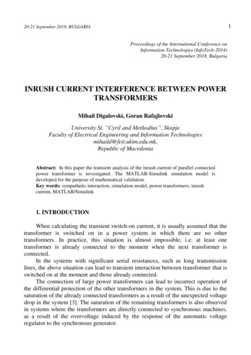
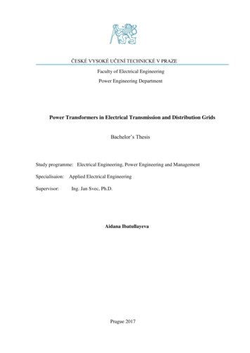
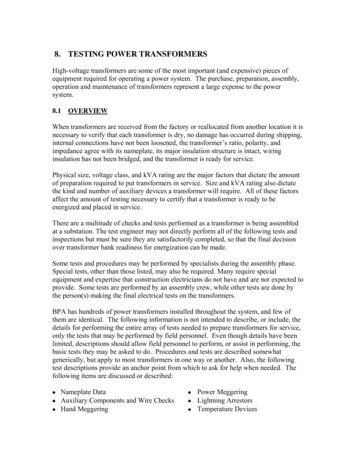
Figure 47: Single-Phase Transformer PolaritiesA. SubtractiveB. AdditiveTransformer polarity relates to how winding leads are brought out to bushing terminals.These connections are determined by transformer design, winding directions and internallead clearance requirements. Transformer polarity is either subtractive or additive. If theinstantaneous polarity (as defined above) of adjacent terminals is the same, transformerpolarity is subtractive (See Fig. 47A). If diagonally opposite terminals of a transformerhave the same instantaneous polarity, transformer polarity is additive (See Fig. 47B).Transformer winding polarity locations are important when identical windings on atransformer are to be paralleled, when paralleling transformers with identical ratios andvoltage ratings, when determining three-phase connections of transformers, and toestablish the correct connections for three-phase transformers that operate in parallel withthe power system. Polarity between transformer windings may be determined either bycomparison with a transformer of known polarity, DC flashing or the AC method. Onlythe latter two methods are used by TNE.8.8.2 TRANSFORMER POLARITY BY DC FLASHING METHODThe DC Flashing test uses 1.5-V to 6-V dry-cell batteries and a DC voltmeter with 1.5-Vto 10-V scales. Meter deflection directions will be more discernible if the meter’smechanical zero position can be adjusted in an upscale direction to allow deflecting inboth directions. As shown in Fig. 48, the test is conducted by connecting the voltmeter tothe transformer low-voltage terminals and connecting the battery intermittently to thehigh-voltage winding.Figure 48: Polarity Test by DC Flashing
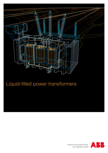
In Fig. 48, transformer polarity is subtractive if the meter shows an upscale kick whentest connection SW is closed and a downscale kick when test connection SW is opened.In this case bushings “A and B” would be labeled “X1 and X2,” respectively as polarityterminals are adjacent. Transformer polarity would be additive if the meter shows adownscale kick when test connection SW is closed and upscale kick when test connectionSW is opened. In this case bushings “A and B” would be labeled “X2 and X1,”respectively as polarity terminals are diagonally opposite.Note: The inductive kick when the battery circuit is opened will be much larger thanwhen the battery circuit is closed.Adequate meter deflection will require a dry-cell battery that is in good condition, lowresistance connections to bushing terminals, and positive make-and-break connections toterminal H1. The usual procedure is for the person operating the battery connections tosay, “Make” when connecting the positive battery terminal to the H1 bushing and “Break”when opening the connection. Then, observation of meter deflections determinestransformer-winding polarity. Also, verify meter terminal markings by measuring a drycell prior to testing.WARNING!Do not become in series with the test leads by holding the battery clip lead in onehand while also hand contacting the H1 terminal.8.8.3 POLARITY TEST BY THE AC METHODIf the AC method is used to determine winding polarity, a voltage may be applied to thehigh-voltage winding (H1 to H2) and the two adjacent bushings of the high- and lowvoltage windings (H2 to B) are jumpered together (Refer to Fig. 49, below).
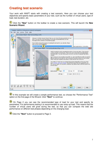
Figure 49: AC Method for Testing Transformer PolaritiesFor the voltmeter, when VPOL VH - VX the transformer functions with subtractivepolarity and terminals A and B would be labeled “X1 to X2,” respectively. Conversely,when VPOL VH VX the transformer has additive polarity and terminals B and A wouldbe labeled “X1 to X2,” respectively as polarity terminals are diagonally opposite eachother.The AC Polarity test method can be conveniently made during the Transformer Ratiotest. The methodology used to check ratio include the Voltage method and theTransformer Turns Ratio (TTR) test set. The test is used to check nameplate voltagevalues for the range of taps on the transformer.8.8.4 RATIO AND POLARITY VOLTMETER TEST OF TWO-WINDINGTRANSFORMERSThe circuit for making ratio and polarity tests of a two-winding transformer is shown inFig. 50.
Figure 50: Ratio and Polarity Voltmeter Method For Two-Winding TransformersIt consists of the 115-VAC source, a 10-A fused switch, a variable autotransformer(Variac), an ammeter and three voltmeters. A ratio measurement accuracy of 1% wouldrequire 0.5%- accuracy voltmeters or 4 ½-digit digital voltmeters. Measurement accuracycan be improved by having a stable sinusoidal voltage regulator ahead of the variableautotransformer. Test voltages used to determine high-voltage power transformer ratiosare usually 1/1000 of the winding’s rated voltage or less to reduce testing hazards. Thesimplest test values to choose are those for which a decimal point reading would read thesame as high- and low-winding nameplate kV values. The test voltages read are in volts,but read directly as if they were in kV. For example, if the nameplate says the voltage ona particular tap should be 112,750 volts to 13,800 volts, energize the high-voltagewinding at 112.75 volts and expect to read 13.80 volts on the low side. Digital meterswith four- or five-place accuracy are needed to make readings this exact. Measurementsshould be recorded for every tap-changer position.Test evaluations are aided by pre-calculating the expected test voltages and filling out thedata sheets ahead of time.In making voltage measurements, separate voltmeter leads connected directly to bushingterminals must be used to avoid errors due to voltage drop in the source leads. Theammeter should be included in the test setup to monitor input current to the transformerin case the current is high due to a short circuit, shorted turn, or other connectionproblems.Because induced voltage from nearby current-carrying bus or lines could modifymeasurements, make low-resistance connections directly to transformer bushing
terminals and don’t coil up excess potential lead length; lay excessive leads side by side,oriented at 90 with induction sources.The lower voltage winding should be excited, in most cases, to some multiple of itsrating. For example, if the transformer in Fig. 50 is rated 115.5 kV to 7.2 kV, energize thelow-voltage winding to 7.2 V, then measure voltage on the high-voltage winding. Thehigh side should be 1/1000 of its rating, or 115.5 V. The voltmeter, VPOL, will read thedifference -- 108.3 V -- for subtractive transformers.If the high side has a tap changer, hold the 7.2 V constant on the low-voltage winding andread the new high-side voltage for each tap position. These voltages may be compareddirectly with the nameplate values.WARNING!Remember, if transformer terminals are accessible or if bussing is connected to thetransformer terminals, all safety procedures of this transformer section as well asSection 2 must be followed.8.8.5 MEASUREMENTS FOR SINGLE-PHASE THREE-WINDINGTRANSFORMERSDiagnostic tests of single-phase three-winding transformers are made with theprocedures described above for single-phase two-winding transformers. Ratio, polarityand impedance measurements are made between winding pairs, i.e., high-to-low-, highto-medium- and medium-to-low-voltage windings, as shown below (See Fig. 51).
Figure 51: Single-Phase Ratio and Polarity Test of Three-Winding TransformersRatio and Polarity Measurements1. High to Low: Excite the low-voltage winding, Y1 to Y2 EL. When the lowvoltage windings have additional taps (Y1, Y2, Y3, Y4), measure all taps on lowvoltage winding. (Example: Y1, to Y2, Y1to Y3, Y1to Y4). Measure high-side (H1to
H0) voltage throughout its tap-changer range, EH. Ratio EH/EL.2. Medium to Low: Excite low voltage winding, Y1to Y2 EL. Measure mediumvoltage, XH to X2/X0, throughout its tap-changer range, EM. Ratio EM/EL3. High to Medium: Excite medium-voltage winding, X1 to X2/X0 EM. Setmedium winding on nominal tap, measure high-voltage winding, H1to H2, EHthroughout its tap-changer range, EH. Ratio EH/EM. In case of auto banks, gethigh winding on nominal and measure voltage throughout medium tap-changerrange.8.8.6RATIO AND POLARITY – TTR METHODThe Transformer Turns Ratio (TTR) method compares the test transformer ratio with anadjustable-ratio standard transformer by using a null balance detector to determine whenthe standard transformer ratio is the same as the test transformer. During test procedurestransformer polarity is determined by comparison with the standard transformer (See Fig.52, below).Figure 52: TTR Method for Testing the Transformer Turns Ratio
A TTR test should be made for any new high-voltage power transformer at the time it isbeing installed. This test is also desirable for any transformer that has
Terminal marking of power transformers is determined by ANSI standards. Two-winding transformers have terminals designated by H and X (e.g. H 1, H 2, X 1, X 2,), where H is the higher