Transcription
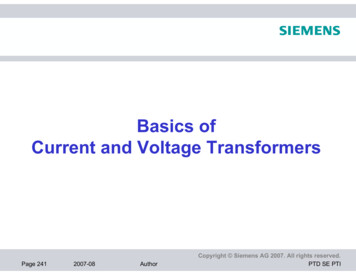
Power Transformers Basics
Transformer Basic Objective Introduce Basic Transformer Theory as itRelates to Diagnostics Provide a Better Understanding of theDiagnostic Test Environment Identify Important Information that should becollected in the Diagnostic Test Process
Topics of Discussion Definition Transformer Types and Classifications Transformer Configurations Vector Groups Life Expectance Oil Preservation Systems Insulating Materials and Fluids Construction Forms Core Steel Nameplates Ratings Cooling Schemes Tap Changers (OLTC, DETC)
Transformer Categories Insulation System- Construction- Liquid ImmersedDry TypeGas FilledTank TypeCore Type / Shell Type1 Phase / 3 PhaseDouble-Wound, Multi-Winding, AutoWinding Configuration and TypeApplication
Transformer Types and Classifications Distribution Power Rectifier Arc-Furnace Network Regulating (Voltage Regulators) Phase Shifting Reactors*
Transformer Classifications Distribution Rated 500 kVA and BelowUp to 34.5 kVStep-down ApplicationUsed in Customer CircuitPower Rated 500 kVA and AboveBetween Generation and DistributionGSU Generator Step-Up, Autos, TransmissionClass XFMRsAutotransformers
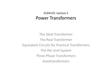
Winding Configurations Delta Wye Auto Zig-Zag
Vector Groups
Vector Groups
Vector Groups – Head to Tail RelationshipPhase APhase BPhase CHVH1-H3H2-H1H3-H2LVX1-X0X2-X0X3-X0
Life Expectancy of Transformer Insulation 180,000 hrs or 20.55 years 110 C Hottest Spot for 65 C Temp Rise insulation Degree of Polymerization (200 -1200 DP) 1200 DP - New Paper 200 DP at 150,000 hrs (end of life) Heat Moisture Oxygen
Insulating Materials and Fluids Oil MineralSiliconeAskeral – Polychlorinated Biphenyls (PCB)Natural and Synthetic EstersHigh Molecular Weight HydrocarbonsSyntheticPaper (cellulose) wood fibermanila rope Pressboard (wood fiber and cotton) Resin Varnish
Oil Most insulating fluids have very good properties,however the unique characteristics and attributes of eachproduct must be considered when selecting an insulatingfluid for a specific application. Purposea. Dielectric Withstandb. Heat Exchange (Cooling)c. Arc Mitigation
Winding Types1. Disk Winding2. Pancake Winding3. Helical Winding4. Cylindrical or Layer Winding
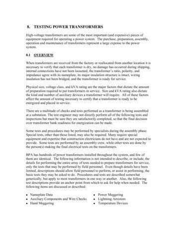
Disk Winding Each disk is wound in series Disks are stacked in parallel Uses crossovers (inner-outer) Used mostly in 34.5 kVand above core typesCourtesy of Delta Star, San Carlos, CA
Disk Winding “Crossover” Close-upCourtesy of Delta Star, San Carlos, CA
Disk Winding – Autotransformer Common WindingCourtesy of Delta Star, San Carlos, CA
Pancake Winding Used in Shell-Type Transformers Stacked by Interleaved SchemeCourtesy of ABB TRES - ABB Inc., Saint Louis, MO
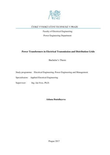
Helical Winding Strands wound in parallel High-Current Low VoltageLow-Voltage WindingCourtesy of Delta Star, San Carlos, CA
Helical Winding – Low Voltage WindingCourtesy of Delta Star, San Carlos, CA
Layer or Barrel WindingRegulating Winding Conductors wound side by side Layers can be woundon top each other Regulating Windings Tertiary WindingsCourtesy of Delta Star, San Carlos, CA
Oil Preservation Systems Free Breathing Conservator Sealed - Air/Gas Headspace Pressurized Nitrogen Conservator with Bladder
Free Breathing Conservator Oil is exposed to air in the conservator Only a small portion of the oil is exposed to air
Sealed – Air/Gas Headspace Operates at /- 5 psi differential to atmosphere Always verify pressure before sampling
Pressurized Nitrogen Blanket Maintains positive pressure Purges nitrogen 5 psi Always verify pressure before sampling
Conservator with Bladder Oil is isolated from atmosphere Operates at atmospheric pressure
Construction FormsCore FormShell Form Concentric Interleaved Less Iron More Iron More CU Less CUCore FormShell Form
Core Steel Goal – Minimize cost of ownership by minimizing losses Constructed from steel sheets (0.25 mm) that has acoating (insulation); stacked laminations Eddy Losses – Proportional to the sheet thickness Hysteresis Losses – Influenced by the metallurgicalrecipe and process Grain Oriented – Align magnetic domains for the bestperformance in plane of intended flux paths.
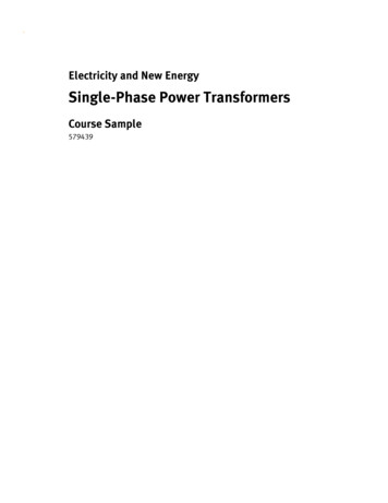
Nameplates Identification: Manufacturer, Year, Serial Number Ratings-MVA, kV, BIL, Amperes, %Z p.u.Cooling ClassInsulation Temperature Rise Vector Diagram Wiring Diagram Weights and Volumes OLTC, DETC Rating and Connection Mapping
Nameplate Drawing
Ratings
Vector Diagram
Wiring Diagram
Weights and Volumes
DETC Information
OLTC Information
Fault Protection1. Pressure Relief Valves2. Sudden Pressure Relay3. Buchholtz Relay Sudden Pressure RelayGas Accumulation RelayOnly Applied to Conservator Systems
Cooling Prevent damage and loss of life to the insulation system Ages paper, pressboard, and oil Natural Convection Fans Pumps Water Directed Flow
Pumps, Fans, Radiators
Temperatures Top Oil Bottom Oil Average Oil Average Winding Hot Spot
Cooling Schemes – IEEE OLD OA Oil-Immersed Self Cooled FA Oil-Immersed Forced Air FOA Oil-Immersed Forced Oil / Forced Air OW Oil-Immersed Water Cooled FOW Oil-Immersed Forced Oil / Forced Water OW/A Oil-Immersed Water Cooled / Self Cooled FOA* Oil-Immersed Forced Oil Directed / Flow Forced Air FOW* Oil-Immersed Forced Oil Directed / Flow Forced Water Indicates directed oil flow
Cooling Schemes – IEEE/IEC New ONAN Oil Natural / Air Natural ONAF Oil Natural /Air Forced OFAF Oil Forced /Air Forced OFWF Oil Forced / Water Forced ODAF Oil Forced-Directed / Air Forced ODWF Oil Forced-Directed / Water Forced
Cooling Schemes – Conversion ONAN OA ONAF FA OFAF FOA OFWF FOW ODAF FOA ODWF FOW Indicates directed oil flow
OLTC North America – Low Side Application Often 33 position Often /- 10% Regulation 16R, 15R, .1R, N, 1L, .15L, 16L Reversing Switch
Tap ChangersDETC
DETC NOT to be operated in service (See #3 below) Follow local policies regarding movement Often 5 positions [1, 2, 3, 4, 5] [A, B, C, D, E]
Active LTC Diagnostics Exciting Currents Turns Ratio DC Winding Resistance, Slope, Ripple DGA IR Acoustics
Thank You for Your Attention OMICRON
Transformer Classifications Distribution Rated 500 kVA and Below Up to 34.5 kV Step-down Application Used in Customer Circuit Power Rated 500 kVA and Above Between Generation and Distribution GSU Generator Step-Up, Autos, Transmission Class XFMRs Autotransformers