Transcription
Power Calculation 2Design Studies
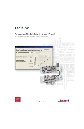
Compressor Design (Example 5):Specifications: 35cfm free air delivered. Output pressure 6.895 Bar.Intake air 0.97 Bar 27 C(Assume there is an intake pressure drop and intake air has been‘warmed’ up by the hot cylinder)Driven at 500 rev/minClearance 5% of the swept volumePolytropic index n 1.3Bore-stroke ratio: 2:3Free air delivered conditions:15 C and pressure 1.013BarR 287Compressor mechanical efficiency ηc 80%Motor and transmission efficiency ηd 85%Design a single cylinder, single-acting reciprocating compressorDesign Studies
Design Studies
Solution:Free air delivered per minV fad 35 0.028317 0.9911m 3 / min ,(1 cube foot 0.028317 m 3 )Free air delivered per cycleV free V fad / 500 0.0020 m 3 / cycleEffective Swept volume:V1 V4 p freeV freeT1T free p1 1.013 0.0020 ( 273 27 ) 0.0022 m 3( 273 15) 0.97(A)Expanded clearance air volume:1/ n p V4 V3 3 p4 1 / 1 .3 1.013 V3 0.97 4.5232V3(B)Clearance 5% of swept volume:V3 0.05(V1 V3 )(C )From simultaneous Eqs (A), (B) and (C), findV1 0.0027 ,V3 0.000131,V4 0.000592 m 3Design Studies
Calculate cylinder sizes:πb 2 sπb 2 ( 3 / 2 ) b V1 V3or V1 V344bore : b 0.1305 mstroke : s 0.1957 mCompressed air temperature p T2 T1 2 p1 n 1n 6 .9 ( 273 27 ) 0.97 1.3 11 .3 471 .7963 KFree air mass densityρ p freeRT free1.013 10 5 1.2256 kg / m 3287 ( 273 15)Power absorbed by the free air delivered (energy per second)nnm& R (T2 T1 ) V free ρR (T2 T1 )n 1n 15001 .3 0.0020 1.2256 287 ( 471 .8 300 ) 4.3253 KW1 .3 160W Design Studies
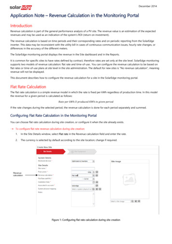
Motor power required:W4.3253Wm 6.361 KW0.80 0.85η cη dorWm 6.361 / 0.7457 8.53hpCompressed air volumeP1V1 T2 0.000608T1 P2p-V chart can be plotted (see next page)V2 Volumetric efficiencyηv V freeswept volume V freeV1 V3 75 .73 %Compressor indicated power ( by the free air delivered per unit time)n 1 n npWindicated p1 (V1 V4 ) 2 1 f 4.3253 KW p1 n 1 where f – cycles/sDesign Studies
Design Studies
Compressor design considerationsCapacityUnusual operating conditions may require a larger unit than indicated. If you are notcertain, select a larger unit to ensure adequate initial capacity and provide for futureneeds.Compressor IntakeIt is important to provide fresh, uncontaminated air to the compressor's intake sincegross contamination of intake air will adversely affect the efficiency of the purifier. Ifthe compressor is operated near running vehicles or close to a gas heater, the CO andCO2 levels in the ambient air may be affected resulting in an adverse impact on the airquality of your system. If the compressor is located in a room where chemicals arestored, fumes or particles from the chemicals can be drawn into the system and affectair quality. Your compressor should never be located where volatile gases can enter thecompressor.To safeguard your system's air quality, a remote intake may need to be installed inanother room, on an outside wall, or on the roof. A drip leg with drain should beprovided to prevent water from entering the compressor intake.Design Studies
Flow Requirements1.The time required to fill the stack.2.The capacity of your storage system.Flow RateA compressor has two ratings for delivered flow rate: free air delivery (FAD) and averagecylinder charge rate (CR). When the same compressor is rated using these two methods,the results are dramatically different - average charge rate will exceed free air delivery.Free Air DeliveryFree air delivery (FAD) measures the compressor's output at a specific operating pressure.The result, normally expressed in actual cubic feet per minute, rates the outlet flow basedon inlet conditions. This method for measuring FAD is specified by the American Societyof Mechanical Engineers (ASME PTC-9) and the International Standards Association(ISO 1217).Design Studies
Cylinder Charging RateCharging rate measures the average output of a compressor as it fills a BA cylinder. Sincethere are no recognized standards governing how a charging rate is determined, the methodof determining the rate is left up to the individual compressor manufacturer. As a result,there are numerous ways to calculate a charging rate. The rate is usually obtained by timinghow long it takes a compressor to fill a BA cylinder, perhaps an 80 cf SCUBA cylinder,from 0 to 3000 psig. The cylinder volume (80cf) is then divided by the filling time (5minutes, for example). The result would be a charging rate of 16 cfm.For the purposes of this document, both FAD and CR ratings are referenced. However, allcylinder refill system calculations utilize FAD.Design Studies
Pressure RequirementsChoose a compressor that is rated at a higher operating pressure than is needed to complete yourcylinder refill requirements. Higher operating pressures aid in the purification process as well asmaking it possible to store a greater volume of air in the same physical space.Multiple Stage CompressorsMultiple stage reciprocating compressors are utilized to produce high pressure air. High pressurecompressors are available in a number of configurations employing either a lubricated or a nonlubricated design. The basic difference is the presence of lubricant within the compression process.Non-lubricated compressors are designed with closer tolerances within the compressor's valveassemblies and cylinder walls. When compared to a lubricated compressor, the non-lubricatedcompressor will also require more frequent service intervals.Lubricating oil is viewed as a contaminant, but it also serves many critical functions. Lubricatingoil reduces the operating temperature of the compressor, reduces friction (thus increasingcompressor operating efficiency and output), minimizes air leakage around piston rings, and itreduces the possibility of internal corrosion. Lubricating oil will also assist in the removal of dirt,wear particles and liquid water within the compressor.Design Studies
Compressor Components and ControlsIt is highly recommended that a compressor be equipped with automatic controls to preventdamage due to human error or mechanical failure. Magnetic starter (with overload protection) Belt guard (OSHA requirement) Intake filter Inter-stage coolers After coolers Pressure safety relief valve for each stage of compression Elapsed time recorder Condensate drain traps High temperature alarm and/or carbon monoxide alarm when using an oil-lubricated compressor(OSHA requirement).Design Studies
Advanced Monitoring and ControlMore automated with more elaborate controls and sophisticated components.Examples include: Automatic condensate drain with muffler/reservoir assembly Low oil level alarm and/or shutdown Inter and final stage pressure gauges Emergency stop and restart controlsProgrammable Condition Monitoring and ControlWith the advent of automated compressors, programmable controls have begun toreplace electro-mechanical designs of the past. A programmable electronic controlsystem will provide an operator with numerous diagnostic features monitoring allnormal and abnormal operating conditions.Design Studies
Design Studies Power Calculation 2. Design Studies Compressor Design (Example 5): Specifications: 35cfm free air delivered. Output pressure 6.895 Bar. Intake air 0.97 Bar 27 C (Assume there is an intake pressure drop and intake air has been ‘warmed’ up by the hot cylinder) Driven at 500 rev/min Clearance 5% of the swept volume Polytropic index n 1.3 Bore-stroke ratio: 2:3 Free air .File Size: 569KBPage Count: 13