Transcription
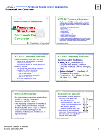
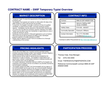
TEMPORARY OVERVOLTAGE ISSUES IN DISTRIBUTION-CONNECTED PHOTOVOLTAICSYSTEMS AND MITIGATION STRATEGIESM.E. Ropp, PhD, PEDustin Schutz, EITSteve Cozine, EITNorthern Plains Power Technologies910 4th St Suite CBrookings, SD 57006-2170Telephone: (605) 692-8687Email address: oltaic (PV) systems continue to be deployed on U.S. utility systems at a brisk pace. Asthe industry matures, it is having to contend with issues that are well-known to other types ofdistributed generator (DG) manufacturers, such as temporary overvoltage (TOV) phenomena.There are TOV concerns with PV, just as there are with other types of DG, but traditionalthinking regarding TOV prevention is largely based on experience with rotating machines,which does not necessarily directly apply to inverter-based DG like PV. One particular aspect inwhich this is true is in the requirement that PV systems present a well-grounded source to thesystem, with “effectively grounded” being defined in IEEE 142. This paper discusses therationale behind requiring the PV to be well-grounded, but also presents an argumentsuggesting that this requirement does not solve the problem, with support from a simulationstudy.IntroductionIt has long been known that distributed generators (DGs) connected to distribution feedershave the potential to cause temporary overvoltage (TOV) events, particularly during single lineto ground (SLG) faults. Photovoltaic (PV) systems are no exception, and in fact may raiseconcerns more often than other types because they tend to be installed on the lowest-voltageparts of the system, and potentially at any point on a feeder. There are five key physicalmechanisms through which DGs can drive a TOV event.TOV mechanism #1: Ground potential riseGround potential rise (GPR) is caused by the finite (actually rather low) conductivity of earth,and occurs when large currents flow into grounding conductors. This current flows through theimpedance between the grounding conductor and “remote earth” (usually assumed to be thezero-potential reference), causing a voltage to appear between the grounded conductor andthat zero reference. GPR is a somewhat complicated phenomenon, because it depends on thegeometry of the grounding conductor, soil types, soil moisture content, and other factors, andvaries strongly as a function of season [1]. GPR is discussed in IEEE standard 142-2007,“Grounding of Industrial and Commercial Power Systems” (the Green Book) [2].TOV mechanism #2: Neutral point shifting, or derived neutral shiftNeutral point shifting occurs in three-wire (delta) systems during an SLG fault, because onecorner of the delta becomes ground-referenced by the fault. Figure 1 demonstrates this1
phenomenon using vector diagrams. Assuming that the phase voltages were initially balanced,in the pre-fault condition the center of the delta is at the origin, so the “neutral point” of thedelta is at zero. When the SLG fault strikes (applied to phase b in this case), the faulted phase isnow ground-referenced. The system maintains the line-to-line voltage relationships, sovoltages Vab and Vbc remain the same post-fault, but because the delta is now referenced tophase b, Van Vab and Vcn Vbc. The problem with this is that any single-phase load connectedbetween one of the non-faulted phases and the neutral (assumed to be multigrounded) willnow see the line-line voltage, instead of the line-neutral voltage it is supposed to see. Thisovervoltage will be 1.73 p.u. if feeder impedances are neglected, which will fall outside of theCBEMA curve if it persists for more than approximately 2 msec. Damage to those single-phaseloads then becomes highly likely. This situation can occur if a PV system is connected to adistribution feeder through a delta-Yg transformer, with the delta on the HV side and the LV Yside grounded. The substation transformer usually has a grounded-Y on the feeder side, but ifthe SLG fault causes the substation breaker to open, then the feeder is being fed only by thedelta-connected PV which no longer has a ground reference on the feeder side.Figure 1. Explanation of TOV mechanism #2, neutral point shifting.TOV mechanism #3: Inductive coupling between fault currents and non-faulted phasesUnder normal operation, each phase induces a small voltage drop in neighboring phases and inthe neutral conductor because of inductive coupling of the phase current to the other phases.The mutual inductance between phases is relatively small, particularly for overhead lines, sowhen carrying load currents these induced voltages usually have only a minor effect. However,fault currents can be more than an order of magnitude larger than load currents, which causes asimilar increase in the inductively induced voltage in the unfaulted phases and in the neutral.2
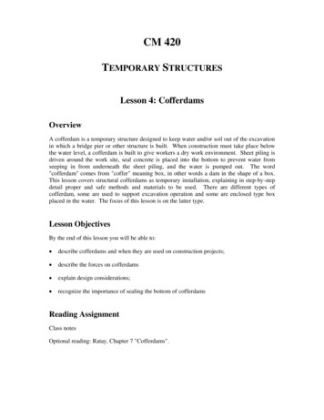
Inductive coupling is the dominant TOV-producing mechanism while the substation breaker isstill connected [3], but if the distributed generation is PV, the importance of inductive couplingusually diminishes after the breaker opens because the PV system does not supply significantlevels of fault current.TOV mechanism #4: Interruption of significant power exportThis condition occurs when a switch opens while the PV is exporting significant power back tothe system, which of course requires that the aggregate PV penetration level on the feeder besufficiently high that the PV is larger than the load during some daylight hours. This situation isdepicted in Figure 2. During export, the PV system output current iPV is larger than thatrequired by the local load, iload, and thus the current back to the grid igrid is positive. If the switchat the right opens while igrid is particularly large, then iPV iload, meaning that iload becomes muchlarger than before the switch opened. By Ohm’s law, the load voltage Vload will rise inproportion to the level of increase in iload.Figure 2. Explanation of TOV mechanism #4, interruption of significant power export.TOV mechanism #5: Interruption of inductive currentsThis problem is well known to (and hated by) power electronics engineers and designers oflarge AC interrupters. If one attempts to open a switch that is in series with an inductance whilethat inductance is carrying a current, the inductor’s magnetic field collapses and produces avoltage spike that induces an arc. This phenomenon is one key reason for the existence ofsnubbers on such switches. Any loads connected between the switch and the inductance willalso see this voltage spike.Relative importance of the five mechanismsAlthough any of the five mechanisms can be important in different circumstances, only two,mechanisms #2 (derived neutral shift) and #4 (interruption of large export current), are ofprimary importance for PV. Mechanism #1, GPR, is less important for PV than for some othertypes of DG because of PV’s limited ground current contribution, and is also more of an issueconcerning the grounding system than the specific type of DG. As noted earlier, mechanism#3, inductive coupling to fault current, is very important while the grid is connected and in3
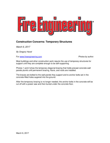
rotating-machine cases because of the large fault currents, but because PV contributions tofault current are relatively small, mechanism #3 is not dominant for PV. Similarly, mechanism#5, interruption of inductive currents, has more to do with the switches involved and the natureof system impedances than with PV in particular.Problem statementBecause of its increasing frequency of appearance as a utility concern, the focus of this paper ison mechanism #2, the derived neutral shift. As noted above, mechanism #2 occurs when a PVsystem is tied to a distribution feeder through a delta-Yg transformer and an SLG fault occurs.The utility usually presents a grounded source to the feeder via a delta-Yg substationtransformer with the Yg on the feeder side. When the substation breaker opens, the onlyremaining source (for a very brief time) is the PV, which has a delta on the feeder side. Thus,one apparent mitigating strategy would be to require the PV to connect to the feeder via a YgYg distribution transformer. However, one additional requirement is usually imposed: that thePV plant present a well-grounded source to the utility, with well-grounded defined as in IEEE142 [4]. The reason for this requirement can be understood more easily by considering the YgYg transformer schematic in Figure 3. Assume for the moment that the SLG fault is applied tophase c. The voltage VCH will then collapse to near zero, and that low voltage is transformedacross to VCX on the LV side. This means that phase c is effectively ground-referenced on theLV side of the transformer as well. If a generator is now connected to the X terminals of thetransformer, that generator’s c phase is ground referenced, and if the generator maintains thephase-phase voltage relationship (i.e., the generator fixes Vbc and Vca), then the generator’sneutral point can shift, that shifted neutral point is transformed across the Yg-Yg transformer,and the Yg-Yg transformer has not solved the problem.VAHVAXVBHVBXVCHVCXFigure 3. Schematic of a Yg-Yg transformer.4
In this case, the solution seems clear: the neutral point of the generator must be effectivelygrounded, and this is where the IEEE 142 definition comes into play. The IEEE 142 definition of“effectively grounded” requires both of the following two conditions to be met:0 0 𝑋0 3𝑋1𝑅0 1𝑋1where X0 and X1 are the generator’s zero- and positive-sequence reactances, respectively, andR0 is the generator’s zero-sequence resistance.For synchronous generators, this makes sense, and it should be noted that IEEE 142 is relativelyclear that its writers had synchronous generators in mind when the requirements weredeveloped [5]. However, for PV plants, it is very difficult to comply with the IEEE 142 definitionof effectively grounded. Because most PV inverters have relatively low positive sequencereactance (the main contributor being the isolation transformer, along with AC filterinductances), the definition of effectively grounded usually cannot be met by an impedanceground, and instead requires solid grounding [6]. Solidly grounding the PV plant in this wayleads to significant problems with neutral current flows and harmonics, along with othercontrols and reliability issues, and is thus generally undesirable. Thus, if such a costlyrequirement is to be imposed on PV systems, it is imperative to ensure that it actually doessolve the problem.Results and discussionTheoryThere is a fundamental difference between PV and a synchronous generator in that the PVappears to the grid as a controlled current source. It is key to note that the PV does not act as avoltage-behind-impedance source, as a synchronous generator does, and neither does it act asa power-controlled source. The PV inverter controls its AC output current in such a way as totry to maximize the power being extracted from the PV array at any given time. Thus, in thesmall space of time between the opening of the substation breaker and the shutdown of the PVsystem, the islanded section of the feeder can be represented as shown in Figure 4 below.This representation of the PV plant is valid as long as the inverter’s terminal voltage does notrise too high. If the voltage does rise too high, the inverter’s controls will saturate, and theinverter will enter a square-wave mode of operation, also known as six-step mode [7] in whichthe PV plant does appear as a voltage-behind-impedance source. However, this condition iseasily detectable, and most inverters incorporate self-protection means that shut the inverterdown anyway if the AC terminal voltage gets that high. Thus, it is reasonable to represent thePV as shown in Figure 4.Assume for a moment that the feeder neutral is well-grounded, and that the delta-connectedloads are either negligible, or very well balanced so that they can be lumped in with the5
grounded Y-connected load without much loss in accuracy. Consider the voltage VPV,c in Figure4. When the island forms, VPV,c becomes equal to the product of iPV,c and the equivalent phaseto-neutral impedance, by Ohm’s Law. Note that VPV,c is ground-referenced because the load isground-referenced, and VPV,c does not depend on whether the inverter is grounded. In otherwords, this argument suggests that requiring the PV plant to be an effectively-grounded sourceaccording to IEEE 142 is unnecessary, because such grounding will not affect the level of TOVproduced by a PV inverter, and thus would add cost without solving the problem.Feeder seriesimpedancePV plantiPV,c VPV,ciPV,a-iPV,bDelta-connected Y-connectedloadloadFigure 4. Highly simplified schematic of a grid-tied PV system feeding an islanded load, after opening of thesubstation breaker.Simulation study to test theoryTo investigate this phenomenon more fully, a lengthy computer simulation study wasconducted using the MATLAB-Simulink environment. First, the generic feeder modelpresented in [3] was built as shown in Figure 5. This model was selected because it isspecifically designed for TOV studies, and [3] contains all of the required feeder segmentparameters as well as model validation data. Then, a well-verified PV plant model was added.A detailed switching model was used, because it was found early in this work that a switchaveraged model, which uses a current-source representation of the power electronics,significantly overpredicted the levels of TOV seen on the feeder. (This is a subject of interest initself, but is beyond the present scope.) The inverter’s voltage measurements for control andtripping purposes are made from phase to ground. The inverters include all of the IEEE 1547trips, plus an extra high-voltage fast-trip setting that is included by most manufacturers for selfprotection purposes. The PV plant was added at a point near the substation, as shown in Figure5, because earlier work suggested that the worst case mechanism #2 TOV was produced whenthe fault was as far downstream from the PV plant as possible. Also, adding the PV plant nearthe substation provided the most flexibility in locating the fault. Consequently, the fault usedfor this work is the one labeled “Fault5” on the right side of Figure 5.6
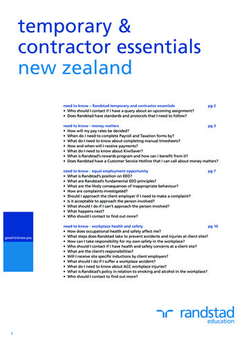
Figure 5. MATLAB/Simulink model of the feeder presented in [3].Once this was completed, the following matrix of conditions was simulated:PV to load ratios: 2:1, 1:1, 0.67:1Distribution transformer configurations: -Yg, Yg-YgIsolation transformer configurations: Y-Y, Y-Yg, -Y, -YgEvery combination of these parameter values (total of 24) was simulated. The impact of thegrounding of the 480-V side of the inverter internal isolation transformer on TOV, as seen onthe 25 kV distribution feeder, was recorded. One terminological convention that has beenadopted here should be explained: this paper refers to a “first TOV” and a “second TOV”. Thefirst TOV is the TOV that occurs after the fault occurs, but before the substation breaker opens.This TOV is caused primarily by TOV mechanisms 1 and 3, and is generally fairly small. Thesecond TOV then occurs after the substation breaker opens. If the PV to load ratio is in therange of approximately 1 to 1.5, the second TOV is caused primarily by TOV mechanism #2,derived neutral shift; for PV to load ratios larger than 1.5, the TOV becomes dominated by TOVmechanism #4, interruption of heavy export. The second TOV is the primary concern in thiswork.The results of the simulations are shown in Figures 6 and 7. Figure 6 collects the results of allsimulations in which the inverter’s isolation transformer was a Y-Y or Y-Yg (i.e., the PV systempresents an ungrounded Y to the feeder, or a grounded Y, respectively). The figure is read asfollows. There are four groups of columns in the figure. The first (leftmost) group of columnsshows voltages during the “first TOV” period if the distribution transformer is Yg-Yg, and thesecond group of columns shows the “second TOV” period for the Yg-Yg distributiontransformer. In these two groups of columns, each colored column corresponds to a specificisolation transformer configuration and generation:load ratio. The isolation transformerconfiguration (either Y-Y or Y-Yg) and generation:load ratio (2:1, 1:1, or 0.67:1) correspondingto each color of column are given in the legend at the right of the figure.The third and fourth groups of columns in Figure 6 (the rightmost two) are the same as theleftmost two just described, except that the distribution transformer is now delta-Yg (labeled7
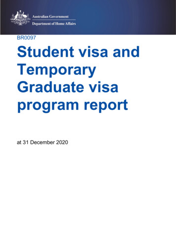
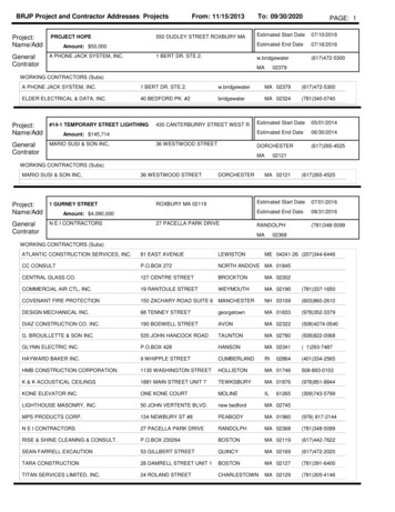
Figure 6. Peak (not RMS) line-to-ground voltages measured on the HV side of the PV distribution transformerduring the SLG fault event. Values are shown for the first TOV period (substation breaker closed) and secondTOV period (substation breaker open), for two distribution transformer configurations, Yg-Yg and delta-Yg.Colored columns correspond to specific PV inverter isolation transformer configurations and generation:loadratios, as described in the legend at the right.Figure 7. Peak (not RMS) line-to-ground voltages measured on the HV side of the PV distribution transformerduring the SLG fault event. Values are shown for the first TOV period (TOV mechanism #3 is dominant) andsecond TOV period (TOV mechanism #2 is dominant), for two distribution transformer configurations, Yg-Ygand delta-Yg. Colored columns correspond to specific PV inverter isolation transformer configurations andgeneration:load ratios, as described in the legend at the right.8
“DY” and “DYg” in the figure). Figure 7 is similar to Figure 6; the only difference is the isolationtransformer configurations, which are delta-Y and delta-Yg (compare the two right-side figurelegends). The voltages shown in Figures 6 and 7 are peak (not RMS) voltages, and are thehighest voltage recorded during the respective TOV period (first or second), on any phase.As expected, Figures 6 and 7 show that the distribution transformer makes a considerabledifference in the level of TOV seen, with much higher levels of TOV occurring for the delta-Ygtransformer because of TOV mechanism #2. It is also clear that the generation:load ratiomakes a considerable difference. A full discussion of this issue is outside the present scope, butit should be noted that when the generation:load ratio is less than unity, there really is nosecond TOV, even with a delta-Yg distribution transformer, because the power-limited PVsource has insufficient power available to drive the low-impedance load to high voltage. Whenthe generation:load ratio is greater than unity, TOV mechanism #4 comes into play, and TOVlevels rise.However, the main result for the present discussion is seen by comparing the second TOV levelswith grounded and ungrounded inverter isolation transformers. For example, consider Figure6, and focus on the rightmost group of columns, which give the second TOV for a delta-Ygdistribution transformer. Consider the case of a generation:load ratio of 1:1, which is thereddish-colored and the light blue columns (the second and fifth columns of that group). Thenumerical value of second TOV is given above each column, and they are equal at 25660 V, orabout 126% of nominal. The fact that they are equal is the important point: the grounding ofthe inverter isolation transformer made no difference. This conclusion holds for all of thesecond TOV cases with either delta-Y or Y-Y isolation transformers.ConclusionsBoth theory and simulation results support the conclusion that requiring PV inverters to beeffectively grounded according to the IEEE 142 definition is not justified by concerns arisingfrom asymmetrical fault situations and temporary overvoltage. This does NOT mean that PVsystems do not cause TOV, but it does suggest that requiring PV inverter isolation transformersto be grounded does not effectively mitigate TOV.AcknowledgmentsThe author is grateful to the following for helpful discussions in developing the conceptspresented in this paper: Marc Johnson, Advanced Energy; Tucker Ruberti, Advanced Energy;Eric Seymour, Advanced Energy; Russ Neithammer, Ballinger; Michael Behnke, BEWEngineering; and Barry Hornberger, PECO. This work was financially supported by AdvancedEnergy, and NPPT gratefully acknowledges that support.References[1][2]R. J. Heppe, “Step Potentials and Body Currents Near Grounds in Two-Layer Earth”, IEEETransactions on Power Apparatus and Systems, PAS-98 (1), Jan/Feb 1979, p. 45-59.IEEE standard 142-2007, “IEEE Recommended Practice for Grounding of Industrial andCommercial Power Systems”. The GPR discussion is in Sections 1.13, page 63, and in Subsection2.2.3, page 93.9
[3][4][5][6][7]J. Acharya, Y. Wang, W. Xu, “Temporary Overvoltage and GPR Characteristics of DistributionFeeders with Multigrounded Neutral”, IEEE Transactions on Power Delivery 25(2), April 2010, p.1036-1044.IEEE standard 142-2007, “IEEE Recommended Practice for Grounding of Industrial andCommercial Power Systems”. The definition of “effectively grounded” is on page 2, definition1.2.1.IEEE standard 142-2007, “IEEE Recommended Practice for Grounding of Industrial andCommercial Power Systems”. The discussion in Section 1.7 makes it clear that the authorsmeant “rotating generator” when they said “generator”. PV does receive a brief mention inSection 1.15.7, but that section is discussing DC-side grounding only.IEEE standard 142-2007, “IEEE Recommended Practice for Grounding of Industrial andCommercial Power Systems”. Solid grounding is defined and discussed in Section 1.4.6, page17.N. Mohan, T. Undeland, W. Robbins, Power Electronics: Converters, Applications, and Design,rd3 ed., pub. John Wiley and Sons 2003, ISBN 0471226939. Square-wave inverter operation isdescribed in Section 8-4-2, page 229, and the term “six-step mode” is defined on page 418.10
varies strongly as a function of season ]. GPR is discussed in IEEE standard 142[1 -2007, “Grounding of Industrial and Commercial Po wer Systems” (the Green Book) [2 ]. TOV mechanism #2: Neutral point shifting, or derived neutral shift Neutral point shifting occurs in th