Transcription
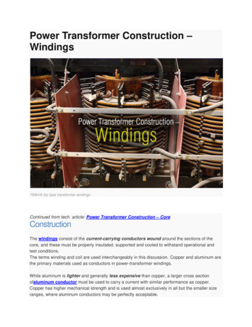
Power Transformer Construction –Windings750kVA dry type transformer windingsContinued from tech. article: Power Transformer Construction – CoreConstructionThe windings consist of the current-carrying conductors wound around the sections of thecore, and these must be properly insulated, supported and cooled to withstand operational andtest conditions.The terms winding and coil are used interchangeably in this discussion. Copper and aluminum arethe primary materials used as conductors in power-transformer windings.While aluminum is lighter and generally less expensive than copper, a larger cross sectionofaluminum conductor must be used to carry a current with similar performance as copper.Copper has higher mechanical strength and is used almost exclusively in all but the smaller sizeranges, where aluminum conductors may be perfectly acceptable.
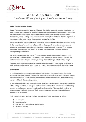
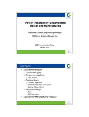
In cases where extreme forces are encountered, materials such as silver-bearing copper can beused for even greater strength.The conductors used in power transformers are typically stranded with a rectangular cross section,although some transformers at the lowest ratings may use sheet or foil conductors. Multiplestrands can be wound in parallel and joined together at the ends ofthe winding, in which case it isnecessary to transpose the strands at various points throughout the winding to prevent circulatingcurrents around the loop(s) created by joining the strands at the ends.Individual strands may be subjected to differences in the flux field due to their respective positionswithin the winding, which create differences in voltages between the strands and drive circulatingcurrents through the conductor loops.Figure 1 - Continuously transposed cable (CTC)Proper transposition ofthe strands cancels out these voltage differences and eliminates or greatlyreduces the circulating currents. A variation ofthis technique,involving many rectangular conductorstrands combined into a cable, is called continuously transposed cable (CTC), as shownin Figure 1.In core-form transformers,the windings are usually arranged concentrically around the core leg,as illustrated in Figure 2, which shows a winding being lowered over another winding already onthe core leg of a three-phase transformer.A schematic of coils arranged in this three-phase application was also shown in Figure 1(article‘Power Transformer Construction – Core’).Shell-form transformers use a similar concentric arrangement or an inter-leaved arrangement, asillustrated in the schematic Figure 3 and the photograph in Figure 7.
Figure 2 - Concentric arrangement, outer coil being lowered onto core leg over top of inner coilFigure 3 - Example of stacking (interleaved) arrangement of windings in shell-form constructionWith an interleaved arrangement, individual coils are stacked, separated by insulating barriers andcooling ducts. The coils are typically connected with the inside of one coil connected to the insideof an adjacent coil and, similarly, the outside of one coil connected to the outside of an adjacentcoil. Sets of coils are assembled into groups, which then form the primary or secondary winding.
When considering concentric windings, it is generally understood that circular windings haveinherently higher mechanical strength than rectangular windings, whereas rectangular coils canhave lower associated material and labor costs.Rectangular windings permit a more efficient use of space, but their use is limited to smallpowertransformers and the lower range of medium-power transformers, where the internal forces arenot extremely high. As the rating increases, the forces significantly increase, and there is need foradded strength in the windings, so circular coils, or shell-form construction are used.In some special cases, elliptically shaped windings are used.Concentric coils are typically wound over cylinders with spacers attached so as to form a ductbetween the conductors and the cylinder. The flow of liquid through the windings can be basedsolely on natural convection, or the flow can be somewhat controlled through the useof strategically placed barriers within the winding.Figures 4 and 5 show winding arrangements comparing nondirected and directed flow. Thisconcept is sometimes referred to as guided liquid flow.Figure 4 - Nondirected flow
A variety of different types of windings have been used in power transformers through the years.Coils can be wound in an upright, vertical orientation, as is necessary with larger, heavier coils;or they can be wound horizontally and placed upright upon completion.As mentioned previously, the type of winding depends on the transformer rating as well as thecore construction. Several of the more common winding types are discussed below.Figure 5 - Directed flowPancake WindingsSeveral types of windings are commonly referred to as “pancake” windings due to thearrangement of conductors into discs. However, the term most often refers to a coil type that isused almost exclusively in shell-form transformers.The conductors are wound around a rectangular form, with the widest face of the conductororiented either horizontally or vertically. Figure 6 illustrates how these coils are typically wound.This type of winding lends itself to the interleaved arrangement previously discussed (Figure 7).
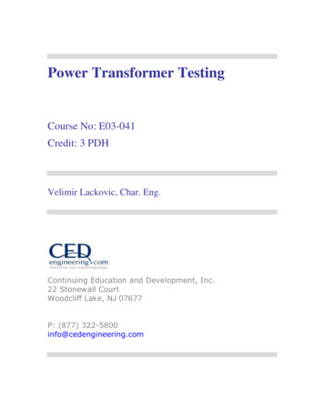
Figure 6 - Pancake winding during winding processFigure 7 - Stacked pancake windingsLayer (Barrel) WindingsLayer (barrel) windings are among the simplest of windings in that the insulated conductors arewound directly next to each other around the cylinder and spacers.Several layers can be wound on top of one another, with the layers separated by solidinsulation,ducts,or a combination. Several strands can be wound in parallel ifthe currentmagnitude so dictates.
Variations of this winding are often used for applications such as tap windings used in load-tapchanging (LTC) transformers and for tertiary windings used for,among other things,thirdharmonic suppression.Figure 8 shows a layer winding during assembly that will be used as a regulating winding in anLTC transformer.Figure 8 - Layer windings (single layer with two strands wound in parallel)Helical WindingsHelical windings are also referred to as screw or spiral windings, with each term accuratelycharacterizing the coil’s construction.A helical winding consists of a few to more than 100 insulated strands wound in parallelcontinuously along the length of the cylinder, with spacers inserted between adjacent turnsor discs and suitable transpositions included to minimize circulating currents between parallelstrands.
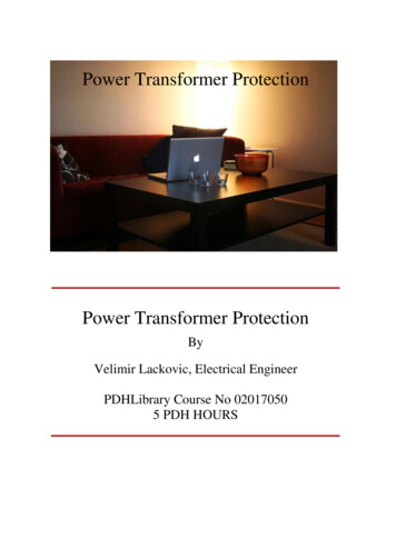
Figure 9 - Helical winding during assemblyThe manner of construction is such that the coil resembles a corkscrew. Figure 9 shows a helicalwinding during the winding process. Helical windings are used for the higher-current applicationsfrequently encountered in the lower-voltage classes.Disc WindingsA disc winding can involve a single strand or several strands of insulated conductors wound in aseries of parallel discs of horizontal orientation, with the discs connected at either the inside oroutside as a crossover point. Each disc comprises multiple turns wound over other turns, with thecrossovers alternating between inside and outside.
Figure 10 - Basic disc winding layoutFigure 11 - Disc winding inner and outer crossoversFigure 10 outlines the basic concept, and Figure 11 shows typical crossovers during the windingprocess.
Most windings of 25-kV class and above used in core-form transformers are disc type. Given thehigh voltages involved in test and operation, particular attention is required to avoid high stressesbetween discs and turns near the end of the winding when subjected to transient voltage surges.Numerous techniques have been developed to ensure an acceptable voltage distribution along thewinding under these conditions.Reference: Electric Power Transformer Engineering, published May 16, 2012 by CRC Press// chapter Power Transformers authored by H.J. Sim and S.H. Digby (Get this ebook from al.com/power-transformer-construction-windings
May 16, 2012 · Power Transformer Construction – Windings 750kVA dry type transformer windings Continued from tech. article: Power Transformer Construction – Core Construction The windings consist of the current-carrying conductors wound around the sections of the core, and these must be properly ins