Transcription
9/24/2013Power Transformer Factory Testusing IEEE StandardsWaldemar ZiomekCG Power Systems CanadaIEEE Training, Houston, Texas, Oct.8-9, 2014Power transformer testingPower Transformer Factory testTopics covered Objective of tests Classification of tests List of tests Connections for test Details of Tests Sequence of tests Future trendsTests for special transformers, such as HVDC converteror Phase shifting transformers are not coveredPower transformer testing21
9/24/2013Objective of testing Compliance to applicable standards Compliance to customer specification Verify guaranteed parameters Assess quality and reliability Verify design Obtain additional performance andreference dataPower transformer testing3Classification of testsAs per IEEE standards Routine test Design test Other testsAs per characteristic of test Quality verification tests Performance tests Thermal tests Dielectric tests Mechanical tests Test data for future reference OthersPower transformer testing42
9/24/2013IEEE standards IEEE standard C57.12.00IEEE Standard General Requirements for Liquid-Immersed,Distribution, Power and Regulating TransformersIEEE standard C57.12.90IEEE Standard Test Code for Liquid -Immersed, Distribution,Power and Regulating TransformersandIEEE Guide for Short-Circuit Testing of Distribution andPower Transformers CSA standard CAN/CSA-C88-M90CSA standard for Power transformers and reactors5Power transformer testingList of testsRoutine Design OtherRemarkOil quality testsXQualityResistance measurementXQualityWinding Insulation resistanceXQualityCore/clamp insulation resistance XQualityRatio testXPolarity and phase relationshipXQuality andperformanceInsulation power factor andcapacitanceXQuality andFuture ref.Control (auxiliary) lossesXOthersSingle phase excitation testXFuturereference63
9/24/2013List of testsRoutineDesign Others RemarkNo load loss and excitationcurrentXXPerformancetestLTC operation with no loadvoltage (cycle recording)XQualityverificationImpedance voltage and loadlossXPerformancetestLTC operation at load current X(cycle recording)QualityverificationZero phase sequence voltageTemperature riseXXFuture/SystemreferenceXThermal andperformance7List of testsDielectric testsRoutineLightning impulseDesign Others RemarkXSwitching impulseXDielectrictestXDielectrictestApplied voltage testXDielectrictestInduced voltage with or withoutpartial discharge measurementXDielectrictestNo load loss after dielectricsXCSALow or Power frequency test onauxiliary / control devices andcurrent transformersXDielectrictest84
9/24/2013List of testsRoutine Design Others RemarkAudible sound levelXPerformanceShort circuit capabilityXPerformanceand quality testOperation tests of all devices XQualityverificationDissolved gas in oil analysisQuality,Thermal, FuturereferenceXLifting and moving devicesXMechanical testPressureXMechanical testLeakXQualityverification9Test system accuracy requirementQuality measuredAccuracyLosses /-3%Voltage /-0.5%Current /-0.5%Resistance /-0.5%Temperature /-1.0degCFrequency of test source to be within /-0.5%of rated frequency105
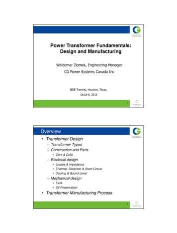
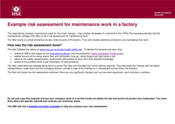
9/24/2013Open circuit connectionRatio testNo load loss and current testSound level testInduced voltage test11Measurement of no load loss and current126
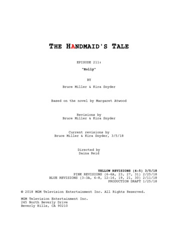
9/24/2013Equivalent circuit on open circuit connection13Short circuit connection Impedance and load loss Temperature rise147
9/24/2013Measurement of impedance and load loss15Equivalent circuit on short circuit connection168
9/24/2013Special connection Zero phase sequence voltage17Dielectric testsWithstand voltageBILSILInduced voltageApplied voltageImpact on designBushings, lead clearances, windinginternal insulation, winding clearances,stresses to ground, neutral pointinsulationExternal clearances, Bushings, leadclearances, phase-to-phase stressesInternal winding stresses (V/T), stressesto ground, grounding, electrodeconfigurationsStresses to ground (windings, leads).Critical for fully insulated windings189
9/24/2013Insulation types19Insulation stressed by different tests2010
9/24/2013Impulse wave shapesp.u.V1.3 (FoW)1.1 (CW)1.0 BILBILFWCW0.83 SILSIL0.5 1.2µs 1.2µs3-5µs50µsTime21Lightning impulse Full wave2211
9/24/2013LI chop wave shape23LI test connections2412
9/24/2013LI test connections25LI test connections2613
9/24/2013Lightning impulse test sequenceWithout non linear resistors in the unit Reduced (50%) full wave 100% Chopped wave 100% Chopped wave 100% Full wave27Lightning impulse test sequenceWith non linear resistors in the unit 50% Full wave 80% Full wave 100% Full wave 100% Chopped wave 100% Chopped wave 100% Full wave 80% Full wave 50% Full wave2814
9/24/2013Lightning impulse failure detectionFailure detection is by comparison of voltage and currentwave shapes at reduced level and full level or between 2wave shapes at the same level in case of non-linear resistors29Lightning impulse test on neutralWave shape:Front time 10 micro secTail time 50 micro secTest sequence: Reduced full wave 2x100% full wave3015
9/24/2013Dielectric tests-Switching impulse SequenceReduced Full wave followed by 2 Full waves (opposite polarityapplication required to demagnetize core)31Switching impulse waveshape3216
9/24/2013Switching impulse connection1.5PU Ph-PhReduced FW and FW voltage wave shapes arecompared for pass criteria33Dielectric tests-Applied voltage3417
9/24/2013Applied voltage test35Applied voltage test connection3618
9/24/2013Dielectric tests-Induced voltage37Induced voltage test3819
9/24/2013Induced voltage testTest voltage and duration For class II transformers ( 69kV Class) Test voltage is raised slowly to 150% and held for few minutes andis raised to Enhancement level of approximately 173% for 7200cycles and then reduced to 150% and maintained for 1 hour During this test partial discharge (apparent charge) in picocoulombs is recorded every 5 minutes As per ANSI-IEEE standards the limit for PD level is 500pC(Alternate measurement can be RIV in micro-volts in which case thelimit is 100micro-volts. But this is not a preferred method, wasmoved to annex in the IEEE standard)39Measurement of partial discharge4020
9/24/2013Partial discharge display41Time sequence for induced test4221
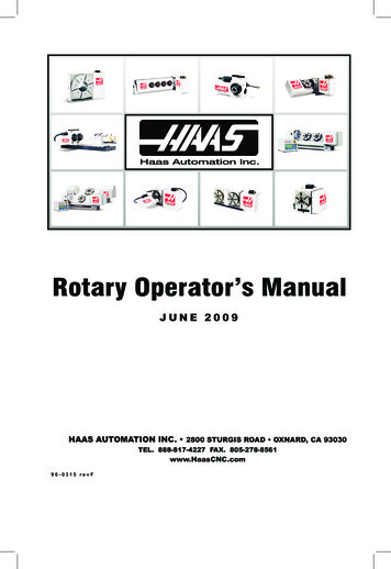
9/24/2013Examples of Common Discharge and Interference PatternsEncountered During Partial Discharge Tests on Power Transformersa) Corona discharge on a highvoltage electrodeb) Corona discharge on a groundedpointc) Unearthed conductive object nearor inside the test objectd) Noise due to a bad contact (thispattern may also occur in sometype of internal discharges)e) PD in oil-paper insulation or gasbubblesf) Surface (creeping) discharge in oilg) Interference due to thyristorpulsesh) Interference due to a modulatedperiodic signal4343Phase-resolved PD patternsa)b)Discharges in solid insulationwith cavitiesBubbles in oil; the pattern isappearing and disappearingc)Floating potentiald)RIP bushing problem444422
9/24/2013Temperature rise test45Temperature rise testCorrection required for sites at altitudes 3300ft4623
9/24/2013Dissolved gas analysis47Sound level test Connection same as for no load test Sound pressure level measured at 0.3m(1foot)distance from sound producing surface (tank) Sound pressure level measured at 2 m (6feet)distance from fans when forced cooling inoperation. Measurement done at 1/3 and 2/3 height of tank A weighted sound pressure level is computed Correction done for ambient noise4824
9/24/2013Sound level test In addition to compliance to C57.12.90, HECO alsospec IEC 60076-10. "Sound pressure and soundpower level specifications shall apply for conditionswith all ventilation fans ON, and for both no load(open secondary) and rated load operatingconditions." Sound pressure vs. sound power Sound measurement under load– Measure the winding sound during heat run– Measurements under load logarithmically added tocore noise49Test sequenceLow voltage/rated voltage tests RatioPolarityResistanceCore lossLoad lossZero sequenceTemperature rise/overload5025
9/24/2013Test sequenceDielectric tests Lightning impulseSwitching impulseApplied voltage testInduced voltage/Partial discharge testRepeat no load test when specified51Other tests and trends in test requirements Sweep Frequency Response Analysis– Total assembled condition– Shipping condition Recurrent surge generator testDirect hotspot measurement using fiber opticsInfrared scan during temperature rise testPartial discharge for 69kV class unitsSound level using intensity meter andsound level under load Tests on buried tertiary winding Acoustic detection of partial dischargeproblem5226
9/24/2013QuestionsThank you for your participation5327
IEEE standards IEEE standard C57.12.00 IEEE Standard General Requirements for Liquid-Immersed, Distribution, Power and Regulating Transformers IEEE standard C57.12.90 IEEE Standard Test Code for Liquid -Immersed, Distribution, Power and Regulating Transformers and IEEE Guide for Short-Circuit Testing of Distribution and Power Transformers CSA standard CAN/CSA-C88-M90 CSA standard for .