Transcription
https://www.halvorsen.blogArduino PWM andAnalog OutputHans-Petter Halvorsen
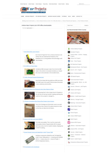
Arduino is an open-source physical computing platformdesigned to make experimenting with electronics andprogramming more fun and intuitive. Arduino has its own unique, simplified programming languageand a lots of premade examles and tutorials exists. With Arduino you can easily explore lots of small-scale sensorsand actuators like motors, temperature sensors, etc. The possibilities with Arduino are endeless.http://www.arduino.cc
ArduinoMicrocontrollerUSBArduino is an open-source electronics platform
Contents Introduction to Pulse WidthModulation (PWM) Arduino analogWrite() function Arduino UNO has no true AnalogOutputs. What can we do?
https://www.halvorsen.blogPulse WidthModulation (PWM)Hans-Petter Halvorsen
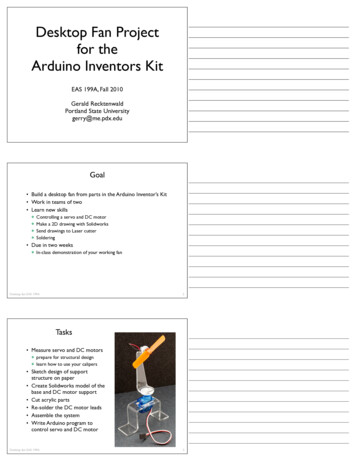
PWMPWM is a digital (i.e. square wave) signal that oscillates according to a given frequency andduty cycle.The frequency (expressed in Hz) describes how often the output pulse repeats.The period is the time each cycle takes and is the inverse of frequency.The duty cycle (expressed as a percentage) describes the width of the pulse within thatfrequency window.You can adjust the duty cycleto increase or decrease theaverage "on" time of thesignal. The following diagramshows pulse trains at 0%,25%, and 100% pwm.html
Pulse-Width Modulation (PWM)
Pulse-Width Modulation (PWM)The “shocking truth” behind analogWrite(): We know that the Arduino can read analog voltages (voltages between 0 and 5 volts)using the analogRead() function. Is there a way for the Arduino to output analog voltages as well? The answer is no. andyes. Arduino does not have a true analog voltage output. But, because Arduino is sofast, it can fake it using something called PWM ("Pulse-Width Modulation"). The pins onthe Arduino with “ ” next to them are PWM/Analog out compatible. The Arduino is so fast that it can blink a pin on and of almost 1000 times per second.PWM goes one step further by varying the amount of time that the blinking pin spendsHIGH vs. the time it spends LOW. If it spends most of its time HIGH, a LED connected tothat pin will appear bright. If it spends most of its time LOW, the LED will look dim.Because the pin is blinking much faster than your eye can detect, the Arduino createsthe illusion of a "true" analog output. To smooth the signal even more, we will create and use a RC circuit (Lowpass Filter)
Pulse-Width Modulation (PWM) The Arduino's programming language makes PWM easy to use; simply callanalogWrite(pin, dutyCycle), where dutyCycle is a value from 0 to 255, and pin is oneof the PWM pins (3, 5, 6, 9, 10, or 11). The analogWrite function provides a simple interface to the hardware PWM, butdoesn't provide any control over frequency. (Note that despite the function name, theoutput is a digital signal, often referred to as a square wave.)0 5𝑉 0 255 𝑦 𝑥 51𝑥𝑢 0𝑉 𝑎𝑛𝑎𝑙𝑜𝑔𝑊𝑟𝑖𝑡𝑒 0𝑢 5𝑉 𝑎𝑛𝑎𝑙𝑜𝑔𝑊𝑟𝑖𝑡𝑒 255𝑢 𝑥𝑉 𝑎𝑛𝑎𝑙𝑜𝑔𝑊𝑟𝑖𝑡𝑒 51 nce/AnalogWriteSecrets of Arduino duinoPWM
https://www.halvorsen.blogUsing analogWrite()Hans-Petter Halvorsen
analogWriteint ledPin 9;int value 0;void setup(){pinMode(ledPin, OUTPUT);}This functions write an “analog value”(PWM signal) to the specified pin. Youcan e.g., use it to make a LED light withdifferent intensity.Syntax:void loop()analogWrite(pin, value){where value is a value between 0 and 255value random(256);analogWrite(ledPin, value);delay(1000);Writes an analog value (PWM wave) to a pin.}sCan be used to light a LED at varyingbrightness's or drive a motor at variousspeeds. After a call to analogWrite(), the pinwill generate a steady rectangular wave ofthe specified duty cycle until the next call toanalogWrite()Note! You need to use one of the pins marked with https://www.arduino.cc/en/Reference/AnalogWrite
analogWrite()Arduino can give a signal between 0 and 5𝑉0.5𝑉:0.5100% 10%50.5V (10% of 255) - analogWrite(pin, 25)2.52.5𝑉:100% 50%5Arduino syntax: analogWrite(pin, value)value: the duty cycle: between 0 (alwaysoff) and 255 (always on).0-5V - 0-2552.5V (50% of 255) - analogWrite(pin, 127)4.5𝑉:4.5100% 90%54.5V (90% of 255) - analogWrite(pin, 229)
https://www.halvorsen.blogTrue Analog OutHans-Petter Halvorsen
Arduino Analog Out Arduino UNO has no true built-in Analog OutputChannels (only PWM) What if we need a real Analog Out Signal (0-5V)? We will use a 2 different options:– Create a RC Lowpass Filter that converts PWM toVoltage– Use a DAC chip/IC (Digital to Analog Converter) Such a chip uses either the SPI bus or the I2C bus
https://www.halvorsen.blogLowpass Filter usingRC CircuitHans-Petter Halvorsen
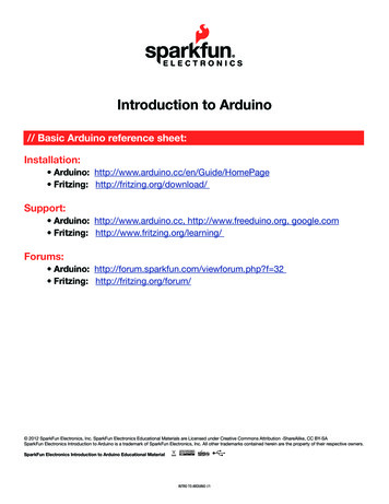
Option 1: Convert PWM to Voltagee.g., 𝑅 3.9𝑘ΩRC Lowpass Filter:e.g., 𝐶 10𝜇𝐹 rt-PWM-to-Voltage/ -pwm-to-voltage/
Electrical ComponentsCapacitore.g., 𝐶 10𝜇𝐹Resistor𝑅 3.9𝑘ΩA capacitor stores and releases electrical energy in acircuit. When the circuits voltage is higher than what isstored in the capacitor, it allows current to flow in, givingthe capacitor a charge. When the circuits voltage is lower,the stored charge is released. Often used to smoothfluctuations in voltagehttps://en.wikipedia.org/wiki/CapacitorA resistor resists the flow of electrical energy in acircuit, changing the voltage and current as a result(according to Ohms law, 𝑈 𝑅𝐼). Resistor values aremeasured in ohms (Ω). The color stripes on the sidesof the resistor indicate their values. You can also usea Multi-meter in order to find the value of a givenresistor.These electronics components are typically included in a “Starter Kit”, or they can be bought “everywhere” for a few bucks.
CapacitorThe Capacitor is typically included in the ArduinoStarter Kit (or similar Kits).If you don't have such a Kit you may buy capacitorsfrom Elfa, Kjell & Company, etc.Note! You can also easily measure the capacitance using a Multimeter. A Multi-meter that cost from 400-500 NOK has built-insupport for measuring capacitors (same for resistors andresistance).We will use the capacitor to create a RC Lowpass Filter in order tosmooth the PWM signal from the Arduino to make a “true”Analog Out Signale.g., 𝐶 10𝜇𝐹
https://www.halvorsen.blogDigital to AnalogConverters (DAC)Hans-Petter Halvorsen
Option 2Using a DAC chip DAC – Digital to Analog Converter Use, e.g., Microchip MCP4911, MCP4725 orsimilar SPI Arduino Library:https://www.arduino.cc/en/Reference/SPI MCP49XX Arduino e/master/Arduino/Libraries
DACMCP4725Arduino UNO has no Analog Output Pins, so we need aDAC such as, e.g., Microchip MCP4911, MCP4725 orsimilarMCP4911: 10-bit single DAC, SPI Interface12-bit resolutionI2C InterfaceThe MCP4725 is a little moreexpensive, but simpler to useMicrochip MCP4911 can be bought “everywhere” (10 NOK).
SPI Bus Serial Peripheral Interface (SPI) is a synchronous serial data protocol used bymicrocontrollers for communicating with one or more peripheral devices quickly overshort distances. With an SPI connection there is always one master device (usually a microcontroller)which controls the peripheral devices. SPI devices communicate in full duplex mode using a master-slave architecture with asingle master. The interface was developed by Motorola and has become a de facto standard. Typical applications include sensors, Secure Digital cards, and liquid crystal displays(LCD).SCLK : Serial Clock (output from master)MOSI : Master Output, Slave Input (output from master)MISO : Master Input, Slave Output (output from slave)SS (or SC) : Slave Select (active low, output from master)http://en.wikipedia.org/wiki/Serial Peripheral Interface ipheral-interface-spi
Arduino SPI https://www.arduino.cc/en/Reference/SPI and-the-spi-bus/ ow-do-you-use-spi-on-an-arduino ral-interface-spi
I2C Bus I²C (Inter-Integrated Circuit), is a multi-master, multi-slave,single-ended, serial computer bus It is typically used for attaching lower-speed peripheral ICs toprocessors and microcontrollers. I²C is typically spelled I2C (pronounced I-two-C) The I²C bus was developed in 1982 by Philips Semiconductor. The I²C protocol requires only 2 wires for connecting all theperipheral to a tps://learn.sparkfun.com/tutorials/i2c
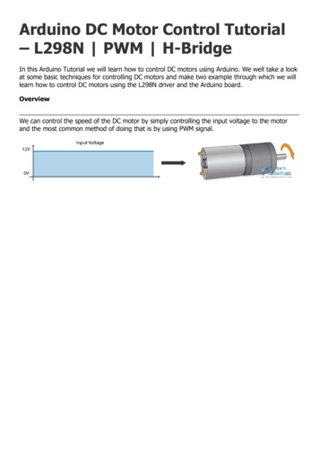
MCP4911: 10-bit single DACMCP4911ArduinoDAC𝑉HH 5𝑉𝑉OO 0𝑉The LDAC input can be used to select the device,and you could use a GPIO pin to turn the device onand off through this pin. In this example, we just tieit to ground so it is always selected and powered.Analog Out (0-5V)𝐿𝐷𝐴𝐶8 7 6 5MCP49111 2 3 4𝑆𝐷𝐼𝑆𝐶𝐾𝐶𝑆𝑉OOMISO Not Used, since we get nothing back from DAC IC𝑉EFG𝑉HH𝑉IJKSCK (13)MISO (12)MOSI (11)SS (10)
MCP49xx Arduino Library Example//Include the Arduino SPI Library//Include the MCP49xx Arduino Library// The Arduino pin used for the slave select / chip select#define SS PIN 10//Set up the DAC DAC MCP4911DAC MCP49xx dac(DAC MCP49xx::MCP4911, SS PIN);void setup(){}void loop(){double u; //Control Signal// For MCP4911, use values below (but including) 1023 (10 bit)u 255; //Simulating the Control Valuedac.output(u);delay(5000);u 512; //Simulating the Control Valuedac.output(u);delay(5000);}The control signal (u) shouldcome from the PI/PIDcontroller function.It need to be converted from 05V (or 0-100%) - 0-1023before we send it to the DACConnect the circuit (Arduino MCP4911) on abreadboard. Use a multi-meter so see if you getthe correct output master/Arduino/Libraries#include SPI.h #include DAC MCP49xx.h Example
MCP49xx Arduino Library Example#include SPI.h #include DAC MCP49xx.h Example//Include the Arduino SPI Library//Include the MCP49xx Arduino Library// The Arduino pin used for the slave select / chip select#define SS PIN 10DAC MCP49xx dac(DAC MCP49xx::MCP4911, SS PIN);void setup(){Serial.begin(9600);}void loop(){double u; //Control Signalint aiPin 0;int aiValue;for (int i 0; i 1023; i ){u i;dac.output(u);aiValue analogRead(aiPin);Serial.print("AIValue ");Serial.println(aiValue);delay(1000);}}Connect the circuit (Arduino MCP4911) on abreadboard. Use a multi-meter so see if you get thecorrect output signal.On the Multimeter you should see the output slowlyincreasing from 0V to 5V with intervals of 1000ms.You can also connect the output from the DAC to anAnalog Input Pin on the Arduino. Write the value tothe Serial Monitor.
Alternative SolutionMCP472512-bit resolutionI2C InterfaceThe MCP4725 is a little more expensive(than MCP49xx), but simpler to nalogconverter-tutorial/
Hans-Petter HalvorsenUniversity of South-Eastern Norwaywww.usn.noE-mail: hans.p.halvorsen@usn.noWeb: https://www.halvorsen.blog
yes. Arduino does not have a true analog voltage output. But, because Arduino is so fast, it can fake it using something called PWM ("Pulse-Width Modulation"). The pins on the Arduino with “ ” next to them are PWM/Analog out compatible. The Arduino is so fast that i