Transcription
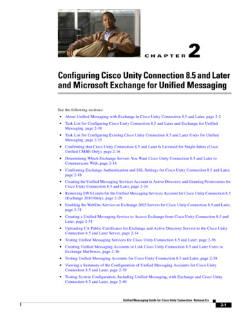
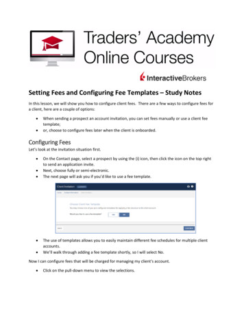
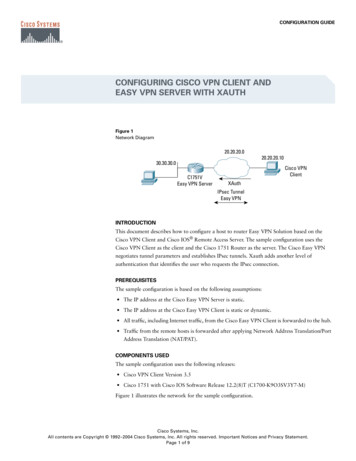
C H A P T E R10Understanding and Configuring VLANsThis chapter describes VLANs on Catalyst 4500 series switches. It also provides guidelines, procedures,and configuration examples.This chapter includes the following major sections:Note Overview of VLANs, page 10-1 VLAN Configuration Guidelines and Restrictions, page 10-3 VLAN Default Configuration, page 10-4 Configuring VLANs, page 10-4For complete syntax and usage information for the switch commands used in this chapter, refer to theCatalyst 4500 Series Switch Cisco IOS Command Reference and related publications software/ios122/122cgcr/index.htm.Overview of VLANsA VLAN is a group of devices on one or more LANs that are configured to communicate as if they wereattached to the same wire, when in fact they are located on a number of different LAN segments. BecauseVLANs are based on logical instead of physical connections, they are extremely flexible.VLANs define broadcast domains in a Layer 2 network. A broadcast domain is the set of all devices thatwill receive broadcast frames originating from any device within the set. Broadcast domains are typicallybounded by routers because routers do not forward broadcast frames. Layer 2 switches create broadcastdomains based on the configuration of the switch. Switches are multiport bridges that allow you to createmultiple broadcast domains. Each broadcast domain is like a distinct virtual bridge within a switch.You can define one or many virtual bridges within a switch. Each virtual bridge you create in the switchdefines a new broadcast domain (VLAN). Traffic cannot pass directly to another VLAN (betweenbroadcast domains) within the switch or between two switches. To interconnect two different VLANs,you must use routers or Layer 3 switches. See the “Overview of Layer 3 Interfaces” section on page 23-1for information on inter-VLAN routing on Catalyst 4500 series switches.Figure 10-1 shows an example of three VLANs that create logically defined networks.Software Configuration Guide—Release 12.2(25)EWOL-6696-0110-1
Chapter 10Understanding and Configuring VLANsOverview of VLANsFigure 10-1 Sample co routerFloor 3FastEthernetFloor 216751Floor 1VLANs are often associated with IP subnetworks. For example, all of the end stations in a particular IPsubnet belong to the same VLAN. Traffic between VLANs must be routed. You must assign LANinterface VLAN membership on an interface-by-interface basis (this is known as interface-based orstatic VLAN membership).You can set the following parameters when you create a VLAN in the management domain:Note VLAN number VLAN name VLAN type VLAN state (active or suspended) Maximum transmission unit (MTU) for the VLAN Security Association Identifier (SAID) VLAN number to use when translating from one VLAN type to anotherWhen the software translates from one VLAN type to another, it requires a different VLAN number foreach media type.Software Configuration Guide—Release 12.2(25)EW10-2OL-6696-01
Chapter 10Understanding and Configuring VLANsVLAN Configuration Guidelines and RestrictionsVLAN Configuration Guidelines and RestrictionsFollow these guidelines and restrictions when creating and modifying VLANs in your network: Before creating a VLAN, put the Catalyst 4500 series switch in VTP server mode or VTPtransparent mode. If the Catalyst 4500 series switch is a VTP server, you must define a VTP domain.For information on configuring VTP, see Chapter 27, “Understanding and Configuring VTP.” The Cisco IOS end command is not supported in VLAN database mode. You cannot use Ctrl-Z to exit VLAN database mode.VLAN RangesNoteYou must enable the extended system ID to use 4094 VLANs. See the “Understanding the Bridge ID”section on page 14-2.With Cisco IOS Release 12.2(25)EW and later, Catalyst 4500 series switches support 4096 VLANs incompliance with the IEEE 802.1Q standard. These VLANs are organized into three ranges: reserved,normal, and extended.Some of these VLANs are propagated to other switches in the network when you use the VLANTrunking Protocol (VTP). The extended-range VLANs are not propagated, so you must configureextended-range VLANs manually on each network device.Table 10-1 describes the uses for VLAN ranges.Table 10-1 VLAN RangesVLANsRangeUsagePropagatedby VTP0, 4095ReservedFor system use only. You cannot see or use these VLANs.N/A1NormalCisco default. You can use this VLAN but you cannot delete it.Yes2–1001NormalUsed for Ethernet VLANs; you can create, use, and delete these VLANs.Yes1002–1005NormalCisco defaults for FDDI and Token Ring. You cannot delete VLANs 1002–1005.Yes1006–4094ExtendedFor Ethernet VLANs only. When configuring extended-range VLANs, note thefollowing:No Layer 3 ports and some software features require internal VLANs. InternalVLANs are allocated from 1006 and up. You cannot use a VLAN that has beenallocated for such use. To display the VLANs used internally, enter the showvlan internal usage command. Switches running Catalyst product family software do not supportconfiguration of VLANs 1006–1024. If you configure VLANs 1006–1024,ensure that the VLANs do not extend to any switches running Catalyst productfamily software. You must enable the extended system ID to use extended range VLANs. Seethe “Enabling the Extended System ID” section on page 14-8.Software Configuration Guide—Release 12.2(25)EWOL-6696-0110-3
Chapter 10Understanding and Configuring VLANsVLAN Default ConfigurationConfigurable Normal-Range VLAN ParametersNoteEthernet VLANs 1 and 1006 through 4094 use only default values.You can configure the following parameters for VLANs 2 through 1001: VLAN name VLAN type VLAN state (active or suspended) SAID STP type for VLANsVLAN Default ConfigurationTable 10-2 shows the default VLAN configuration values.Table 10-2 Ethernet VLAN Defaults and RangesNoteParameterDefaultValid ValuesVLAN ID11–4094VLAN nameVLANx, where x is a number assigned bythe software.No range802.10 SAID100,0011–4,294,967,294MTU size15001500–18,190Translational bridge 110020–1005Translational bridge 210030–1005VLAN stateactiveactive; suspend; shutdownCatalyst 4500 series switches do not support Token Ring or FDDI media. The switch does not forwardFDDI, FDDI-NET, TrCRF, or TrBRF traffic, but it does propagate the VLAN configuration via VTP. Thesoftware reserves parameters for these media types, but they are not truly supported.Configuring VLANsNoteBefore you configure VLANs, you must use VLAN Trunking Protocol (VTP) to maintain global VLANconfiguration information for your network. For complete information on VTP, see Chapter 27,“Understanding and Configuring VTP.”Software Configuration Guide—Release 12.2(25)EW10-4OL-6696-01
Chapter 10Understanding and Configuring VLANsConfiguring VLANsNoteVLANs support a number of parameters that are not discussed in detail in this section. For completeinformation, refer to the Catalyst 4500 Series Switch Cisco IOS Command Reference.NoteThe VLAN configuration is stored in the vlan.dat file, which is stored in nonvolatile memory. You cancause inconsistency in the VLAN database if you manually delete the vlan.dat file. If you want tomodify the VLAN configuration or VTP, use the commands described in the following sections and inthe Catalyst 4500 Series Switch Cisco IOS Command Reference.These sections describe how to configure VLANs: Configuring VLANs in Global Configuration Mode, page 10-5 Configuring VLANs in VLAN Database Mode, page 10-7 Assigning a Layer 2 LAN Interface to a VLAN, page 10-8Configuring VLANs in Global Configuration ModeIf the switch is in VTP server or transparent mode (see the “Configuring VTP” section on page 27-6),you can configure VLANs in global and VLAN configuration modes. When you configure VLANs inglobal and config-vlan configuration modes, the VLAN configuration is saved in the vlan.dat files, notthe running-config or startup-config files. To display the VLAN configuration, enter the show vlancommand.If the switch is in VLAN transparent mode, use the copy running-config startup-config command tosave the VLAN configuration to the startup-config file. After you save the running configuration as thestartup configuration, the show running-config and show startup-config commands display the VLANconfiguration.NoteWhen the switch boots, if the VTP domain name and VTP mode in the startup-config and vlan.dat filesdo not match, the switch uses the configuration in the vlan.dat file.You use the interface configuration command mode to define the port membership mode and add andremove ports from a VLAN. The results of these commands are written to the running-config file, andyou can display the contents of the file by entering the show running-config command.User-configured VLANs have unique IDs from 1 to 4094. To create a VLAN, enter the vlan commandwith an unused ID. To verify whether a particular ID is in use, enter the show vlan id ID command. Tomodify a VLAN, enter the vlan command for an existing VLAN.See the “VLAN Default Configuration” section on page 10-4 for the list of default parameters that areassigned when you create a VLAN. If you do not use the media keyword when specifying the VLANtype, the VLAN is an Ethernet VLAN.Software Configuration Guide—Release 12.2(25)EWOL-6696-0110-5
Chapter 10Understanding and Configuring VLANsConfiguring VLANsTo create a VLAN, perform this task:CommandPurposeStep 1Switch# configure terminalEnters global configuration mode.Step 2Switch(config)# vlan vlan IDSwitch(config-vlan)#Adds an Ethernet VLAN.NoteYou cannot delete the default VLANs for these media types:Ethernet VLAN 1 and FDDI or Token Ring VLANs 1002 to1005.When you delete a VLAN, any LAN interfaces configured asaccess ports assigned to that VLAN become inactive. Theyremain associated with the VLAN (and thus inactive) until youassign them to a new VLAN.You can use the no keyword to delete a VLAN.When the prompt reads Switch(config-vlan)#, you are invlan-configuration mode. If you wish to change any of the parametersfor the newly created VLAN, use this mode.Step 3Switch(config-vlan)# endReturns to enable mode from vlan-configuration mode.Step 4Switch# show vlan [id name] vlan nameVerifies the VLAN configuration.When you create or modify an Ethernet VLAN, note the following: Because Layer 3 ports and some software features require internal VLANs allocated from 1006 andup, configure extended-range VLANs starting with 4094 and work downward. You can configure extended-range VLANs only in global configuration mode. You cannot configureextended-range VLANs in VLAN database mode. Layer 3 ports and some software features use extended-range VLANs. If the VLAN you are tryingto create or modify is being used by a Layer 3 port or a software feature, the switch displays amessage and does not modify the VLAN configuration.This example shows how to create an Ethernet VLAN in global configuration mode and verify theconfiguration:Switch# configure terminalSwitch(config)# vlan 3Switch(config-vlan)# endSwitch# show vlan id 3VLAN NameStatusPorts---- -------------------------------- --------- ------------------------------3VLAN0003activeVLAN Type SAIDMTUParent RingNo BridgeNo Stp BrdgMode Trans1 Trans2---- ----- ---------- ----- ------ ------ -------- ---- -------- ------ -----3enet 1000031500 00Primary Secondary TypeInterfaces------- --------- ----------------- oftware Configuration Guide—Release 12.2(25)EW10-6OL-6696-01
Chapter 10Understanding and Configuring VLANsConfiguring VLANsConfiguring VLANs in VLAN Database ModeWhen the switch is in VTP server or transparent mode, you can configure VLANs in the VLAN databasemode. When you configure VLANs in VLAN database mode, the VLAN configuration is saved in thevlan.dat file, not the running-config or startup-config files. To display the VLAN configuration, enterthe show running-config vlan command.User-configurable VLANs have unique IDs from 1 to 4094. Database mode supports configuration ofIDs from 1 to 1001, but not the extended addresses from 1006 to 4094. To create a VLAN, enter the vlancommand with an unused ID. To verify whether a particular ID is in use, enter the show vlan id IDcommand. To modify a VLAN, enter the vlan command for an existing VLAN.See the “VLAN Default Configuration” section on page 10-4 for a listing of the default parameters thatare assigned when you create a VLAN. If you do not use the media keyword when specifying the VLANtype, the VLAN is an Ethernet VLAN.To create a VLAN, perform this task:CommandPurposeStep 1Switch# vlan databaseEnters VLAN database mode.Step 2Switch(vlan)# vlan vlan IDAdds an Ethernet VLAN.NoteYou cannot delete the default VLANs for these mediatypes: Ethernet VLAN 1 and FDDI or Token RingVLANs 1002 to 1005.When you delete a VLAN, any LAN interfacesconfigured as access ports assigned to that VLAN becomeinactive. They remain associated with the VLAN (andthus inactive) until you assign them to a new VLAN.You can use the no keyword to delete a VLAN.Step 3Switch(vlan)# exitReturns to enable mode.Step 4Switch# show vlan [id name] vlan nameVerifies the VLAN configuration.This example shows how to create an Ethernet VLAN in VLAN database mode and verify theconfiguration:Switch# vlan databaseSwitch(vlan)# vlan 3VLAN 3 added:Name: VLAN0003Switch(vlan)# exitAPPLY completed.Exiting.Switch# show vlan name VLAN0003VLAN NameStatusPorts---- -------------------------------- --------- --------------------3VLAN0003activeVLAN Type SAIDMTUParent RingNo BridgeNo Stp Trans1 Trans2---- ----- ---------- ----- ------ ------ -------- ---- ------ -----3enet 1000031500 00Switch#Software Configuration Guide—Release 12.2(25)EWOL-6696-0110-7
Chapter 10Understanding and Configuring VLANsConfiguring VLANsAssigning a Layer 2 LAN Interface to a VLANA VLAN created in a management domain remains unused until you assign one or more LAN interfacesto the VLAN.NoteMake sure you assign LAN interfaces to a VLAN of the proper type. Assign Fast Ethernet, GigabitEthernet, and 10-Gigabit Ethernet interfaces to Ethernet-type VLANs.To assign one or more LAN interfaces to a VLAN, complete the procedures in the “Configuring EthernetInterfaces for Layer 2 Switching” section on page 12-5.Software Configuration Guide—Release 12.2(25)EW10-8OL-6696-01
Step 1 Switch# configure terminal Enters global configuration mode. Step 2 Switch(config)# vlan vlan_ID Switch(config-vlan)# Adds an Ethernet VLAN. Note You cannot delete the default VLANs for these media types: Ethernet VLAN 1 and FDDI or Token Ring VLANs 1002 to 1005.