Transcription
Silicon Wafer ProcessingDr. Seth P. BatesApplied MaterialsSummer, 2000ObjectiveTo provide an overview for manufacturing systems students of the steps and processes required to makeintegrated circuits from blank silicon wafers.GoalsThe Transfer Plan provides a curriculum covering the process of manufacturing integrated circuits fromthe silicon wafer blanks, using the equipment manufactured by Applied Materials, Lam Research, andothers of its competitors. The curriculum will be modular, with each module covering a process insequence. This curriculum will be developed for internet access.OutlineIntroductionPreparation of the Silicon Wafer MediaSilicon Wafer Processing Steps
Silicon Wafer ProcessingOutline of ContentsIntroduction . 2Preparation of the Silicon Wafer Media. 3Crystal Growth and Wafer Slicing ProcessThickness SortingLapping & Etching ProcessesThickness Sorting and Flatness CheckingPolishing ProcessFinal Dimensional and Electrical Properties QualificationSilicon Wafer Processing Steps . 8FabricationDiffusionCoat-BakeAlignDevelopDry etchWet etch & cleanPhotolithographyImplant / Masking StepsDie Attach / Wire BondEncapsulationLead Finish / Trim and FormFinal Testing / ShippingSeth BatesSJSU / Applied Materials / IISME-ETPpage 1
IntroductionThe processing of Silicon wafers to produce integrated circuits involves a good deal of chemistry andphysics. In order to alter the surface conditions and properties, it is necessary to use both inert and toxicchemicals, specific and unusual conditions, and to manipulate those conditions with both plasma-stateelements and with RF (Radio Frequency) energies. Starting with thin, round wafers of silicon crystal, indiameters of 150, 200, and 300mm, the processes described here build up a succession of layers ofmaterials and geometries to produce thousands of electronic devices at tiny sizes, which togetherfunction as integrated circuits (ICs). The devices which now occupy the surface of a one-inch square ICwould have occupied the better part of a medium-sized room 20 years ago, when all these devices(transistors, resistors, capacitors, and so on) were only available as discreet units.The conditions under which these processes can work to successfully transform the silicon into ICsrequire an absolute absence of contaminants. Thus, the process chambers normally operate undervacuum, with elemental, molecular, and other particulate contaminants rigorously controlled. In order tounderstand these processes, then, we will begin the study of semiconductor processing with an overviewof vacuum systems and theory, of gas systems and theory, as applied specifically to these tools, and ofclean room processes and proceduresThe semiconductor industry reflects and serves an extraordinary revolution in both materials science andin data processing and storage. As recently as 1980, most individuals had no idea that computers wouldever impact their personal lives. Today, many families own one or two computers, and use many othercomputers and dedicated processor systems in their appliances and automobiles. The intrusion ofelectronics and computer technology into our lives and the devices we use daily is growing at anexponential rate, and Moore’s Law still applied in the computer world. This is one of the few markets inwhich, as time passes, the power and capacity of the products grows steadily, while the cost of thatpower and capacity drops.Today, only twenty years later, we are continually pushing the envelope of capabilities of the dataprocessing and storage systems that are now in the mainstream. Ingenuity and creativity, along withgreat strides in quality control, process control, and worker productivity, are leading daily to new ideasabout how to further reduce device size and data density. On the horizon are visions of biochemicallybased devices which will be far smaller, work faster, and generate less heat than current devices. It isworth spending some time imagining where this evolving technology will take us, and the society welive in.Seth BatesSJSU / Applied Materials / IISME-ETPpage 2
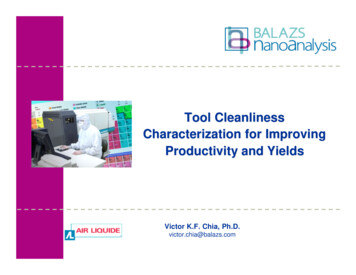
Preparation of the Silicon Wafer MediaFrom: http://www.ade.com/employment/silicon wafer.htmlWafer products are measured at various stages of theprocess to identify defects inducted by the manufacturingprocess. This is done to eliminate unsatisfactory wafermaterials from the process stream and to sort the wafersinto batches of uniform thickness and at a final inspectionstage. These wafers will become the basic raw material fornew integrated circuits. The following is a summary of thesteps in a typical wafer manufacturing process.Crystal Growth and Wafer Slicing ProcessSilicon Thermal PropertiesThermal Conductivity (solid) 1.412 W/cm-KThermal Conductivity (liquid) 4.3 W/cm-KSpecific Heat 0.70 J/g-KThermal Diffusivity .9 cm**2/sMelting Point 1683 KBoiling Point 2628 KCritical Temperature 5159 KDensity (solid) 2.33 g/cm**3Density (liquid) 2.53 g/cm**3Vapor pressureat 1050C 1e-7 Torrat 1250C 1e-5 TorrMolar heat capacity 20.00 J/mol-KThe first step in the wafer manufacturingprocess is the formation of a large, perfect silicon crystal. Thecrystal is grown from a ‘seed crystal’ that is a perfect crystal.The silicon is supplied in granular powder form, then melted ina crucible. The seed is immersed carefully into the crucible ofmolten silicon, then slowly withdrawn.Step 1: Obtaining the SandThe sand used to grow the wafers has to be a very clean and good form of silicon. For this reason not justany sand scraped off the beach will do. Most of the sand used for these processes is shipped from thebeaches of Australia.Step 2: Preparing the Molten Silicon BathThe sand (SiO2)is taken and put into a crucible and is heated to about 1600 degrees C – just above itsmelting point. The molten sand will become the source of the silicon that will be the wafer.Step 3: Making the IngotA pure silicon seed crystal is now placed into the molten sandbath. This crystal will be pulled out slowly as it is rotated. Thedominant technique is known as the Czochralski (cz) method.The result is a pure silicon cylinder that is called an ingot. Asdescription or a variant on the Czochralski method is available athttp://www.ioi.co.uk/tech/dera/p0526.htmThe Czochralski methodSeth BatesSJSU / Applied Materials / IISME-ETPpage 3
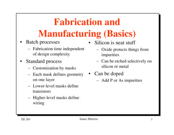
Examples of some completed ingotsAn epitaxial reactor.Growth of Epitaxial SiliconThis step is done to provide a good clean surface for later processing. If a layer of Silicon is grown ontothe top of the wafer using chemical methods then that layer is of a much better quality then the slightlydamaged or unclean layer of silicon in the wafer. Theepitaxial layer is where the actual processing will bedone.The diameter of the silicon ingot is determined by thetemperature variables as well as the rate at which theingot is withdrawn. When the ingot is the correctlength, it is removed, then ground to a uniformexternal surface and diameter.Each of the wafers is given either a notch or a flatedge that will be used later in orienting the wafer intothe exact position for later procedures. In these two figures you can see a notch (above) and flats. Flatsin this image are exaggerated for clarity.Step 4: Preparing the WafersAfter the ingot is ground into the correct diameter for the wafers, thesilicon ingot is sliced into very thin wafers. This is usually done with adiamond saw.A diamond saw for cutting wafersEach of these wafers will then go through polishing until they are very smooth and just the rightthickness (see Polishing Process, below).Thickness SortingSeth BatesSJSU / Applied Materials / IISME-ETPpage 4
Following slicing, silicon wafers are often sorted on an automated basis intobatches of uniform thickness to increase productivity in the next process step,lapping. During thickness sorting, the wafer manufacturer can also identify defecttrends resulting from the slicing process.Lapping & Etching ProcessesLapping removes the surface silicon which has been cracked or otherwise damagedby the slicing process, and assures a flat surface. Wafers are then etched in achemically active reagent to remove any crystal damage remaining from theprevious process step.Thickness Sorting and Flatness CheckingFollowing lapping or etching, silicon wafers are measured for flatness to identify and control defecttrends resulting from the lapping and etching processes. Wafers are also often sorted on an automatedbasis according to thickness in order to increase productivity in the next process step, polishing.Polishing ProcessPolishing is a chemical/mechanical process that smoothes the uneven surface left by the lapping andetching processes and makes the wafer flat and smooth enough to support optical photolithography.A wafer polishing machineWafers in storage traysFinal Dimensional and Electrical Properties QualificationThe wafers undergo a final test, performed in order to demonstrate conformance with customerspecification for flatness, thickness, resistivity and type. Process induced defect and defect trendinformation is used by the wafer manufacturer for yield and process management of the immediatelypreceding steps. Information regarding surface defects, such as scratches and particles, and defect trendinformation are used by the wafer manufacturer for yield and process improvement.Seth BatesSJSU / Applied Materials / IISME-ETPpage 5
Seth BatesSJSU / Applied Materials / IISME-ETPpage 6
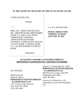
Silicon Wafer Processing StepsSemiconductor manufacturingfrom http://www.micron.com/resources/semi manufacture.htmToday, most integrated circuits (ICs) are made of silicon. Turning silicon intomemory chips is an exacting, meticulous procedure involving engineers,metallurgists, chemists and physicists. The first step from silicon to circuit is the creation of a pure,single-crystal cylinder or ingot of silicon six to eight inches in diameter. These cylinders are sliced intothin, highly polished wafers less than one-fortieth of an inch thick. Micron uses six- and eight-inchwafers. The circuit elements (transistors, resistors, and capacitors) are built in layers on the silicon wafer.Hundreds of memory chips are etched onto each wafer.Pure single-crystal cylinders of silicon are sliced into thin, highly polished wafers less than one-fortiethof an inch thick. Hundreds of memory chips are etched onto each wafer, while for processor chips,perhaps only ten to 50 devices will fit on one wafer.Most chip designs are developed with the help of computersystems or computer-aided design (CAD) systems. Circuits aredeveloped, tested by simulation, and perfected on computersystems before they are actually built. When the design iscomplete, glass photomasks are made—one mask for each layer ofthe circuit. These glass photomasks are used in a process calledphotolithography.FabricationSemiconductor memory chips are manufactured in cleanroom environments because the circuitry is sosmall even tiny bits of dust can damage it. Class 1 and class 10 cleanrooms are typical. In a class 1cleanroom, there is no more than 1 particle of dust in a cubicfoot of air. In comparison, a clean, modern hospital has about10,000 dust particles per cubic foot. The air inside acleanroom is filtered and recirculated continuously, andemployees wear special clothing such as dust-free gowns,caps, and masks to help keep the air particle-free.The figure at the right shows a modern semiconductor etchmachine. At the top left is the wafer handling system, whichaccepts wafers from the factory materials handling system,aligns them for processing in the etch machine, and movesthem into the main part of the machine. While this systemnormally operates at atmospheric pressure, it is usually at aSeth BatesSJSU / Applied Materials / IISME-ETPpage 7
Class 10 clean room level. When wafers move into the process part of the machine, they are containedin a vacuum, with extremely low particle contamination levels (Class 1). Even the smallest particle canruin an entire wafer, with a large number of integrated circuits affected, and costing hundreds orthousands of dollars.The large circular part in the center of the machine is a transfer area, which moves the wafers betweenprocess chambers. The machine shown has four process chamber locations, each one of which can beindividually configured depending on the process that is desired.After processing, the wafers are moved back into the materials handling system and returned to thefactory floor. For further processing. A single wafer may have to undergo many succesive process stepsto achieve the complexlayers of conductor,semiconductor, andinsulating material neededto produce the desiredcircuitry. This process isdescribed below, inoutline first, then in moredetail.Layers on a semiconductor device.Process Steps Outline!Diffusion. A layer of material such as oxide is grown or deposited onto thewafer.!Coat / Bake. The resist, a light sensitive protective layer, is applied andcured in place.!Align. A reticule is positioned over the wafer. Ultraviolet light shinesthrough the clear portions of the reticule exposing the pattern onto thephotosensitive resist.!Develop. The resist is developed and unwanted resist is washed away.!Dry Etch. Dry etch removes oxide not protected by resist.!Wet Etch and Clean. The remaining resist is removed in wet etch to reveal the patterned oxide layer.Then the wafer is cleaned. The process is repeated up to 18 times to create the various layers necessary foreach part's circuitry.Process Steps DetailsIn this sterile environment, the wafers are exposed to a multiple-step photolithography process that isrepeated once for each mask required by the circuit. Each mask defines different parts of a transistor,capacitor, resistor, or connector composing the complete integrated circuit and defines the circuitrypattern for each layer on which the device is fabricated.Seth BatesSJSU / Applied Materials / IISME-ETPpage 8
At the beginning of the production process, the bare silicon wafer is covered with a thin glass layerfollowed by a nitride layer. The glass layer is formed by exposing the silicon wafer to oxygen attemperatures of 900 degrees C or higher for an hour or more, depending on how thick a layer is required.Glass (silicon dioxide) is formed in the silicon material by exposing it to oxygen. At high temperatures,this chemical reaction (called oxidation) occurs at a much faster rate.PhotolithographyNext, the wafer is uniformly coated with a thick light-sensitiveliquid called photoresist. The coating is applied while thewafer is spinning.Portions of the wafer are selected for exposure by carefullyaligning a mask between an ultraviolet light source and thewafer. In the transparent areas of the mask, light passesthrough and exposes the photoresist.Direct Wafer Stepping (DWS)In this method the mask is quite a bit fartheraway from the wafer and through a series ofoptics the image is placed onto the wafer. Themain advantage of this method is that the maskcan be quite a bit larger then the final pattern andthrough optical and mechanical manipulations abetter resolution can be exposed onto thephotoresist. This method is currently the numberone method used in industry.Photoresist hardens and becomes impervious toetchants when exposed to ultraviolet light. Thischemical change allows the subsequent developer solution to remove the unexposed photoresist whileleaving the hardened, exposed photoresist on the wafer.Etching the Wafer SurfaceThe etching process is used immediately after photolithography to etch the unwanted material from thewafer. This process is not selective and that is why the pattern had to be traced onto the wafer usingphotoresist. There are two main methods of etching, wet etching and dry etching. This leaves a patternon the wafer in the exact design of the mask. The hardened photoresist is then removed (cleaned) withanother chemical.Seth BatesSJSU / Applied Materials / IISME-ETPpage 9
Wet EtchingWet etching is done with the use of chemicals. A batch of wafers is dipped into a higly concentrated poolof acid and the exposed areas of the wafer are etched away. Wet etching is good in that it is fairly cheapand capable of processing many wafers quickly. The disadvantage is that wet etching does not allow thesmaller critical geometries that are needed for todays chips.Acid being poured onto a waferA closer look at acid and the wafer.Dry EtchingDry etching refers to any of the methods of etching that use gas instead of chemical etchants. Dry etchingis capable of producing critical geometries that are very small.Plasma EtchingPlasma etching uses a gas that is subjected to an intense electric field to generate the plasma state ofmatter. The electric field is produced with coils that are wrapped around the chamber and exposed to ahigh level RF source. There are two different versions of this type of etching based on the shape of thechamber used. One consists of a barrel type chamber where the wafers are placed sitting up while the gasis flowed over the wafers and out through an exhaust pipe. The second process uses a parallel platereactor. There are two plates that are used to give the gas the electric field rather than the coil that iswrapped around the barrel chamber. In plasma form, the gases used are very reactive, providing effectiveetching of the exposed surface. Plasma etching provides good critical geometry but the wafer can bedamaged from the RF radiation.Reactive Ion EtchingThis method works at a lower pressure and uses a combined physical and chemical method to etch thewafer.Ion MillingIon milling uses electric and magnetic fields to cause the plasma ions to form a beam that is used to dothe etching. This method is extremely accurate and has the ability to reach very small critical geometries.Seth BatesSJSU / Applied Materials / IISME-ETPpage 10
Anisotropic Etching vs. Isotropic EtchingIsotropic etching is a problem that results from chemical etching and some forms of dry etching. Theresult is that the etchant material will etch to the side (laterally) as well as straight down. This can causesome of the material under the patterned resist to be etched away, resulting in undercutting and poorimage accuracy. Anisotropic etching occurs in most forms of dry etching. In this process there is nolateral etching so an exact representation of the pattern is etched onto the wafer. Anisotropic etching ismore desirable because there can be problems in maintaining the desired electrical characteristics if thereis lateral etching as well as vertical etching.Implant / Masking Steps: Diffusion & Ion ImplantElectrical characteristics of selected areas on the developing integrated circuit are changed by implantingenergized ions (dopants) in the form of specific impurities into areas not protected by resist or otherlayers. The dopants come to rest below the wafer's surface, creating the positive and negative areas onthe wafer which encourage or discourage the flow of electrical current throughout the die. These basicsteps are repeated for additional layers of polysilicon, glass, and aluminum. Typical dopants include:!Boron!Arsenic!PhosphorousThese processes can be damaging to the wafer, so a heating process known as annealing is used to reduceany damage to the wafers.DiffusionDiffusion is done in a furnace with a flow of gas running over the wafers. This step, like etch, is notselective so the photoresist and patterning need to be done before this step. The best way to understandthe processes of this step is to imagine oxidation. Diffusion is very similar to oxidation except using adifferent gas other than oxygen.Ion ImplantationIon implantation is different from diffusion. Diffusion uses the natural state of gas going to where thereis no gas, while ion implantation shoots the desired dopant ions into the wafer. Ion implantation has beenbest equated with firing amachine gun into a wall.In this analogy the wall is thewafer and the bullets arethe ions. The maindisadvantage of ionimplantation is that it can onlyprocess a single wafer at atime while a diffusionchamber is capable ofhandling many wafers.Seth BatesSJSU / Applied Materials / IISME-ETPpage 11
The magnets used to control the ion beamA wafer handling tray in ion implantationDrive InThis is the next step after the ions have been placed into the wafer. In this step the wafer is heated tomake the ions go deeper into the wafer.AnnealingDue to the incredible damage that these processes (especially ion implantation) can cause to the wafer anadditional stage of heating is required. During this final stage the wafer is heated so that the crystallattice structure of the wafer will repair itself.The finished wafer is an intricate sandwich of n-type andp-type silicon and insulating layers of glass and siliconnitride.All of the circuit elements (transistor, resistor, andcapacitor) are constructed during the first few maskoperations. The next masking steps connect these circuit elements together.An insulating layer of glass (called BPSG) is deposited and a contact mask is used to define the contactpoints or windows of each of the circuit elements. After the contact windows are etched, the entire waferis covered with a thin layer of aluminum in a sputtering chamber. The metal mask is used to define thealuminum layer leaving a fine network of thin metal connections or wires.The entire wafer is then covered with an insulating layer of glass and silicon nitride to protect it fromcontamination during assembly. This protective coating is called the passivation layer. The final maskand passivation etch removes the passivation material from the terminals, called bonding pads. Thebonding pads are used to electrically connect the die to the metal pins of the plastic or ceramic package.While still on the wafer, every integrated circuit is tested and functional and nonfunctional chips areidentified and mapped into a computer data file. A diamond saw then cuts the wafer into individualchips. Nonfunctional chips are discarded and the rest are sent on to be assembled into plastic packages.Seth BatesSJSU / Applied Materials / IISME-ETPpage 12
Die Attach / Wire BondBefore the die are encapsulated, they are mounted on to lead frames, andthin gold wires connect the bonding pads on the chip to the frames tocreate the electrical path between the die and lead fingers.Product samples are taken out of the normal product flow forenvironmental and reliability assurance testing. These quality assurancetest push chips to their extreme limits of performance to ensure highquality, reliable die and to assist engineering with product and processimprovements.EncapsulationDuring Encapsulation, lead frames are placed onto mold plates and heated. Molten plastic material ispressed around each die to form its individual package. The mold is opened, and the lead frames arepressed out and cleaned.Lead Finish / Trim and FormElectroplating (illustrated at left) is the next process where the encapsulated lead frames are "charged"while submerged in a tin/lead solution. The tin/lead ions are attracted to the electrically charged leadscreate a uniform plated deposit which increases the conductivity and provides a clean consistent surfacefor surface mount applications.In Trim & Form, lead frames are loaded into trim-and-form machines where the leads are formed step bystep until finally the chips are severed from the frames. Individual chips are then put into anti-static tubesfor handling and transportation to the test area for final testing.Various Memory Chip Packaging (the thinnest being the most recent)The various positions and shapes of the leads and the package size and shape depend on the finalapplication and the customer's packaging requirements.Seth BatesSJSU / Applied Materials / IISME-ETPpage 13
Final Testing / ShippingEach memory chip is tested at various stages in the manufacturing process to see how fast it can store orretrieve information, including the high temperature burn-in in Micron's proprietary AMBYX ovenswhich test the circuitry of each chip, ensuring the quality and reliability. This monitored burn-in providesfeedback throughout the process, allowing identification and correction of manufacturing problems.The completed packages are inspected, sealed, and marked with a special ink to indicate product type,date, package code, and speed. The finished goods area ships the chips to computer, peripheral,telecommunications, and transportation customers throughout the world.In the last 30 years semiconductors have become virtually indispensable in many aspects of daily life.Even people who do not own or use a computer are likely to use semiconductor memory in one way oranother. Many of the fantastic capabilities of our modern world are possible thanks to the semiconductormemory chip.Seth BatesSJSU / Applied Materials / IISME-ETPpage 14
Step 3: Making the Ingot A pure silicon seed crystal is now placed into the molten sand bath. This crystal will be pulled out slowly as it is rotated. The dominant technique is known as the Czochralski (cz) method. The result is a pure silicon cylinder that is called an ingot. As descripti