Transcription
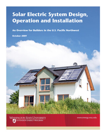
SOLAR PV SYSTEM DESIGNA solar PV system design can be done in four steps: Load estimationEstimation of number of PV panelsEstimation of battery bankCost estimation of the system.Base condition:2 CFLs(18 watts each),2 fans (60 watts each) for 6hrs a day. The total energy requirement of the system (total load) i.e Total connected load to PV panelsystem No. of units rating of equipment 2 18 2 60 156 watts Total watt-hours rating of the system Total connected load (watts) Operating hours 156 6 936 watt-hours Actual power output of a PV panel Peak power rating operating factor 40 0.75 30 watt The power used at the end use is less (due to lower combined efficiency of the system Actual power output of a panel combined efficiency 30 0.81 24.3 watts (VA) 24.3 watts Energy produced by one 40 Wp panel in a day Actual power output 8 hours/day (peak equivalent) 24.3 8 194.4 watts-hour Number of solar panels required to satisfy given estimated daily load : (Total watt-hour rating (daily load)/(Daily energy produced by a panel) 936/194.4 4.81 5 (round figure) Inverter size is to be calculated as : Total connected load to PV panel system 156 watts Inverter are available with rating of 100, 200, 500 VA, etc. Therefore, the choice of the inverter should be 200 VA.COST ESTIMATION OF A PV SYSTEM(a) Cost of arrays No. of PV modules Cost/Module 5 8000 (for a 40 Wp panel @ Rs.200/Wp) Rs.40000(b) Cost of batteries No. of Batteries Cost/Module 1 7500 Rs.7500
(c) Cost of Inverter No. of inverters Cost/Inverter 1 5000 1 5000 Rs.5000Total cost of system A B C 40000 7500 5000 Rs.52500[Additional cost of wiring may be taken as 5% of total system cost]ASSUMPTIONS TAKEN FOR DESIGN: Inverter converts DC into AC power with efficiency of about 90%. Battery voltage used for operation 12 volts The combined efficiency of inverter and battery will be calculated as :combined efficiency inverter efficiency battery efficiency 0.9 0.9 0.81 81% Sunlight available in a day 8 hours/day (equivalent of peak radiation. Operation of lights and fan 6 hours/day of PV panels. PV panel power rating 40 Wp (Wp, meaning, watt (peak), gives only peak poweroutput of a PV panel) A factor called „ operating factor‟ is used to estimate the actual output from a PV module.[The operating factor between 0.60 and 0.90 (implying the output power is 60 to 80%lower than rated output power) in normal operating conditions, depending ontemperature, dust on module, etc.]
DESIGN OF BIOGAS PLANTBiogas system design for cooking for a family of six members is considered here. The system designincludes the estimation of total gas required, amount of feedstock (or dung), required and the numberof animals required to have feedstock of a given amount.Following assumptions are made for the design:About 350-450 litres of biogas required per day per person for cooking (in engine about 450litres/hp/hour of biogas is required)Average production of dung per animal per day: Cow– 10 kg/day Bullock – 14 kg/day Buffalo – 15 kg/dayOther biomass night soil, sugar cane bagasse, maize straw, etc. can also be used) 1000 litres of gas is equivalent to 1 m3 of gas. Average gas production from dung is about 40 litres/kg of fresh dung. Retention period of dung slurry in digester is 50 days.AMOUNT OF GAS REQUIRED PER DAYI.II.III.IV.Number of family members 6 (adult). Considering 400 litre/day/person for cooking, totalgas required 6 400 2400 litres/day or about 2.4 m3 gas/day.Number of animals required to fulfil daily gas requirement Amount of gas produced from akg of fresh dung 40 litre/kg.Total amount of dung required Total gas required/Gas per kg of dung 2400/40 60 kg.Thus, in order to have 60 kg of dung no. of cows required in order to have 60 kg of dungno. of cows required 60/10 6 cows.DESIGN OF DIGESTER AND GAS HOLDERIn order to make slurry, water should be added to equal amount of dung. Total mass of slurry – Dung Water 60 60 120 kg.Volume of slurry per day (specific gravity of slurry is about 1090 kg/m3) Total mass of slurry/Specific gravity 120/1090 0.11 m3Retention period of slurry 50 days. Total volume of the digester per day volume of slurry retention period 0.11 50 5.5 m3 6 m3.Dimensions of the digester : Depth to diameter ratio should be between 1 and 1.3Gas holder tank dimension : The volume of the gas holder tank should be about 60% of theper day gas volume.Various possible costs incurred in manufacturing of a biogas plant is given below:
ComponentCapital cost (Rs.)1. Gas holder and frame55002. Piping and stove17503 .Civil engineering constructionTotal cost of biogas plant1200019250SAVING DUE TO USE OF BIOGAS PLANTAssuming that biogas is replacing the use of LPG in a household, following calculations can be doneto calculate the amount savings. The amount of LPG required is about 2kg/per person/month Total LPG required for 6 people for a month is 6 2 12 kg/month Cost of LPG per kg is about Rs. 24. Total cost of LPG (if used in place of biogas) 12 24 Rs.288 per month (this amount ismonthly saving.) Total yearly savings 288 12 Rs.3456 per year Therefore, the simple payback period is Total cost of biogas plant/yearly savings 19250/3456 5.5 years
ESTIMATION OF REQUIRED WIND TURBINE POWER RATINGAssume that annual energy requirement of an industry is 20000 kWh ,we calculate that what will bethe size of wind turbine that is required to be installed to meet the energy requirement.Following assumptions are taken into account for estimation: Annual energy requirement – 20000 kWh Propeller type wind machine is used Coefficient of performance – 0.40 Wind speed at 15 metre height is 5 metre/sec (if the turbine hub is placed at the heightother than 15 metre, the wind speed should be estimated as shown in „vertical‟ windspeed variation section‟. Density of air – 1 kg/m3 Capacity factor – 0.30 (i.e. 30% of the time, wind machine is producing energy atrated power) Number of hours in a year 8760 hours.The power density of wind (power per unit area) ½ air density (velocity)2 0.5 1 (5 5 5) 62.5 watt/m.Actual power density that will be converted to useful energy Cp transmission loss generator lossConsidering losses Coefficient of performance Cp 0.40 Transmission losses (rotor to generator) 0.90 Generator losses 0.90Overall loss factor 0.40 0.90 0.90 0.324 Actual power density 62.5 0.324 20.25 W/m2 Annual energy density (useful) power density number of hours per year 20.25 8760 177.39 kWh/m2
The rotor size and turbine power rating estimation:Total annual energy required20000 -------------------------------------- ------------- 112.75 m2 .Useful energy density177.39 Radius of the rotor blade, (R)πR2 112.75R 5.91 metre. Power rating of the turbine Actual power density area of the rotor 20.25 112.75 2.28 kWActual rated power of the turbine rating should be power rating / capacity factor 2.28/0.30 7.6 kW 8KwThus, a 8 kW rated power wind turbine will provide desired annual energy under given situation.The cost of a wind turbine of per kW basis runs between Rs.30000 and Rs.50000. For the abovecalculation a 8 kW wind turbine would cost about 8 40000 – Rs.320000.Assumption made:[The above power rating is based on the assumption that wind speed of 5 metre/sec will be availablethroughout the year, 8760 hours, which is not the case, therefore we have taken the capacity factorinto account.]
ORGANISATION OF POWER SECTOR IN INDIAThe subject Power is the concurrent list of Indian Constitution. As such, the responsibility of powerdevelopment lays both with the central and state governments.In the central government, the „Ministry of Energy‟ looks after the development of electricenergy and lays down policies regarding generation, transmission, distribution and conservation ofelectric energy. Under the Electric Supply Act, the Central electricity Authority (CEA) and StateElectricity Boards have been set up.The functions of CEA are :(1) Development of national power policy, formulations and coordination of plans of powerdevelopment,(2) Techno-economic appraisal of projects, monitoring the implementation of projects,(3) Ensuring efficient operation of power system, arbitration in certain matters promotion andcoordination of research and design activities in the power sector, providing assistance to stategovernments and electricity boards, collection and publication of statically information relating topower supply industry.(4) Design and consultancy services and development of training program for power engineers.(5) Regional electricity boards were set up in 1964 in each of the five regions for development ofintegrated operation, initially between the states of the region with the ultimate aim of forming aNational grid. The five regional electricity boards are :1. Northern Regional Electricity Board covering Haryana, Himachal Pradesh, Jammu &Kashmir, Punjab, Rajasthan, UP Uttaranchal and Delhi, (head office New Delhi)2. Western Regional Electricity Boards covering Gujrat, Madhyapradesh Chhatisgarh,Maharastra, Goa, Daman, Diu, Dadra and Nagar Havellu (head office Bombay).3. Southern Regional electricity boards covering Andra Pradesh, kanrantaka, Kerala, TamilNadu, and Pondicherry (head Office Bangalore)4. Eastern Regional boards covering Bihar, Jharkhand, Orissa West Bengal ( head officeCalcutta)5.North Eastern Regional Electricity Boards covering Assam, Manipur Meghalaya, Nagaland,Tripura, Arunachal Pradesh and Mizoram (head office Shillong).Regional load dispatch centres have been established to coordinate the activities of state loaddispatch Centre so as to ensure optimum utilization of generation and transmission facilities in theregions. State Electricity Boards were set up in 18 states. These boards are mainly responsible forgeneration, transmission and distribution of electricity in their respective states. These boards aremainly responsible for generation, transmission and distribution of electricity in their respectivestates.In the remaining states viz. Manipur, Tripura, Sikkim, Nagaland, Goa, Mizoram,Arunachal Pradesh and all Union territories, there are no electricity boards and the generation,transmission and distribution of electricity is looked after by state Electricity Departments. Now the
state electricity boards have been converted into corporations. The Central Government has also setup many public sector undertakings for planning and setting up power projects. The national Thermal Power Projects corporation (NTPC) was set up in 1975 for planning,execution and operation of large pithead power stations and associated transmissionnetworks. NTPC has set up many super thermal power station at Singruauli (UP), Korba (MP),Ramagundem (AP), Faraka (WB), Vindhayachal (MP) and Rihand (UP). The 2000 MW units at Korba and some 219 MW units at other plants have beencommissioned. 500 MW units at Rihand and three 500 MW at Farakka have also beencommissioned. The National Hydro Power Corporation (NHPC) was set up in 1975 to construct centralsector hydroelectricity projects, transmission lines and ancillary works. NHPC has set upBaira Siul and Salal hydroelecricty project (J& K), Chamera Hydro Project (HP) andDeighat Hydroelectric Project ( Nepal). The national Project and construction Corporation was set up in 1957 as joint venture ofcentral and state Governments for the execution of multipurpose river valley projects, powerprojects and other project and other heavy engineering projects. The north Eastern Power Corporation (NEEPCO) was set up in 1976 to develop and set uppower projects in north-eastern region. It is setting up 150 MW Kopili hydroelectric project. The Damodar Velly Corporation (DVC) was set up in 1948 for proper development ofDamodar Vally in Bihar and West Bengal. The Bhakra Beas Management Board (BBMB) was established in 1966 to manage Bhakraand Beas projects in Northern region. The Nuclear Power Corporation was set up in 1987 to look after the development of nuclearpower. A target of 20 GW of nuclear capacity by the year 2025 has been set. The Rural electrification Corporation (REC) was set up in 1969 to promote and financialrural electrification projects in the country. A large number of villages have been electrifiedin each state and some states have achieved 100% rural electrification. Power Grid Corporation of India (earlier known as National Power TransmissionCorporation) was set up in 1990 to look after the development and operation of EHVtransmission system in the country. The ministry of Non-conventional energy sources looks after and promotes the research anddevelopment of new and renewable sources of energy.
APPLICATION OF NON-CONVENTIONAL ENERGIES THROUGHWBREDAThe West Bengal Renewable Energy Development Agency (WBREDA) continues to implement oneof the country‟s largest broad-spectrum programmes covering the whole range of Renewable Energy(RE) sources. The Programme cover providing of electricity to remote unelectricfied rural areas ofthe state which are mostly located in Islands of Sundarbans, Forest areas of West Midnapur andBankura, hilly areas of Darjeeling.The state of West Bengal is generating about 30 MW power through primary fuel – biomass,wind, solar, mini hydel and a small portion of diesel.MAJOR SOLAR ENERGY APPLICATIONS OF WBREDA Installation of Solar Water HeatersBuilding Integrated Photovoltaic SystemEnergy Recovery from Municipal Solid WasteInstallation of Solar Street Light in city roadsOver 50 MW of Renewable power generation capacities have been added in the state of West Bengalso far. More than half a million people in the remote areas of the State are enjoying the benefits ofelectricity which is highest in the country.On an average, West Bengal receives Solar Energy to the t
SOLAR PV SYSTEM DESIGN A solar PV system design can be done in four steps: Load estimation Estimation of number of PV panels Estimation of battery bank
