Transcription
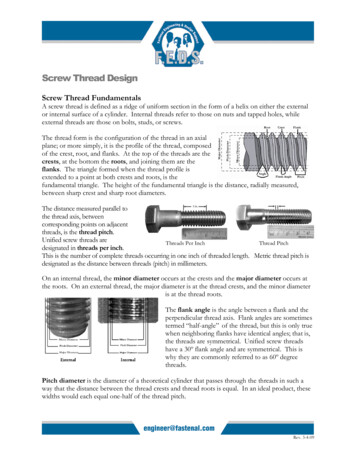
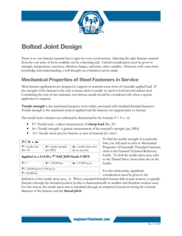
Bolted Joint DesignThere is no one fastener material that is right for every environment. Selecting the right fastener materialfrom the vast array of those available can be a daunting task. Careful consideration must be given tostrength, temperature, corrosion, vibration, fatigue, and many other variables. However, with some basicknowledge and understanding, a well thought out evaluation can be made.Mechanical Properties of Steel Fasteners in ServiceMost fastener applications are designed to support or transmit some form of externally applied load. Ifthe strength of the fastener is the only concern, there is usually no need to look beyond carbon steel.Considering the cost of raw materials, non-ferrous metals should be considered only when a specialapplication is required.Tensile strength is the mechanical property most widely associated with standard threaded fasteners.Tensile strength is the maximum tension-applied load the fastener can support prior to fracture.The tensile load a fastener can withstand is determined by the formula P St x As. P Tensile load– a direct measurement of clamp load (lbs., N)St Tensile strength– a generic measurement of the material’s strength (psi, MPa).As Tensile stress area for fastener or area of material (in2, mm2)P St x AsP tensile load(lbs., N)St tensile strength(psi, MPa)As tensile stress area(sq. in, sq. mm)Applied to a 3/4-10 x 7” SAE J429 Grade 5 HCSP ?St 120,000 psiAs 0.3340 sq. inTo find the tensile strength of a particularbolt, you will need to refer to MechanicalProperties of Externally Threaded Fastenerschart in the Fastenal Technical ReferenceGuide. To find the tensile stress area, referto the Thread Stress Areas chart also in theGuide.P 120,000 psi x 0.3340 sq. inP 40,080 lbs.For this relationship, significantconsideration must be given to thedefinition of the tensile stress area, As. When a standard threaded fastener fails in pure tension, it typicallyfractures through the threaded portion (as this is characteristically its smallest and therefore weakest area).For this reason, the tensile stress area is calculated through an empirical formula involving the nominaldiameter of the fastener and the thread pitch.Rev 3-4-2009
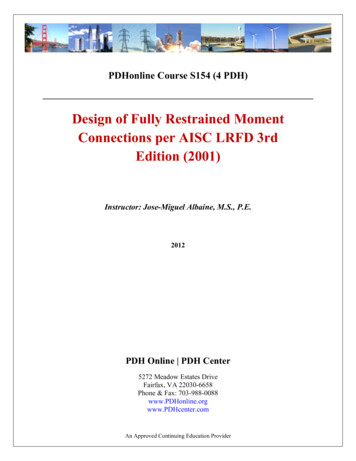
As the fastener approaches the maximum strength of the threaded portion, it will permanently deform.To avoid this risk, most carbon or alloy steel bolts have a defined proof load, which represents the usablestrength range for that particular fastener. By definition, the proof load is an applied tensile load that thefastener must support without permanent deformation. In other words, the bolt returns to its originalshape once the load is removed.The relationship between tension and boltstretch can be observed on a Tensile StressStrain Diagram. To the left is the stresselongation curve. Steel possesses a certainamount of elasticity as it is stretched. Thus, abolt that is properly tensioned should befunctioning in the elastic range (as viewedon the Diagram). If the load is removed andthe fastener is still within the elastic range, thefastener will always return to its originalshape.However, if the load applied causes thefastener to exceed its yield point, it enters theplastic range. At this point, the steel is nolonger able to return to its original shape if theload is removed. The yield strength is thepoint at which a specified amount of permanent deformation occurs. If we would continue to apply aload, we would reach a point of maximum stress known as the ultimate tensile strength. Past this point,Rev 3-4-2009
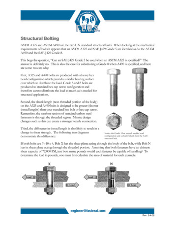
the fastener continues to neck down and elongate further with a reduction in stress. Additionalstretching will ultimately cause the fastener to break at the tensile point.Harder, higher tensile strength fasteners, such as the A574 tend to be less ductile than the softer lowerstrength fasteners. Although they have higher tensile strength, the overall length of the strain curve isoften decreased.Shear strength is defined as the maximum load thatcan be supported prior to fracture, when applied at aright angle to the fastener’s axis. A load occurring inone transverse plane is known as single shear. Doubleshear is a load applied in two planes where the fastenercould be cut into three pieces.For most standard threaded fasteners, shear strength isnot specified even though the fastener may becommonly used in shear applications. While sheartesting of blind rivets is a well-standardized procedurethat calls for a single shear test fixture, theDouble Shear Throughshear testing technique for threaded fasteners is Threadsnot as well designed. Most procedures use a(½-13 SAE J429 Grade 8)double shear fixture, but variations in the testfixture designs cause a wide scatter in measuredshear strengths (i.e., the variations in testprocedures produce non-standard results).To determine the shear strength of thefastener, the total cross-sectional area of theshear plane is important. For shear planesthrough the threads, we could use the threadroot area. There are two possibilities forapplied shear load (as illustrated below). Onepossibility is that the shear plane occurs in thethreaded portion of the bolt. Since shearstrength is directly related to the net sectionalarea (i.e.: the amount solid bolt material in thediameter), a narrower area will result in lowerbolt shear strength. To take full advantage ofstrength properties the shank of the bolt bodyshould be within the shear planes. Toillustrate, consider the difference in shearstrength between the two Grade 8 bolts on theprevious page; one with the threads in theshear plane, the other with the shank in the½-13 Thread Root Area:0.126 sq-in60% of Tensile Strength:90,000 PSIDouble Shear 2 x 0.126 sqin x 90,000 PSIDouble Shear 22,680 lbs.Double Shear Through Body(½-13 SAE J429 Grade 8)Minimum Body Area 0.191 sqin60 % of Tensile Strength:90,000 PSIDouble Shear 2 x 0.191 sq-inx 90,000 PSIDouble Shear 34,380 lbs.Rev 3-4-2009
shear plane.When no shear strength is given for common carbon steels with hardness up to 40 HRC, 60 % of theultimate tensile strength of the bolt is typically used as acceptable shear strength. Note: the shear strengthmust fall within the constraints of a suitable safety factor. This formula should only be used as anestimation.A fastener subjected to repeated cyclic loads can break suddenly and unexpectedly, even if the loads arewell below the strength of the material. The fastener fails in fatigue. Fatigue strength is the maximumstress a fastener can withstand for a specified number of repeated cycles prior to its failure.Torsional strength is a load usually expressed in terms of torque, at which the fastener fails by beingtwisted off about its axis. Self-tapping screws and socket set screws require a torsional test to ensure thatthe screw head can withstand the required tightening torque.Other Mechanical PropertiesHardness is a measure of a material’s ability to resist abrasion and indentation. For carbon steels, Brinelland Rockwell hardness testing can be used to estimate tensile strength properties of the fastener(occasionally Vickers). For more information about these hardness tests and their corresponding scales(e.g.: HRC, HRB, etc.) see the glossary.Ductility is the ability of a material to deform beforeit fractures. A material that experiences very little orno plastic deformation upon fracture is consideredbrittle (e.g.: SHCS). A reasonable indication of afastener’s ductility is the ratio of its specified minimumyield strength to the minimum tensile strength. Thelower this ratio the more ductile the fastener will be.Toughness is a materials ability to absorb impact orshock loading. Impact strength toughness is rarely aspecification requirement. Besides various aerospaceindustry fasteners, ASTM A320 Specification for AlloySteel Bolting Materials for Low-Temperature Service is one of the few specifications that require impact testing oncertain grades.Joint DesignLoads can be applied to bolted joints in a number of different ways,each of which produces unique effects on the joint. These effectsresult from the way the joint is loaded, as well as how the jointresponds to the load. Some of the various load types include tensile,shear and bending. The type of bolted joint derives its name from theexternal load applied to the joint.Rev 3-4-2009
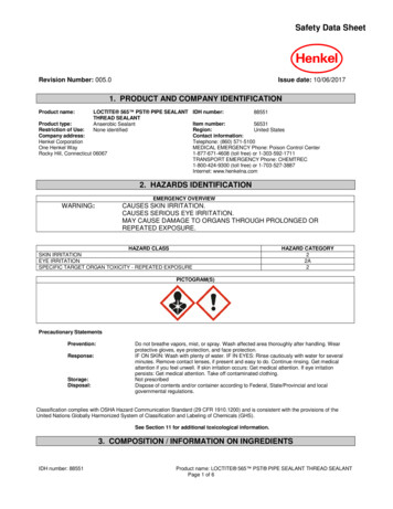
A tension joint, as illustrated in the photo, is affected by loads that try to pull the joint apart. The forceson the joint and those on the bolts are roughly parallel to the axes of the bolts. All tensile forces try tostretch and/or separate the joint. The tension load, no matter how small, will add to the stress in the boltand/or partially relieve the joint.The bolts in a tension joint must act like clamps. The tightening of the bolt and nut produces a tensilepre-stress, which is approximately equal to the compressive stress introduced in the joint material. Thebehavior and life of the joint depends on how tightly the bolts clamp and how long they can maintaintheir preload.Proper amount of tensioning of the bolts is vital. With too little clamping force, the joint may loosen. Ifthe joint is exposed to cyclical loads, too little clamping force can shorten the bolt’s fatigue life. Too muchclamping force can also cause severe problems. By over-tightening the bolt, one may exceed the proofload of the bolt. Even if the bolt does not fail during assembly, it may later break under the externaltensile load. Over-tightening of the bolt can also encourage the advancement of hydrogen embrittlementor stress corrosion cracking. The joint members can also be damaged or warp from too much clampforce.The clamping force created during tightening stretches the bolt similar to a spring. A similar analogy canbe made for the joined materials, except they are compressed like aspring during assembly. These “springs” exert a clamping forcethat will remain only as long as the bolts are stretched. Any appliedservice load or condition, which relaxes the bolt or reduces theclamping force, will release some of the spring’s energy (i.e.: clampforce within the joint). This will increase the chances that the jointmay loosen or that the bolts may fail.A joint diagram may help illustrate what happens as we apply ourpreload and the effects of external loads. In “Bolted Joint Diagram1”, as the bolt is tightened, the bolt elongates ( B). Due to theinternal forces resisting the elongation, a tension force or preload isproduced (Fp). Notice the constant slope or straight-linerelationship between the force and elongation. Remember that thestress-strain curve (which is basically applied force-elongation) willbe constant or straight until the fastener begins to yield (elasticregion).The reaction force (the right hand side of the graph)is the clamp load of the joint being compressed. J represents the amount that the joint hascompressed. As is illustrated, J is smaller than B.These values represent the stiffness of eachcomponent (joint and bolt). Often a bolt will onlybe about 1/3 to 1/5 as stiff as the joint that it is beingused in. In this instance, our bolt tension isRev 3-4-2009
equivalent to the preload, which is equivalent to the joint compression. Or, to phrase it another way, thetension force on the bolt (Fb) is equal to the compression force on the joint (Fj), which is equivalent tothe preload (Fp). This will change with the application of an external load. Bolted Joint Diagram 1 isillustrating elastic bolt elongation and elastic joint compression in the axial direction.In “Bolted Joint Diagram 2”, an external tensile force (F) has been applied to the joint under the bolt headand nut. The addition of this force has reducedsome of the clamp force on the joint ( Fj) andapplied an additional force on the bolt ( Fb).Since the bolt and joint have a different stiffness, Fb will not be the same as Fj. Also, the boltwill further elongate (new B), and the jointcompression will be reduced (new J). Theincrease in length is equal to the increase inthickness of the joint.If the applied load (F) is allowed to increase, theclamp force acting on the joint will continue todecrease until the joint is fully unloaded, as can beseen in “Bolted Joint Diagram 3” ( J 0). Anyfurther increase in the applied force will result in a gapbetween the plates and the bolt sustaining all of theadditional force. In this case, the bolt or bolts arealmost always subjected to non-linear loadings frombending and shear forces. This quickly leads to bolt failure.This is only a fraction of the possible scenarios that can be examined through joint diagrams. There are anumber of other “real-life” factors, which may be impossible to predict, that allow the spring energy to belost in the assembled joint. These factors include (but are not limited to) different points of loading,creep, alternating external loads, stress relaxation (in some instances a relaxation of 10% to 20% iscommon), temperature, differential thermal expansion, and vibration.The overriding concern with the tension joint is its reliance on bolt tension or preload. If the clampingforce is not correct, the joint can fail in several ways; either by bolt fatigue, vibration loosening, stresscorrosion cracking or hydrogen embrittlement.A shear joint is one in which the applied loading is at rightangles to the fastener axis; that is, across the bolt shank. Shearjoint failure occurs when the joint members are slippedsideways past each other, and eventually cut the fastener.Rev 3-4-2009
With some shear joints; the ultimate joint strength depends only upon the shear strength of the bolts.This type of joint is referred to as a “bearing type” joint. The amount of tension created in the boltsduring assembly is relatively unimportant as long as the fastener is retained in the assembly. The jointmember is allowed to slip until the fasteners come into “bearing” and prevents further slip. The fastenerin this assembly is basically used as a pi
The tensile load a fastener can withstand is determined by the formula P St x As. . fastener to exceed its yield point , it enters the plastic range . At this point, the steel is no longer able to return to its original shape if the load is removed. The yield strength is the point at which a specified amount of permanent deformation occurs. If we would continue to apply a load, we would .