Transcription
Solar Tracking Structure DesignByHashem Bukhamsin, Angelo Edge,Roger Guiel, Dan VerneTeam 18Final Project ReportDocumentSubmitted towards partial fulfillment of the requirements forMechanical Engineering Design I – Fall 2013Department of Mechanical EngineeringNorthern Arizona UniversityFlagstaff, AZ 86011
Solar Power Tracking SystemTask 3-Power Point Tracking for Solar EnergyNorthern Arizona University (NAU)NAU College of Engineering, Forestry and Natural ScienceTeam SOLAREADY:Hashem Bukhamsin, Angelo Edge, Roger Guiel, Dan Verne, Majad Alharbi, Curt DuRocher,M. Ian Farnsworth, Michael Helland, Dustin SaggAdvisors:Dr. Tom Acker, Dr. David Scott and Professor Srinivas KosarajuMarch 21, 2014Task 3 Northern Arizona University 1
TABLE OF CONTENTSExecutive Summery . 3Task Identification . 3Full-scale Design . 4Bench-scale . 5Structural Analysis . 7Electrical hardware and Programming Design . 8Program Flow Chart . 11Cost Analysis . 11Waste Generation . 13Technical Evaluation . 13Legal, Health Issues and Economic Analysis . 15Conclusion . 15References . 16Task 3 Northern Arizona University 2
Executive SummeryCapturing and transforming the sun’s energy into electricity using photovoltaic collectiontechnology has been an ongoing research topic since the early 1960’s. In more recent years, thedemand has grown significantly for solar electric power generating systems thus causing theproduction to rise as well. With the demand for such technology higher efficiency and costeffectiveness has also become a requirement; simply put, higher output power generation isbeing required with a lower price tag. This demand has paved the way for research groupsworldwide to invest time and energy into developing more advanced technologies to suit theneeds of the ever growing clean energy industry.The challenge that is currently being posed within the Waste Management & EducationResearch Consortium (WERC) competition is to build off of current solar generationtechnologies in order to eliminate un-needed materials or tasks as well as designing the mostefficient autonomous power generation system possible. Fortunately, most recently designedesolar panels have already increased in power output while the cost has diminished compared totheir ten year old counterparts. What is now needed is a system that can utilize the maximumamount of sunlight hours in a day via a motorized tracking system while requiring as little poweras possible to run that tracking system.A Northern Arizona University mechanical and electrical engineering group hasdeveloped a system that meets the criteria of efficiency and cost effectiveness. By utilizing awide square support structure of lightweight stock steel tubing, lightweight brackets and joints,the physical structure provides mobility for storage or transportation as well as durability againstrough weather. The structure design also provides a manually adjusted North to South axis tooptimize the collection of sun light throughout the year based off of the suns changing latitude.This adjustable axis allows for more power generation throughout the year without needing topower a separate motor driven axis. Utilizing location as well as time of year based equationsthis axis can be manually adjusted every three months at a minimal cost of 400 per year to pay aprivate contractor to check the north to south angle assuming a pay of 20 per hour.The team of electrical engineers has designed a very simple tracking system for the eastto west axis by using basic components. Storing the produced energy within a rechargeable 12volt direct current (DC) deep cycle marine battery pack, the system allows for the powering of asmall scale micro-controller. This micro-controller regulates sensor responses as well aschronological based data in order to apply voltage to a actuator control arm which willphysically move the panel to the estimated location of the sun. These components come to anestimated cost of just over 300, not including the solar panel itself.By employing a low power micro-controller and a low power high torque actuator, theNorthern Arizona University Engineering team has designed an effective model for future solarpower generating systems. This model meets the desired capabilities of producing as muchoutput power as possible all while being affordable to the average consumer for small scaleapplications or even being deployed in a large scale solar farm power plant setting.Task IdentificationAccording to data collected by the Energy Information Administration, the United Statesis the 2nd largest energy consumer in the world with the majority of this energy being obtainedfrom fossil fuels. Because the world’s fossil fuels are limited, the use of renewable energy isbeing widely encouraged and explored.Task 3 Northern Arizona University 3
Solar energy is increasing in popularity throughout the world. Germany continues to leadthe world in solar power production while breaking its own records year after year [1] despite thenation’s nearly perpetual cloud cover. Saudi Arabia has pledged to reach a solar energy capacityof 41 Giga-Watts within the next 20 years [2]. There is a large potential for solar powerproduction in many locations throughout the United States and there are a number of means ofapplication. If utilized, many new industries could prosper within the United States as well asglobally all while decreasing the use of modern fossil fuels. Harnessing nearly infinite solarenergy could significantly subsidize power production methods which produce large amounts ofgreenhouse gases.Solar power production is usually accomplished using one of two methods. The firstmethod utilizes Photovoltaic (PV) cells to convert sunlight into an electric current by the meansof the photoelectric effect, in which a material absorbs electrons after receiving energy from alight source. A photovoltaic cell takes advantage of this effect by harnessing the electron flow inthe form of direct current electricity. This method is what team Solaready has decided to proceedwith for designing our tracking system. The second method of solar energy power production isthe Concentrated Solar Power (CSP) method. CSP generation uses mirrors to concentratesunlight into a specific spot. Unlike the PV method, the goal of the CSP method is to produceheat in order to drive a heat engine. Electricity is produced via a generator connected to the heatengine. This project will focus on the use of PV cells.Nationally the interest in green and solar technology has significantly risen and theindustry is demanding more efficient and cost effective systems. This project will improvecurrent environmentally friendly solar power technologies in order to increase efficiency anddecrease waste. The NAU engineering team was tasked to design a tracking system for aphotovoltaic solar power system, which will track the sun’s movements in order to collect asmuch of the sun’s energy as possible.The team must develop a solar tracking system that will demonstrate its costeffectiveness as compared to stationary PV system. A lifecycle analysis for the system must becompleted that includes the manufacturing, installation, maintenance and disposal of the solarsystem being proposed. The design must quantify the differences in power generation with andwithout the solar tracking device. To accomplish this project, the team generated a list ofengineering requirements to conduct research, and evaluate designs. Based on the engineeringanalysis, all the parts needed to build this design will cost a total of just under 700 not includingthe solar panel.Full-scale DesignAs modern solar fields become larger to produce more energy, certain parts of the singletracking system are eliminated to simplify the design and reduce the cost. The square base of thesolar tracker has been removed since the tracker does not need to be portable. Criticalcomponents, such as the bearings, linear actuator, elbows, conduit, PVC tubing, U bar, andvarious nuts and bolts have been retained. As a result, the cost of a single full scale field unit isless than the cost of single tracking unit.Implementing the tracker into a solar field can be done relatively easily. Each individualtracker is fixed into the ground using two vertical support poles. These poles are cemented inplace in order to provide additional stability when the panels are subjected to a wind load. Thissimplifies the overall design while maintaining the same level of accuracy and efficiency. Seeingas the design is simple to construct and does not require welding, each unit can be assembledquickly, drastically reducing the amount of time needed for the entire field. The remainder of theTask 3 Northern Arizona University 4
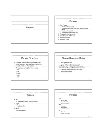
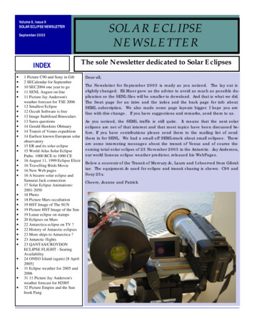
labor required is comprised of digging the necessary holes for the support poles and pouring theconcrete. A depth of six inches is sufficient to protect the panels from harsh winds.Panel array maintenance is comprised of three primary areas. The linear actuator used ineach panel has a warranty of two years, but has an estimated lifetime of 15-20 years after theinitial implementation into the solar field. It is suggested that all actuators are replaced at once inorder to reduce maintenance time and costs. Although the primary shaft does not experience highrotational speed, the bearings should be oiled at least once a year. This will ensure that trackingaccuracy and power consumption remains consistent across the entire array. Finally, the manualNorth-South axis of each tracker must be adjusted once a month in order to achieve the nearlymaximum power generation. This is the bulk of the maintenance workload, but it can beaccomplished relatively quickly by one person for smaller solar fields. Assuming that the solararray utilizes the same KC 130 panels as the competition, one person should be able to lift theframe and replace the PVC pipe without much difficulty. For larger, heavier panels, a minimumof two people will be required for each tracker.Figure 9: Single system (left). Full scale solar field (right).Bench-scaleThe base structure design has been modified for this system. It relies on a free standing,box structure, for easy mobility. This allows the solar panel to be moved to a different location,or even stored if needed. The design shown in Figure 1: Solar Tracking Frame, shows the base ofthe system which is made of square steel tubing on the bottom to prevent slippage. The rest ofthe structure is made out of circular cross sectional steel pipes and connected with purchasedbrackets of determined angle to hold the base together.Task 3 Northern Arizona University 5
Figure 1: Solar Tracking FrameThe support pole is connected to the triangle frame via adjustable pipe fixtures, shown inFigure 2 and Figure 3: Bracket 1 and 2. Because this tracker does not use the traditionalcemented in pole structure, attaching the support pole to the frame could only be achieved byusing these pre-made fixtures.Figure 2: Bracket 1Figure 3: Bracket 2With one of these brackets for each end, the exact angles of the frame can be adjusted toallow for a bigger tolerance. If a pipe is made too short, changing the adjustable tee, Figure 2:Bracket 1, is relatively easy to do. Changing the adjustable elbow, shown in Figure 3: Bracket 2,allows for different sun angles to be attained by the system.Task 3 Northern Arizona University 6
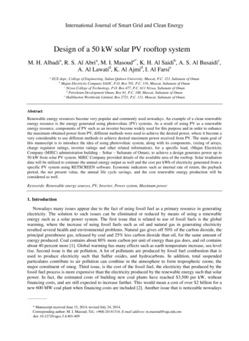
The solar panel support frame is made of stock metal to reduce weight. Because the solarpanels only weigh 24 pounds each, the metal should have no problem supporting the load as seenin the structural analysis section bellow. The panels are fixed to the frame with the use of smallbrackets that bolt into the solar panel support frame. By using these brackets, any size panels canbe put onto the structure with minimal adjustments. Two of the panels being used in the NewMexico State competition will fit on the solar panel support frame using four brackets. Twopillow bearings are bolted to the back of the solar panel support frame and are situated along thefixed axis of the base frame. The solar panel support frame is prevented from unwanted rotationthrough the use of the linear actuator. The linear actuator is connected to the back of the solarpanel support frame. The solar panel support frame connected to the base frame is shown inFigure 4.Figure 4: Final DesignThe actuator is an Eco-Worthy 12 volt, 18” stroke linear actuator. It is connected
The solar panel support frame is made of stock metal to reduce weight. Because the solar panels only weigh 24 pounds each, the metal should have no problem supporting the load as seen in the structural analysis section bellow. The panels are fixed to the frame with the use of small brackets that bolt into the solar panel support frame. By using these brackets, any size panels can