Transcription
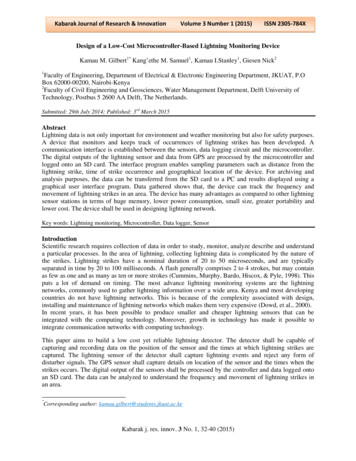
Design of a Low-cost Solar Tracking Photo-Voltaic (PV)Module and Wind Turbine Combination SystemS. Lakeou (1), E. Ososanya (1) , B.O. Latigo (2), W. Mahmoud (1)(1) Department of Electrical Engineering(2) Dean, School of Engineering and Applied SciencesUniversity of the District of ColumbiaI. IntroductionThis paper describes the design of a low cost, 0.9kW solar tracking photo-voltaic (PV) arraysystem as part of an undergraduate senior project. The solar tracking system is interfaced with a1kW wind turbine, a deep cycle battery storage system, a charge controller and an inverter. Solartracking is realized through “field” programmable complex digital circuit and alternatively with alow cost solar radiation sensing transducer consisting of green light emitting diodes (LED).Actuation of the panel tilt for azimuth tracking and rotation of the panel for solar tracking areoperated with a gear motor-based control system for adjusting the PV mount system’s position soas to collect maximum solar radiation. The gear motor controller module is built with state-ofthe-art, low-cost digital logic circuit with built-in flexibility to accommodate seasonal positionadjustments of the PV mounts. The design includes a computer remote access for monitoring thepower generation of the system. The system is configured for an insolation (solar radiation)condition specific to the location of the system at the University of the District of Columbia inWashington, DC, but could be easily configured for any other location.II. BackgroundAs depicted in Figure 1, the position of the sun with respect to that of the earth changes in acyclic manner during the course of a calendar year. Tracking the position of the sun in order toexpose a solar panel to maximum radiation at any given time is the main purpose of a solartracking PV system.
Figure 1 (a). Illustration of the summer and winter solsticesFigure 1 (b). Sun Path Diagram for 400 N Latitude During Winter and Summer SolsticesFor many years, several energy companies and research institutions have been performing solartracking for improving the efficiency of solar energy production. A variety of techniques ofsolar energy production used have proven that up to 30% more solar energy can be collectedwith a solar tracker than with a fixed PV system1. The cost of such systems is however still veryprohibitive for the average consumer or for a small-scale application. The current work showsthat a comparable system can be designed at a much lower cost particularly for academicinstitutions. In addition, the solar trackers currently available are generally not programmable forlocation flexibility. Moving a system from the northern hemisphere to the southern hemisphere,coupled with latitudinal and longitudinal position changes, can result in considerable designchanges to the tracker’s control circuitry.
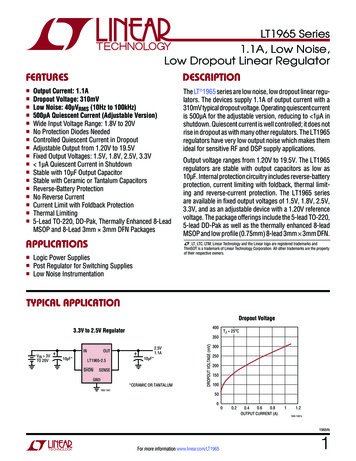
A typical solar tracking PV system must be equipped with two essential features:a) Azimuth tracking for adjusting the tilt angle of the surface of the PV array duringchanging seasons; andb) Daily solar tracking for maximum solar radiation incidence to the PV array.The Tilt Angle θ of a PV system required at any given time in the year can be expressed as afunction of the seasonal Sun’s Altitude φ as follows:Tilt Angle θ 900 – φSunSolarTrackingPV systemφθFigure 2. Tilt Angle θ of a PV arrayBefore the advent of solar tracking, fixed solar panels have been positioned within a reasonabletilt range based on the latitude of the location. A rule of thumb is to select a tilt angle of within 150 of the latitude depending on whether a slight winter or summer bias is preferred in thesystem. The PV array would face “true south” in the northern hemisphere and “true north” in thesouthern hemisphere. Note that the true south and the true north directions differ from themagnetic south and north direction usually obtained with a compass. Several reference tables arereadily available for making the appropriate tilt adjustments2. Solar tracking is best achievedwhen the tilt angle of the tracking PV array system is synchronized with the seasonal changes ofthe sun’s altitude and with the geographical insolation level for optimized solar tracking duringthe day3. The following three examples show the tilt angle and the insolation level (expressed inSun Hours/day) disparities between the geographic locations.Two locations from the northern hemisphere, Washington, DC and Addis Ababa, Ethiopia andone from the southern hemisphere, Cape Town, South Africa are selected for illustration. Notethat the average insolation for Addis Ababa is particularly high due to its proximity to theequator. The corresponding tilt angles and array orientations are summarized in Figure 3.
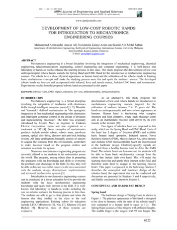
Washington, DCAverage Insolation: 4.23MonthSunAltitudeArrayTiltArrayPoints to:Addis Ababa, EthiopiaAverage Insolation: 5.84MonthSunAltitudeArrayTiltArrayPoints to:Cape Town, South AfricaAverage Insolation: 4.5MonthSunAltitudeArrayTiltArrayPoints 61SouthDEC5832SouthDEC8010NorthFigure 3. Tables showing the tilt angle disparity versus locationIII. Description of the Proposed Controller DesignIII.a. Field Programmable Controller Design SpecificationsThe programmable controller is expected to achieve the following:Two 24V, DC gear motors with selected gear ratio, control the rotation of a dual-axis PV arrayalong and the azimuth (tilt) tracking axis X, and the solar tracking axis Y as shown in Figure 4.The controller must interface with the DC motors through an H-Bridge structure. A complexprogrammable logic device (CPLD) feeds the H-Bridge with two signals, S for activating themotor and D for the direction of the rotor movement. The duration of the signal S is calculatedbased on the amount of rotation required for every angular step and on the gear ratio selected forthe gear motor, and the panel-to-motor transfer gear ratio.Initially, once the location is selected, the azimuth angle range is determined with a tilt angle θcalculator, and the angular step value is subsequently set. The total number of tilt steps is 12 (6 ineach direction) for covering the whole calendar year. During the course of the year, the arraywill be tilted around the X-axis progressively from June 21 to December 21 in one direction andfrom December 22 to June 20 in the opposite direction.For a simple tracking system, the daily solar tracking is achieved by rotating the array about thesolar tracking axis Y, by equal incremental angular steps ϕ 150. It is to be noted that thisproposed angular step does not reflect the actual angular step to be performed every month. Infact, the angular step varies from month to month and is location dependent. The programmablenature of the proposed design can easily account for these variations. The number of angular
steps covered during the day is determined seasonally in order to cover the maximum insolationfor the selected location. At the end of each day, the system is returned to its standby position.Hence, for a location such as Washington, DC, where the average insulation is 4.23 SunHours/Day, the number of steps will range from 12 per day on June 21 to 6 per day onDecember 21, with a respective start time of 6:00 am and 9:00 am. After December 22, thenumber of steps will increase by 1 on the proper day each month until the following June 21.Figure 4. Field Programmable Controller System DiagramThe following example illustrates the aforementioned tracking scheme:LocationRange ofArray TiltAngle θ( ) AzimuthTrackingAngular StepSolar TrackingAngular Stepon June 21 ϕNo. of SolarTracking Stepson June 21No. of SolarTracking Stepson Dec 21Washington, DC430430/6 701800/12 15012Start at 6:00 am6Start at 9:00 amIII.b. Functional Diagram and Implementation of the Field Programmable Controller CircuitThe electronic design is implemented with a complex programmable logic device (CPLD) fromXilinx, Inc. The selected CPLD is an 84-pin, Xilinx XC95108 with 2400 usable gates and 69user definable inputs and outputs.4 The design entry is performed with Xilinx’s IntegratedSoftware Environment ISE 8.1i design tool.5 The entry can be easily achieved either through aVHDL or with a Finite State Machine description of the circuit specifications. The designimplementation process includes the following steps: Schematic capture or finite state machine (FSM) description of the design using theIntegrated Software Environment (ISE) design environment of Xilinx or description of
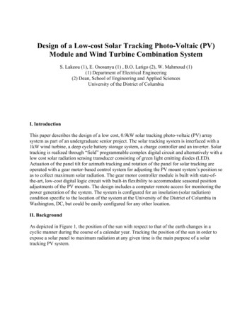
the design using the VHDL code from ISE. In the latter case, entities are defined forevery component of the design;Simulation of the circuit using Modelsim;Synthesis of the design; andProgramming of the XC95108 by downloading the design.The basic functional block of the circuit is described in Figure 5.PresetmonthTimer(1 second)MinuteCounterSolartrackingrange setHourCounterDayCounterMonthCounterMotor ControlSignal GeneratorMotor ControlSignal GeneratorSSDDFigure 5. Functional description of the CPLD (enclosed in the large box)The timer circuit consists of a 555 timer delivering a TTL signal of 1-second period. The presetmonth will be required if the system is installed in a month different that June. The system ispreset to start on June 21 at 6:00 am.III.c. PC-Based Controller DesignThe PC-based controller depicted in Figure 6 uses a low cost analog to digital (ADC) digital toanalog (DAC) interface circuit built at the University of the District of Columbia.6 The circuitinterfaces with an 8-point radiation sensor circuit. The radiation-to-electrical-voltage transduceris a green light emitting diode (LED), which generates an electric voltage of 1.67V under directsunlight. 8 LED’s are positioned on a semicircular support. The LED has a very acute directionalsensitivity to sunlight. A slight angular displacement, less than 100, of the LED from directsunlight results in a 20% decrease of the generated voltage.Solar tracking is achieved by software written in PC assembly language or other high levellanguage such as C to query the radiation level at the sensors and by sending digital signals Sand D to each H-bridge. Each LED is sensed periodically and appropriate S and D signals aresent to activate the appropriate DC motor to move the PV array to the direction of the highestlevel of voltage sensed.
The azimuth tracking follows the same scheme described for the field programmable design. Theangular steps are provided by sending out on the I/O digital bus, single digit signals for S and D,the width of the signal S is timed through software to correspond to the time required to providethe adequate rotation of the 24V DC motor in the selected direction.Figure 6. PC-Based Controller DiagramIV. Main Advantages of the Proposed Controller Design(a) Reduced Cost A cursory cost comparison between the proposed controller designapproaches and those currently available on the market shows that the controller circuitry costsaround 1,000.1 The cost excludes the price of the frame of the PV array and all otheraccessories, such as power supply for the gear motors. The typical price of a 12-module solartracking PV array is around 2,000.1Field Programmable ControllerComponentPrice ( )Xilinx XC95108 CPLD35H-bridge (2)40Timer circuit5Total80PC-Based Controller with Radiation SensorsComponentPrice ( )ADC/DAC board150Sensors7H-bridge (2)40Total197
With the exclusion of miscellaneous items, the cost involved in the proposed design issummarized in the above table. It is assumed that in most educational institutions, educationaldiscounts through university programs can be obtained for defraying the cost relative to designtools7 such as the Xilinx’s ISE 8.1i package.8(b) FlexibilityThe stand alone, field programmable controller design is perfectly suited toremote area applications. The CPLD can be re-programmed for any desired location. The arraycan therefore be a mobile power station with minimal design change. If properly designed toself power the 24V DC motors, the solar tracker system equipped with a field programmablecontroller can operate indefinitely with little supervision.The PC-based controller can be equipped with a power monitoring system. The PC can beinterfaced with a data acquisition board such as the NI-DAQ board from National Instrumentsand a simple LabView9 program can be written to monitor the power generated by the PV array.V. Application to a Solar PV and Wind Turbine Combination SystemThe sizing10 of the PV modules and the battery bank is done for generating 900W over a periodof 5 hours per day and 7 days per week. This requires 31500 WH per week and 1641 Amp Hoursper week. The power is needed for driving a Grundfos 11-SQL-2 pump which is rated at 30300V DC and 90-240V AC 50/60Hz.Wind Turbine H80 hv WhisperSolar Tracker/Wind Turbine Combo Power SystemIO 102 Switch BoxBattery BankEZ Wire system centerC40 Charge ControllerDR2424 InverterTransformerDC / AC Switch Box3-Phase AC24VTwo-axisSolar TrackerPV module12xBP4808-point Radiation SensorDC Power MonitorLabView-based48-210 V DCSolar Tracker Controller(PC-based & CustomProgrammable)11 SQL-2 PumpFigure 7. Solar Tracker with Wind Turbine Combo120V AC60Hz2.4KW
The system shown in Figure 7 comprises the following components: Whisper H80 hv (high voltage) wind turbine from Southwest WindpowerWattsun 125 AZ, dual-axis solar tracker with two 24V DC motorsXantrex/Trace C40 charge controllerXantrex/Trace DR2424 inverter (120V, 60Hz, 2.4KW)Grundfos 11 SQL-2 pump (40-300VDC, 90-240V AC)Miscellaneous connectorsThe Wind turbine and the solar tracker array are connected
This paper describes the design of a low cost, 0.9kW solar tracking photo-voltaic (PV) array system as part of an undergraduate senior project. The solar tracking system is interfaced with a 1kW wind turbine, a deep cycle battery storage system, a charge controller and an inverter. Solar tracking is realized through “field” programmable complex digital circuit and alternatively with a low .