Transcription
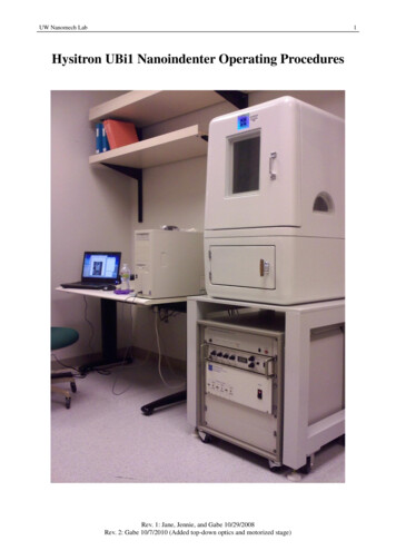
UW Nanomech Lab1Hysitron UBi1 Nanoindenter Operating ProceduresRev. 1: Jane, Jennie, and Gabe 10/29/2008Rev. 2: Gabe 10/7/2010 (Added top-down optics and motorized stage)
UW Nanomech Lab2If at any time you are unsure about something, encounter a problem, orrequire the use of an indenter tip that is not currently mounted, pleasecontact the system administrator for assistance.The current system administrator is GabeEmail: grchow@u.washington.eduPhone: (707) 483 - 0292Table of Contents WORDS OF CAUTION . 3 PREPARING THE HARDWARE AND YOUR SAMPLES . 4 FIRST STEPS . 5 Z-AXIS CALIBRATION . 6 DEFINING SAMPLES . 8 IMAGING . 10 INDENTATION . 12 SETTING UP THE LOAD FUNCTION AND PERFORMING A SINGLE INDENT . 12 PIEZO AUTOMATION. 15 SETTING UP AN AUTOMATED METHOD FOR INDENTATION . 17 INDENT ANALYSIS . 22 SCRATCH TESTING . 24 X-AXIS CALIBRATION . 24 SETTING UP A SCRATCH LOAD FUNCTION AND PERFORMING A SCRATCH. 26 AUTOMATED SCRATCHING . 30 SHUTDOWN PROCEDURES . 31 TROUBLE SHOOTING . 32Rev. 1: Jane, Jennie, and Gabe 10/29/2008Rev. 2: Gabe 10/7/2010 (Added top-down optics and motorized stage)
UW Nanomech Lab3Words of Caution1.2.3.4.Do not leave the lamp on when it is not needed.Always keep an eye on the tip position in the acoustic chamber as you move around withthe x-y-z stage controls. Make sure that the tip will not crash into anything.Tested surfaces have to be smooth enough or the tip can be damaged easily and you willget poor indentation resultsDo not use computer while it is busy performing a function such as an approach or duringany sort of automated testing. Doing so may cause the computer to freeze.Rev. 1: Jane, Jennie, and Gabe 10/29/2008Rev. 2: Gabe 10/7/2010 (Added top-down optics and motorized stage)
UW Nanomech Lab4Preparing the hardware and your samples1.2.3.4.5.6.If the machine is totally off, do not attempt to turn it on. Contact the system administrator.Consult the log book first to see if anyone else is currently using the indenter. If not, writeyour name, the date, and the starting time for your testing into the book.Check your samples to make sure they are clean, smooth, and not tilted. When performinga session with multiple samples, only proceed if they are around the same height (less than1 mm difference). If they are significantly different in height, analyze them one at a time.Open the Acoustic Enclosure and put the sample(s) onto the stage. The sample stage is magnetic. It is recommended that you mount by gluing a magnetto the bottom of your samples. Simply taping samples to the surface can be done, butonly if absolutely necessary. If this is done, the bottom of the sample must be flushwith sample stage (eg. no double stick tape).CAUTION: Do not touch the transducer assembly or the indenter tip while mountingthe samplesLook on the main control unit and check that the knobs have the following settings: Low pass filter: 1000 Hz Displacement Gain: 100 Microscope Feedback: 1000 Display Gain: 100Zero the front panel meter by manually adjusting the coarse knob to less than 0.01.Rev. 1: Jane, Jennie, and Gabe 10/29/2008Rev. 2: Gabe 10/7/2010 (Added top-down optics and motorized stage)
UW Nanomech Lab5First steps1. Start from the windows “Start” menu and open the “TriboScan” Program. The programtakes a few minutes to initialize as it zeroes the stages. Once started, the main windowshould look similar to this:2. To create a workspace, go to the top left of the screen and click the down arrow next to“Default workspace.” Select “New Workspace” and save as any name you desire.3. Turn on the fiber optic light next the UBi1 computer (the V-lux 1000 unit) toilluminate the stage.Rev. 1: Jane, Jennie, and Gabe 10/29/2008Rev. 2: Gabe 10/7/2010 (Added top-down optics and motorized stage)
UW Nanomech Lab6Z-axis Calibration1. Z-axis calibration should be done at the beginning of each session. Go to the“calibration tab” in the main window and click on the “system calibrations” sub tab.Location of microscope feedback software setting and calibrate execution button2. Adjust the microscope gain to 100 in both the software and hardware. This MUST bedone for proper calibration. Software: In the calibration tab, go to the “system calibration” sub tab and look atthe “System Setup – Front Panel Settings.” Change the “Microscope FeedbackGain” to 100. Hardware: Physically adjust the Microscope Feedback Gain to 100 on the maincontrol unit with the knob.3. Now look at where it says “Transducer Calibrations.” Under indentation axis, click“Calibrate”Cal Air Indent buttonRev. 1: Jane, Jennie, and Gabe 10/29/2008Rev. 2: Gabe 10/7/2010 (Added top-down optics and motorized stage)
UW Nanomech Lab74. The software will switch to the Load Function tab where you can click “Cal AirIndent”5. A dialog box will ask “Is the load function set up correctly”, click “Start”6. A dialog box will ask “Re-zero front panel meter on TriboScope controller.” Re-zerothe controller manually on the main control unit.7. A dialog box will ask to set the Displacement Gain to 100 and microscope feedbackgain to 100. Both these should already be set correctly from earlier, but double checkanyways. Click “OK” and the z-axis calibration will run.8. Once the test is finished, it will ask if you want to keep the air calibration data, click“Yes”9. A dialog box will ask to re-zero the controller once again and return the microscopefeedback gain to 1000. Perform both of these tasks on the main control unit, then click“OK”10. A graph will appear with a fitted function of the Electrostatic Force Constant as afunction of displacement. If the fit is reasonable such as the picture below, you canclose the curve fit plot window. If the fit is lousy, double check that the microscopefeedback and displacement gain were set to 100 in both the software and hardwarecontrols during the calibration. Redo the z-axis calibration and if the result is still poor,contact the system administrator for assistance.Example ESF vs Displacement Plot11. Go back to the calibration tab and the system calibrations sub tab. Change themicroscope feedback gain back to 1000 under the front panel settings.CAUTION: It is very important to double check that the microscope feedback gain hasbeen changed back to the value of 1000 in both the software and hardware beforeproceeding. (Steps 9 and 11)Rev. 1: Jane, Jennie, and Gabe 10/29/2008Rev. 2: Gabe 10/7/2010 (Added top-down optics and motorized stage)
UW Nanomech Lab8Defining Samples1. Go to the “Sample Navigation” tab of the software. It will bring you back to the displayseen when the software was first started. Stage controls are in the top right quadrant ofthe screen.Stage controls and X-Y lock toggle2. By default, the x-y stages are locked before any samples are defined. Click the bubblenext to “X-Y Safety DISABLED” so that it turns red to unlock x-y movement.3. The 3-axis movements are done by clicking and holding various parts of the bluereticule graphic. The separated column on the left is for Z-axis control. For example,clicking and holding position “6” will lower the Z-axis at the fastest speed. To lower ata slower speed, click closer to the bolded blue median line. To raise the stage, clickabove the median line.Stage controls guide4. X-Y controls are similarly done by clicking and holding various positions on the X-Ydiagram. For example, holding position 2 will increase the Y position at fastest speed.Holding position “5” will increase X position at slow speed.5. It is now time to define your sample(s). While looking into the acoustic chamber, adjustthe x-y position so that the lighted area is centered over a corner of the sample. Next,lower the z-axis until the corner and a flat portion of the sample area are in opticalfocus. You may need to adjust the x-y position while doing this.Rev. 1: Jane, Jennie, and Gabe 10/29/2008Rev. 2: Gabe 10/7/2010 (Added top-down optics and motorized stage)
UW Nanomech Lab9CAUTION: The bottom stage comes into focus at 32 mm in Z-height, never go abovethis value. Use your sample thickness to estimate when your sample should come intofocus. For example, a 1 mm thick sample will come into focus at 31 mm. The focuspoint is always several millimeters before the point of tip contact. Keep a close eye onthe tip as it descends and make sure that it does not crash into the stage or samplesurface. Do not work with samples that have a large height difference to one anotheras the transducer and tip could easily bump into the thicker sample as it tries to focusonto the thinner one.6. With the corner in focus, click on “New sample” at the sample controls located in thebottom left quadrant of the screen and name the sample. Then click on “Pos. Add” sothat the software saves the location of this corner.New sample and Pos. Add button locations7. Now, navigate to another corner of the sample using the x-y controls. Re-focus theimage at the next corner (if necessary) by adjusting the z-axis slightly. With the nextcorner in focus, click “Pos. Add” once again.8. Repeat step 7 until all corners have been defined.9. You should now see a colored outline of your sample shape next to the navigationwindow where the stage overview is displayed. It will also be seen in the samplescontrol region next to the “Pos. add” and “New Sample” buttons.10. Repeat steps 5-9 until all samples have been defined.11. Once all samples are defined, it is easy to navigate around the samples by right clickingon either the actual live image, the stage overview (above the x-y safety buttons), or thesample window in the bottom left.12. If you will be performing automated tests on all samples during this session withoutimaging the surfaces, navigate to a spot close to the center of each sample (by rightclicking or by using the x-y controls) and perform a quick approach on each. This isnecessary to determine the exact Z-height of each sample before automation. Eachquick approach will take several minutes. Once the quick approaches are done, skipahead to the “Setting up an automated method” section.13. If you will be imaging the surface first before performing tests, a quick approach is notnecessary at this time. It will be performed in the next section.14. Now is a good time to save your workspace. This is done by using the drop down menuin the upper-left. It is the same one that was used earlier to create a workspace, exceptthis time, select “Save Workspace.”Rev. 1: Jane, Jennie, and Gabe 10/29/2008Rev. 2: Gabe 10/7/2010 (Added top-down optics and motorized stage)
UW Nanomech Lab10Imaging1. From the “Sample Navigation” tab of the software, navigate to a spot on the samplewhere imaging is desired by using the x-y controls or by right-clicking.2. Switch to the “Imaging” tab of the software3. Turn off the fiber optic light now since it is not necessary for SPM imaging.4. Look at the imaging controls. Set the appropriate parameters you would like. Thedefault values work well for most samples. They are: Scan Rate: 1 Hz, Tip Velocity: 20 µm/s Scan Size: 10 µm Setpoint: 2 µN Integral Gain: 496 Vertical Scanning: Off (unchecked)Imaging controls settings5. Re-zero the front panel manually by adjusting the coarse knob to a reading 0.0126. Approach the surface by clicking the “approach surface” button on the imaging toolbarin the upper left. It is found directly below the word “Engage.”Image control toolbar - approach button7. Once the sample has been approached, click the green “Go” button on the imagetoolbar to start scanning.8. The four images should now start updating as the scan progresses. The images on theleft side are topographical images in the forwards (top) and backwards (bottom)directions. The images on the right are gradient images in the forwards and backwardsdirections.9. The lower right quadrant displays the image data regarding the current scan lines andRev. 1: Jane, Jennie, and Gabe 10/29/2008Rev. 2: Gabe 10/7/2010 (Added top-down optics and motorized stage)
UW Nanomech Lab11height histograms. Adjusting values in here can make the SPM images look muchbetter by changing the color mapping. The easiest option is to hit the “Auto” button.However sometimes it may need manual adjustment by using the blue sliders.Scanning data display10. If you wish to save a scan image, in the imaging tab, go to the “Image” drop downmenu and click on “Capture File Name.” Select the folder where you want to saveyour image, write the file name, and click “ok”. During the scan, click on the cameraicon on the image toolbar next to the “stop” button. The image will be automaticallysaved to the folder you selected once the scanner has completed the next full pass overthe scanning area. You can analyze the saved images afterwards with the software“ Triboview”Rev. 1: Jane, Jennie, and Gabe 10/29/2008Rev. 2: Gabe 10/7/2010 (Added top-down optics and motorized stage)
UW Nanomech Lab12Indentation Setting up the Load Function and performing a Single Indent1. While imaging the surface, on the image toolbar, there is an option to perform a singleindentation. However, before indenting, there are a few things that need to be setup.2. Make sure that the “Mode” at the top of the screen is set to “Indentation”3. You need to setup the loading parameters for the indentation. Switch to the “LoadFunction” tab in the software and make sure you are on the “Quasi” sub tab.Load Function tab with default loading criteria4. The default load function is an open loop indent with a 10 second load/unload time. Inthis configuration, there is no force feedback therefore this load function is notcommonly used.5. Many former users of the indenter have adopted a 10:5:10 load control function for usewith their characterization. This specifies a load control indent with a 10s loading time,5s hold time at maximum load, and a 10s unloading time. This load function is highlyrecommended for all characterization purposes.6. To change the load function from the default settings, go to the “File” menu and clickon “Open Load Function.” Click and load the “Load Control 10s 5s 10s.ldf” file toload the 10:5:10 function.Rev. 1: Jane, Jennie, and Gabe 10/29/2008Rev. 2: Gabe 10/7/2010 (Added top-down optics and motorized stage)
UW Nanomech Lab13Standard load function with important parameters circled7. After loading the function, the parameters that may require some attention here are: Pre-Load: This should be equal to or greater than the scanning setpoint.Default is 2µN Lift Height: This is the distance the tip is raised over the surface before theindentation begins. This should be equal to or greater than the surfaceroughness. Default is 10 nm and that value works fine for most polishedsamples where roughness is typically very low. Peak force: Set the maximum indentation force.CAUTION: Do not change any of the other parameters unless you have permission to!8. If your work requires the use of a specific load function, a custom load function can becreated by adding segments and manipulating the segment parameters. If this will bedone, please let the system administrator know so that the function can be checked tobe within the limitations of the instrument.9. Once you have the load function set up, switch back to the “Imaging” tab of the software.10. Find a place on the sample that you would like to indent on and center it in the imagearea.11. On the image toolbar, click on the “Test” button to start indentation.Image control toolbar – Test button12. A dialog box will ask if the load function is setup correctly. Click “OK” to proceedwith the indentation. While the indent is running a real time monitor window showyou the progress of the indent. This will be in the form of a red line “traced” with bluedots. The blue dots are real time data coming back, and the red line is the intended loadRev. 1: Jane, Jennie, and Gabe 10/29/2008Rev. 2: Gabe 10/7/2010 (Added top-down optics and motorized stage)
UW Nanomech Lab14function. If the blue dots do not follow the red line, than you need to adjust the loadcontrol feedback gains until they follow the red line as closely as possible. Pleasecontact the system administrator for assistance with this problem.Real-time display during indentationRev. 1: Jane, Jennie, and Gabe 10/29/2008Rev. 2: Gabe 10/7/2010 (Added top-down optics and motorized stage)
UW Nanomech Lab 15Piezo Automation1. To properly characterize the properties of a sample, multiple indents with differentforces are usually necessary. Piezo automation performs an automated set of indentswith varying force on the imaged surface.2. The first step is to find a suitable area for the automated indents. Ideally, the entireimaging area should be smooth and as flat as possible.3. Next, switch to the “Load Function” tab of the software and make sure that the loadfunction is setup properly for the automated indentations that will be performed. Donot worry about the “Peak Force” setting for now as Piezo Automation will changethat accordingly.4. Switch to the “Automation” tab of the software and click on the “Piezo Automation”sub tab. On this screen, there are several important selections to make: Save scan: scan and save the imaging area after the indent array is complete. Thisis suggested. Stay in Contact: Set whether the tip will stay in contact with the surface after thearray is complete. It is highly suggested that you do not do this since you willmost likely be away from the machine during the automation process.Piezo automation settings5. Next, you must choose the number of indents and spacing between the indents in boththe x and y directions. It is suggested that you make the spacing between the indentsseveral times the size of the indent.Rev. 1: Jane, Jennie, and Gabe 10/29/2008Rev. 2: Gabe 10/7/2010 (Added top-down optics and motorized stage)
UW Nanomech Lab16Piezo automation settings6. It is suggested that the time delays Before 1st Indent be set to 180 sec, and BetweenIndents to 120 sec.7. Once everything is setup, click on “Run Piezo Automation” to start the indent array.You will be asked if the load function is set up properly, click “yes
6. With the corner in focus, click on “New sample” at the sample controls located in the bottom left quadrant of the screen and name the sample. Then click on “Pos. Add” so that the software saves the location of this corner. New sample and Pos. Add button locations 7. Now, navigat