Transcription
24Steel Design GuideHollow StructuralSection Connections
24Steel Design GuideHollow StructuralSection ConnectionsJEFFREY PACKER, Ph.D., D.Sc., P.Eng.University of TorontoToronto, OntarioDONALD SHERMAN, Ph.D., P.E.University of Wisconsin–MilwaukeeMilwaukee, WisconsinMAURA LECCE, Ph.D.University of TorontoToronto, OntarioA M ERICA N INST IT U T E O F S T EEL C O N S T RU C T I O N
AISC 2010byAmerican Institute of Steel ConstructionAll rights reserved. This book or any part thereof must not be reproducedin any form without the written permission of the publisher.The AISC logo is a registered trademark of AISC.The information presented in this publication has been prepared in accordance with recognizedengineering principles and is for general information only. While it is believed to be accurate,this information should not be used or relied upon for any specific application without competentprofessional examination and verification of its accuracy, suitability and applicability by alicensed professional engineer, designer or architect. The publication of the material containedherein is not intended as a representation or warranty on the part of the American Institute of SteelConstruction or of any other person named herein, that this information is suitable for any generalor particular use or of freedom from infringement of any patent or patents. Anyone making use ofthis information assumes all liability arising from such use.Caution must be exercised when relying upon other specifications and codes developed by otherbodies and incorporated by reference herein since such material may be modified or amendedfrom time to time subsequent to the printing of this edition. The Institute bears no responsibilityfor such material other than to refer to it and incorporate it by reference at the time of the initialpublication of this edition.Printed in the United States of America
AuthorsJeffrey Packer, Ph.D., D.Sc., P.Eng., is a Bahen/Tanenbaum Professor in Civil Engineering at the Universityof Toronto. He has a bachelor’s degree from the University of Adelaide, Australia (1972), a master’s degreefrom the University of Manchester, U.K. (1975), and doctorates from the University of Nottingham, U.K.(1978, 2006). His research and publications have concentrated on the behavior and design of hollow structuralsection (HSS) connections.Donald Sherman, Ph.D., P.E., is professor emeritus at the University of Wisconsin–Milwaukee. He hasbachelor’s and master’s degrees from Case Institute of Technology (1957, 1960) and a Ph.D. from theUniversity of Illinois (1964). His research and publications include HSS member behavior and simpleconnections to HSS columns.Maura Lecce, Ph.D. is a postdoctoral fellow at the University of Toronto. She has bachelor’s and master’sdegrees from the University of Toronto (2000, 2001) and a Ph.D. from the University of Sydney, Australia(2006). Her research and publications include HSS connections and stainless steel light gage members.PrefaceThis Design Guide is a supplement to the 13th edition of the American Institute of Steel Construction (AISC)Steel Construction Manual and its companion CD. The Manual contains sections on bolting to hollowstructural sections (HSS), welding considerations for HSS, simple shear connections to HSS columns, fullyrestrained moment connections to HSS columns, and design considerations for HSS-to-HSS truss connections.The companion CD has seven examples of simple shear connections to HSS columns. Therefore, this Guidedoes not have a chapter on simple shear connections. The CD also has examples of a transverse plate on arectangular HSS, a longitudinal plate on a round HSS, and HSS braces with end gusset plates, as well asexamples of the design of cap plates, base plates and end plates on HSS members.The examples in this Guide conform to the 2005 AISC Specification for Structural Steel Buildings. Both loadand resistance factor design (LRFD) and allowable strength design (ASD) solutions are presented. Referencesare given to applicable sections of the Specification and to design tables in the Manual. This Guide contains afew additional tables that are applicable to HSS connections. It is recommended that readers of this Guide firstbecome familiar with the Specification provisions for HSS connections and the accompanying SpecificationCommentary.Some of the material in this Guide is based on the AISC Hollow Structural Sections Connections Manualpublished in 1997. However, because the AISC Specification has evolved from that in effect in 1997, the 13thedition Manual and this Guide supersede the previous HSS Manual.Chapter K of the Specification presents the criteria for forces (axial force, in-plane moment and out-of-planemoment) in branch members framing into a main member. In this Guide, these same equations appear in atabular format with drawings showing the connection configuration. This format is easier to follow than thedescriptive text in the Specification. The design examples of direct HSS-to-HSS connections refer to both theappropriate tables in this Guide and the Specification equations.i
ii
Table of ContentsCHAPTER 1 INTRODUCTION . 11.11.21.31.4CHAPTER 6 BRANCH LOADS ON HSS—AN INTRODUCTION . 73HSS AND BOX-SHAPED MEMBERS . 1HSS CONNECTION DESIGN STANDARDSAND SCOPE . 3ADVANTAGES OF HSS . 3OTHER CONSIDERATIONS . 41.4.1 Notch Toughness . 41.4.2 Galvanizing Issues . 41.4.3 Internal Corrosion . 46.16.2CHAPTER 2 WELDING . 52.12.22.32.42.5PRINCIPAL LIMIT STATES . 736.1.1 Chord or Column Wall Plastification . 736.1.2 Chord Shear Yielding (Punching Shear) . 736.1.3 Local Yielding Due to Uneven LoadDistribution . 746.1.4 Chord or Column Sidewall Failure . 75DESIGN TIPS . 76CHAPTER 7 LINE LOADS ANDCONCENTRATED FORCESON HSS. 77TYPES OF HSS WELDS . 52.1.1 Fillet Welds . 52.1.2 PJP and CJP Groove Welds. 62.1.3 Flare-Bevel and Flare-V Groove Welds . 6WELD INSPECTION. 7EFFECTIVE SIZE OF FILLET WELDS . 8EFFECTIVE WELD LENGTH . 8WELDED JOINT DESIGN EXAMPLES . 107.17.27.37.47.5SCOPE AND BASIS . 77LIMIT STATES. 77CONNECTION NOMINAL STRENGTHTABLES . 79LONGITUDINAL-PLATE AND CAP-PLATECONNECTIONS . 83CONNECTION DESIGN EXAMPLES . 84CHAPTER 3 MECHANICAL FASTENERS . 153.13.23.3CHAPTER 8 HSS-TO-HSS TRUSSCONNECTIONS . 91FASTENERS IN SHEAR . 15FASTENERS IN TENSION . 15BOLTED JOINT DESIGN EXAMPLES . 168.18.28.38.4CHAPTER 4 MOMENT CONNECTIONS . 294.14.24.34.44.5W-BEAMS TO HSS COLUMNS . 29CONTINUOUS BEAM OVER HSS COLUMN. 29THROUGH-PLATE CONNECTIONS. 30DIRECTLY WELDED CONNECTIONS . 30CONNECTION DESIGN EXAMPLES . 318.58.6CHAPTER 9 HSS-TO-HSS MOMENTCONNECTIONS . 123CHAPTER 5 TENSION AND COMPRESSIONCONNECTIONS . 495.15.25.35.45.55.65.7SCOPE AND BASIS . 91NOTATION AND LIMIT STATES . 91CONNECTION CLASSIFICATION. 92TRUSS MODELING AND MEMBERDESIGN . 93CONNECTION NOMINAL STRENGTHTABLES . 96CONNECTION DESIGN EXAMPLES . 1009.19.29.3TYPES OF END CONNECTIONS . 49END TEE CONNECTIONS . 50SLOTTED HSS/GUSSET CONNECTION . 51END PLATE ON ROUND HSS . 51END PLATE ON RECTANGULAR HSSWITH BOLTS ON TWO SIDES . 52END PLATE ON RECTANGULAR HSSWITH BOLTS ON FOUR SIDES . 53CONNECTION DESIGN EXAMPLES . 559.4SCOPE AND BASIS . 123NOTATION AND LIMIT STATES . 123CONNECTION NOMINALCAPACITY TABLES . 125CONNECTION DESIGN EXAMPLES . 128SYMBOLS . 141REFERENCES. 144iii
iv
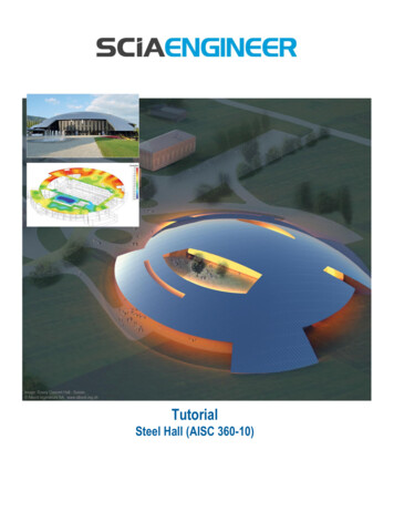
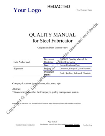
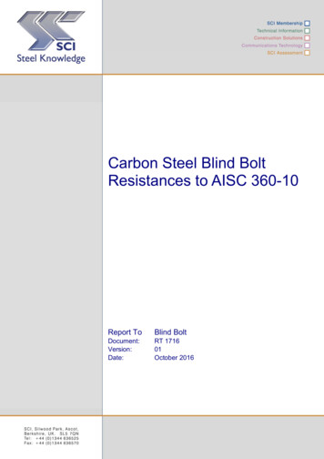
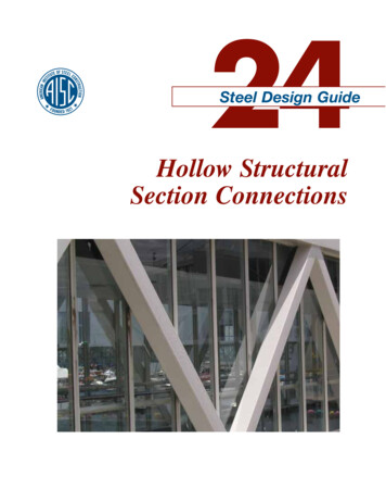
Chapter 1IntroductionIn recent years, the popularity of hollow structural sections(HSS) has increased dramatically. The pleasing aestheticappearance generated by architecturally exposed hollowsections is much favored by architects, and HSS also canprovide reduced weight and surface area when compared toequivalent open sections. Some stunning examples of exposed HSS in building interiors are shown in Figure 1-1.Connections usually have been the challenging aspectfor the designer of structures that involve HSS. This AISCDesign Guide demonstrates design methods for a widerange of connection types. Note that, in many cases, thelocal strength of the HSS at the connection is an integralpart—and perhaps a limitation—of the design. Moreover,note that reinforcing the connections of HSS assembliesoften is not an available option, for either architectural orfabrication reasons.1.1HSS AND BOX-SHAPED MEMBERSHSS manufactured according to American Society for Testing and Materials (ASTM) standard A500 (ASTM, 2007a)are cold-formed in tube mills, and have an electric resistancewelded (ERW) continuous seam weld. This “weld” is produced without the addition of any additional consumable.The weld bead on the outside is always removed, but theweld bead that results on the inside of the HSS is generallyleft in place. However, this inside weld bead can be removedat the point of manufacture if this requirement is specifiedto the tube mill; this may be desirable if one HSS is insertedinto another, for example with telescoping poles.(a) Opryland Hotel, Nashville, Tennessee.Round, square and rectangular HSS produced in accordance with the ASTM A500 Grade B standard are readilyavailable throughout North America. Rectangular HSS arealso frequently termed “shaped” sections. ASTM A500Grade C is increasingly available, and many HSS productsare now dual-certified as meeting the requirements in bothASTM A500 Grade B and Grade C. The relative materialstrengths of these ASTM A500 HSS are shown in Table 1-1.Note that a particular grade has different yield strengths forround versus rectangular shapes.In some parts of the United States, various pipe productsare readily available and used in lieu of round HSS. ASTMA53 (ASTM, 2007c) Grade B pipe, which is included in theAmerican Institute of Steel Construction (AISC) Specification for Structural Steel Buildings, hereafter referred to as theAISC Specification (AISC, 2005a), has a lower yield strengththan its ASTM A500 counterpart (see Table 1-1). All loadtables in the 13th edition AISC Steel Construction Manual,hereafter referred to as the AISC Manual (AISC, 2005b), forHSS are based on ASTM A500 Grade B strengths, and theload tables for pipe use ASTM A53 Grade B strengths.Other North American HSS products that have propertiesand characteristics similar to the approved ASTM productsare produced in Canada (CSA, 2004). This standard allowsfor two types of finished product: Class C (cold-formed) andClass H (cold-formed and stress relieved by heat treatment).Class H HSS have reduced levels of residual stress, which enhances their performance as compression members and mayprovide better ductility in the corners of rectangular HSS.(b) Interior of Rock and Roll Hall of Fame, Cleveland, Ohio.Fig. 1-1. Contemporary examples of HSS in construction.AISC DESIGN GUIDE 24 / HOLLOW STRUCTURAL SECTION CONNECTIONS / 1
Table 1-1. North American Manufacturing Standards for HSSwith Mechanical Properties of Common 500RectangularGradeFy , ksi (MPa)Fu , ksi (MPa)B42 (290)58 (400)C46 (315)62 (425)B46 (315)58 (400)C50 (345)62 (425)PipeASTM A53B35 (240)60 (415)Hot-formedHSSASTM A501B50 (345)70 (483)Cold-formedand 350W51 (350)65 (450)It should also be noted that very large diameter tubular sections are available to American Petroleum Institute (API)specifications; many different grades are available, and specified outside diameters range from 0.405 in. to 84 in. (API,2007).The designation used to identify square and rectangular HSSis, for example:HSS8t4t)In this designation, the whole numbers are the height andwidth, and the fraction is the nominal thickness. Decimalnumbers are used for the outside diameter and nominalthickness in the designation of round HSS, for example:HSS6.000t0.375The designation for pipe is a traditional form for threegrades, including:Standard; Std.Extra Strong; x-strongDouble Extra Strong; xx-strongThe diameter designated for pipe is a nominal value between the specified inside and outside diameters, forexample:Pipe 8 x-strongThe dimensions and geometric properties of HSS and pipeare included in Part 1 of the AISC Manual in the followingtables:Table 1-11: Rectangular HSSTable 1-12: Square HSSTable 1-13: Round HSSTable 1-14: PipeDimensional tolerances of the products are also included inthe following tables:Table 1-27: Rectangular and Square HSSTable 1-28: Round HSS and PipeThe ASTM cold-formed material standard tolerances permit the wall thickness to be 10% under the nominal wallthickness. Consequently, the mills consistently produce HSSwith wall thicknesses less than the nominal wall thickness.Section B3.12 in the AISC Specification accounts for thisby designating a design wall thickness of 0.93 times thenominal thickness. The design wall thickness is included inthe tables of dimensions and properties in the AISC Manual,and all properties (A, D/t, I, Z, S, etc.) are based on the designwall thickness.Round, square and rectangular HSS manufactured according to the ASTM A500 standard are available in perimetersup to 64 in. and in thicknesses up to h in. Larger sizes insquare and rectangular sections are classified as box-shapedmembers in the AISC Specification. A standard product lineof these box sections up to 128-in. perimeter is produced byplacing two flat strips in a brake press to form two identicalhalves of a finished tube size. A backing bar is tack weldedto each leg of one of the half sections. Then, the two half sections are fitted together toe-to-toe and submerged arc weldedtogether to complete the square or rectangular section. Thesesections are produced with the full nominal thickness so thatthe design wall thickness of 0.93t does not apply.The standard sizes of HSS and larger box-shaped members produced appear in HSS availability listings on theAISC website (www.aisc.org) and periodically in AISC’sModern Steel Construction magazine. Tables of dimensionsand section properties for larger box-shaped members can beobtained from the manufacturer.2 / HOLLOW STRUCTURAL SECTION CONNECTIONS / AISC DESIGN GUIDE 24
The ASTM A501 standard (ASTM, 2007b) for hot-formedtubing is included in the AISC Specification even thoughthese products have not been produced in North America forseveral decades. However, ASTM A501 has recently beenrevised to add Grade B, which is a hot-finished product withthe mechanical properties shown in Table 1-1. The manufacturing process is similar to cold-formed HSS, but the finalshaping and sizing are completed after the steel has beenheated to a full normalizing temperature. These productsare made by European manufacturers in round, square, rectangular and elliptical shapes (Packer, 2008). Such sectionsare essentially produced to the European standard EN10210Parts 1 and 2 (CEN, 2006a, 2006b), and the elliptical hollowsections have a major-to-minor axis dimension ratio on theorder of 2:1.Sections up to 16-in. square and 0.625-in. thick are produced with ERW seams and are available in several sizes.There is also a product line of jumbo HSS in sizes up to32-in. square and thicknesses up to 2.36 in. For thicknessesup to 1 in., the sections are manufactured with ERW seams.For greater thicknesses, submerged arc welding (SAW) isused for the seams. SAW box sections can be produced fromplate material (such as ASTM A572 Grade 50 as used in Example 3.3), but they generally are of a size that exceeds the64-in. periphery limitation in ASTM A500. As such, thesecross sections do not necessarily meet the requirements inASTM A500. The specifier should contact the producer(s)of such cross sections to determine the cross sections thatare made, as well as their cross-sectional properties and applicable production requirements. This information is alsoavailable in the EN10210 standard (CEN, 2006a, 2006b).1.2HSS CONNECTION DESIGN STANDARDSAND SCOPEThe 2005 AISC Specification supersedes all previous AISCSpecifications, including the 1999 Load and ResistanceDesign Specification for Structural Steel Buildings (AISC,1999), the 1989 Specification for Structural Steel Buildings– Allowable Stress Design and Plastic Design (AISC, 1989)including Supplement No. 1, and the 2000 Load and Resistance Factor Design Specification for Steel Hollow StructuralSections (AISC, 2000). Direct HSS-to-HSS welded connecUJPOT BSF OPX DPWFSFE JO IBQUFS , PG UIF "*4 Specification. 'SBNJOH DPOOFDUJPOT VTF UIF DSJUFSJB JO IBQUFS , for concentrated loads and applicable portions of Chapter Jfor welding, bolting and connecting elements. Some aspectsof HSS connection design, such as prying action, do not appear directly in the AISC Specification, but use guidelinesfrom the AISC Manual or published research.The scope of the AISC Specification, and hence this Design Guide, for HSS connections is limited to:r 4UBUJD EFTJHOr 4JOHMF QMBOBS EFTJHOr 4ZNNFUSZ QFSQFOEJDVMBS UP UIF QMBOF OP PGGTFU FMFNFOUTr 6OàMMFE BOE VOSFJOGPSDFE )44Guidelines for conditions outside the scope of the AISCSpecification appear in other codes and design guides:r 'BUJHVF "84 ;IBP FU BM r 4FJTNJD EFTJHO ,VSPCBOF FU BM r .VMUJQMBOBS DPOOFDUJPOT "84 1BDLFS BOE Henderson, 1997)r 0GGTFU DPOOFDUJPOT "84 r POOFDUJPOT UP DPODSFUF àMMFE )44 ,VSPCBOF FU BM 2004)1.3ADVANTAGES OF HSSHSS are very efficient sections for torsion and compressionloading. For compressive loading, this is due to the favorableweak-axis radius of gyration, which often controls the available compressive strength.It is not possible to make direct cost comparisons withother shapes because prices vary with time, application andgeographic location. However, Table 1-2 compares two ofthe key factors that influence cost: weight and surface areathat may require some type of preparation. The comparisonsare between ASTM A992 wide-flange shapes, ASTM A500Grade B round HSS, and ASTM A500 Grade B square HSS.Sections are selected for a particular length and load usingAISC Manual Tables 4-1, 4-4 and 4-5. The load and resistance factor design (LRFD) load is 1.5 times the allowablestrength design (ASD) load, and because this is the calibration load ratio in the AISC Specification, the same sectionsare determined in LRFD and ASD. The selected sections havecomparable depths and available strengths. Data is providedfor two cases: a compression member with moderate length(KL 16 ft) and load, and a longer compression member(KL 32 ft) with a higher load.The wide-flange section is used as the basis for comparison and is assigned 100% for weight and surface area. It isapparent from Table 1-2 that these example HSS are 10 to20% lighter than the corresponding wide-flange members,and have one-third to one-half less surface area. The latter isparticularly influential for decreasing painting costs. Moreover, one should also bear in mind that this section comparison is performed using ASTM A500 Grade B material,which is readily available. If ASTM A500 Grade C material (with higher yield strength) were used, the advantage iseven greater.AISC DESIGN GUIDE 24 / HOLLOW STRUCTURAL SECTION CONNECTIONS / 3
Table 1-2. Comparison of W-Shape and HSS Compression MembersKL 16 ftPu 200 kips (LRFD)Pa 133 kips (ASD)Length andrequiredstrengthKL 32 ftPu 600 kips (LRFD)Pa 400 kips (ASD)HSSASTM A500 Grade BHSSASTM A500 Grade 14t109HSS14.000t0.625212 (LRFD)141 (ASD)208 (LRFD)138 (ASD)229 (LRFD)152 (ASD)664 (LRFD)442 (ASD)620 (LRFD)412 (ASD)734 (LRFD)488 (ASD)Weight, lb/ft(see 9.6(82%)Surface area,ft2/ft(see %)4.53(65%)Member typeand ngth, kipsSquareHSS14t14tNote: The number in parentheses represents the percent of weight or surface area relative to the wide-flange option.1.4OTHER CONSIDERATIONS1.4.1 Notch ToughnessASTM A500 (ASTM, 2007a) has no notch toughnessrequirements. However, ASTM A500 importantly notes“ Products manufactured to this specification may not besuitable for those applications such as dynamically loadedelements in welded structures, etc., where low-temperaturenotch-toughness properties may be important.” The newASTM A501 Grade B includes a Charpy V-notch impact testwith the minimum energy absorbed of 20 ft-lb (27 J) at atemperature of 0 F ( 18 C) (ASTM, 2007b).1.4.2 Galvanizing IssuesIn the ASTM A500 standard the outside corner radius ofsquare and rectangular HSS is required to be equal to or lessthan 3t, where t is the wall thickness (ASTM, 2007a). Thestandard, ASTM A143/A143M-03 (ASTM, 2003) states that“a cold bending radius of three times the section thickness will ordinarily ensure satisfactory properties in the finalproduct.” Thus, all square and rectangular HSS produced inNorth America are potentially prone to corner cracking during hot-dip galvanizing because the outside corner radius averages 2t, and the upper limit on outside corner radius for allASTM A500 HSS is at the minimum bending radius recomNFOEFE GPS HBMWBOJ[JOH ,JOTUMFS T SFQPSU QPJOUFE PVU that “ the amount of cold work, as measured by the bendingradius, is the most important single factor to consider whenthere is concern for brittle-type failure of steel galvanizedafter cold working.” ASTM A143/A143M-03 continues toadvise that “ For heavy cold deformation exemplified bycold rolling subcritical annealing at temperatures from1200 to 1300 F [650 to 705 C] should be used.”For hot-dip galvanizing, holes to allow for filling, ventingand drainage are necessary, and adequate sizing minimizesdifferential thermal stresses experienced by the structureupon galvanizing. Vent holes with a minimum diameter of' in. (13 mm) and drain holes with a diameter of 1 in.(25 mm) are recommended.1.4.3 Internal CorrosionThe AISC Specification Commentary Section B3.11 discusses the topic of internal corrosion in HSS. In summary:1. Corrosion will not occur in an enclosed building and is aconsideration only in HSS exposed to weather.2. Internal corrosion will not occur in a sealed HSS.3. Pressure-equalizing holes at locations where water cannot flow into the HSS by gravity will prevent capillaryaction or aspiration through fine openings, such as anunwelded length of two plates or members in contact.4. Internal protection is required only in open HSS wherea change in air volume by ventilation or direct flow ofwater is possible, or when the HSS is subject to a temperature gradient that would cause condensation.Care should be taken to keep water from remaining in the HSSduring or after construction, because the expansion causedby freezing can create pressure sufficient to burst the HSS.4 / HOLLOW STRUCTURAL SECTION CONNECTIONS / AISC DESIGN GUIDE 24
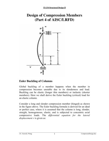
Chapter 2WeldingAISC Design Guide 21, Welded Connections—A Primer forEngineers (Miller, 2006) provides excellent general advicefor engineers on welding, including some particular remarkson welding HSS. With HSS-to-HSS welded connections,there are two design philosophies that can be used for welddesign:1. The weld can be proportioned so that it develops the yieldstrength of the connected branch wall at all locationsaround the branch. This will represent an upper limiton the weld size—and a conservative design procedure.This approach is particularly appropriate if plastic stressredistribution is required in the connection. The sameeffective weld size should be maintained all around theattached branch, except for the “hidden weld” in HSSUP )44 QBSUJBMMZ PWFSMBQQFE , PS / DPOOFDUJPOT TFF Chapter 8).not be used for design of the welds. This is because the weldsare not “loaded in plane” for these truss-type connections.To facilitate fillet welding in square or rectangular HSSto-HSS connections, the branch should sit on the “flat” of themain through (chord) member, as shown in Figure 2-1, for a“stepped” configuration rather than a “matched” configuration (branch and chord of equal width).In some situations, the attached element in the joint maybe skewed, or not perpendicular, to the continuous elementas shown in Figure 2-2.2. The weld can be proportioned so that it resists the applied forces in the branch. This approach is particularlyappropriate if the branch forces are low relative to thebranch member strength, such as when branches aresized for aesthetic reasons (e.g., the branches of a simplysupported truss may be the same throughout the truss,yet, at the center of the truss, the web member forces willbe very low under uniformly distributed load). If this design philosophy is adopted, effective weld lengths mustbe taken into account (see Section 2.4), and the sameeffective weld size should still be maintained all aroundthe attached branch, with the entire branch perimeterwelded (including the “hidden toe,” if applicable).2.1Fig. 2-1. Stepped HSS-to-HSS connections.TYPES OF HSS WELDSThe four common types of welds used in HSS connections,in order of preference, are:1.2.3.4.Fillet weldsPartial-joint-penetration (PJP) groove weldsFlare-bevel and flare-V-groove weldsComplete-joint-penetration (CJP) groove welds Localdihedralangle-toe zonewtp or tb Localdihedralangle-heel zonew2.1.1 Fillet WeldsFillet welds are the most economical welds, and should beused in HSS connections whenever practical. However, for5 : , BOE DSPTT DPOOFDUJPOT EFàOFE JO 4FDUJPO XJUI fillet welds, it is recommended that the fillet weld strengthenhancement, as given by AISC Specification Equation J2-5,wwFig. 2-2. Skewed joint.AISC DESIGN GUIDE 24 / HOLLOW STRUCTURAL SECTION CONNECTIONS / 5
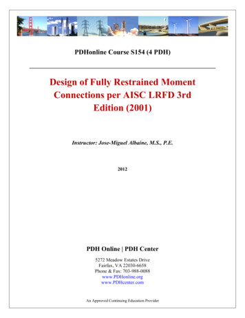
Table 2-1. Weld Size Factors for SkewDihedral Angle ( 0.8161300.780concealed inside the HSS. In such cases, CJP groove weldsare also made with a backup weld at the root placed from theoutside. Careful preparation of the joint is required to ensurethe proper gap at the root. Because of the limited access andthe skill required to fill the open root, often while out of position, a special 6GR certification is required for the welder(AWS, 2008).Round HSS-to-HSS joints are complex and the bevelpreparation varies around the perimeter of the joining member. A good discussion of various types of backing and jointdetails is given by Post (1990).2.1.3 Flare-Bevel and Flare-V Groove WeldsAs the dihedral angle decreases from 90 , the theoreticalthroat increases. On the other side with the larger angle, thetheoretical throat decreases. Table 2-1 provides the equivalent weld size factors to account for the skew angle. Theactual weld size, w, is multiplied by the factor to obtain theequivalent weld size, weq, with the same throat and a 90 dihedral angle. On the side with the larger angle, the filletweld size must be adjusted for the root opening, which cannot exceed m in. according to AWS D1.1/D1.1M (AWS,2008) Section 5.22.1, if the attached element is cut square asshown in Figure 2-2. Example 2.1 shows the calculation ofa skewed fillet weld.Flare-bevel and flare-V groove welds are used at therounded corners of rectangular and square HSS. They areused to attach flat elements that are wider than the HSS, orfor matched HSS connections where the width of a branchmember is the same as that of the continuous member in theconnection. Flare-V groove welds are used when the cornersof two square or rectangular HSS are welded together, suchas in back-to-back, double-chord trusses. Figure 2-3 showsexamples of flare-bevel and flare-V groove welds.Table J2.2 of the AISC Specification gives the effectiveweld sizes for flare groove welds depending on the weldingprocess, and presuming that the welds are filled flush withthe outside face of the HSS. These are based on experimentalresearch by Packer and Frater (2005), and take into accounttypical gap sizes that occur at the weld root. The effectiveweld sizes for flare-bevel groove welds are:hR for2.1.2 PJP and CJP Groove WeldsIn HSS-to-HSS connections, the welding can be done onlyfrom one side. Therefore, any groove-welded joint detailthat requires preparation and welding on both sides—orbackgouging—is not possible.PJP groove welds are preferable to CJP groove welds,when it is possible to use them. Prequ
AISC Specification (AISC, 2005a), has a lower yield strength than its ASTM A500 counterpart (see Table 1-1). All load tables in the 13th edition AISC Steel Construction Manual, hereafter referred to as the AISC Manual (AISC, 2005b), for HSS are based on ASTM A500 Grade B strengths, and