Transcription
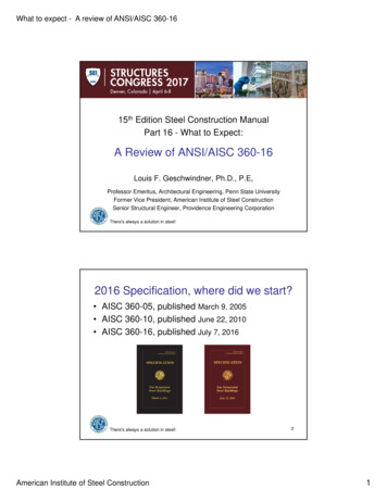
What to expect - A review of ANSI/AISC 360-1615th Edition Steel Construction ManualPart 16 - What to Expect:A Review of ANSI/AISC 360-16Louis F. Geschwindner, Ph.D., P.E,Professor Emeritus, Architectural Engineering, Penn State UniversityFormer Vice President, American Institute of Steel ConstructionSenior Structural Engineer, Providence Engineering CorporationThere’s always a solution in steel!2016 Specification, where did we start? AISC 360-05, published March 9, 2005 AISC 360-10, published June 22, 2010 AISC 360-16, published July 7, 2016There’s always a solution in steel!American Institute of Steel Construction21
What to expect - A review of ANSI/AISC 360-162016 Specification, what can youexpect? AISC’s continued commitment to a singlespecification for all types of elements. Continued availability of provisions forLRFD and ASD (a unified specification)Ru φRn and Ra Rn Ω Some expansion but overall, minimalchange.There’s always a solution in steel!3What was the goal for 2016? To again produce a specification that reflectsminimal change from previous editions. Implement only essential changes. Continue to coordinate with all AISC standards Integrate with non AISC standards such asASCE 7, IBC, and ACI. Reference appropriate other newly approvedstandards.There’s always a solution in steel!American Institute of Steel Construction42
What to expect - A review of ANSI/AISC 360-162016 AISC Specification Basic organization has not changed– Still 14 Chapters, A through N– Still 8 Appendices, 1 through 8 Within some chapters, provisions havebeen reorganized Throughout there have been editorialchanges that will not be discussed hereThere’s always a solution in steel!5Chapter A General Provisions A3. Material– Tubing and pipe are now combined underSection A3.1a(b) Hollow Structural Sections(HSS) ASTM A1065, 50 ksi welded HSS added ASTM A1085, new HSS standard with tightertolerances added– ASTM A1066, HSLA plate produced bythermo-mechanical controlled process added Grades 50 to 80There’s always a solution in steel!American Institute of Steel Construction63
What to expect - A review of ANSI/AISC 360-16Chapter A General Provisions A3.3 Bolts, washers and nuts– ASTM F3125 added. It includes the formerA325 and A490 type standards as grades.– Thus, ASTM A325, A490, F1852, and F2280no longer exist as separate standards.– ASTM F3111 and F3040, 200 ksi hex headand twist-off bolts are added as Group C.These are proprietary productsThere’s always a solution in steel!7Chapter B DesignRequirements B3. Design Basis– This section has been completely reorganized– It provides the charging language for theremainder of the Specification in this neworder:1. Design by LRFD2. Design by ASD3. Required Strength4. Design of Connections and Supports5. Design of Diaphragms and CollectorsThere’s always a solution in steel!American Institute of Steel Construction84
What to expect - A review of ANSI/AISC 360-16Chapter B DesignRequirements B3. Design Basis6. Design of Anchorages to Concrete7. Design for Stability8. Design for Serviceability9. Design for Structural Integrity – new provisions10. Design for Ponding – revised provisions11. Design for Fatigue12. Design for Fire Conditions13. Design for Corrosion EffectsThere’s always a solution in steel!9Chapter B DesignRequirements B3.9 Design for Structural Integrity– When required by applicable building code(a) Column splice tensile strength(b) Beam end connection tension strength(c) Bracing connection tensile strengthStrength requirements for structural integrity evaluatedindependently of other strength requirements.There’s always a solution in steel!American Institute of Steel Construction105
What to expect - A review of ANSI/AISC 360-16Chapter B DesignRequirements B3.10 Design for Ponding– Requirement regarding minimum roof slope toavoid ponding analysis is removed.– Now requires that stability for ponding bechecked unless roof surface is configured toprevent the accumulation of water.– Appendix 2 is referenced and there theassumptions for use of the two approachesare defined.There’s always a solution in steel!11Chapter B DesignRequirements B4.2 Design Wall Thickness for HSS– Two new material specifications, ASTMA1065 and A1085. Both permit use of nominal thickness as designwall thickness A1085 – an HSS standard with tighter tolerancesthan A500 etc. A1065 – 50 ksi plate material produced to astandard with typical plate tolerances.There’s always a solution in steel!American Institute of Steel Construction126
What to expect - A review of ANSI/AISC 360-16Chapter B DesignRequirements B4.2 Design Wall Thickness for HSSUser Note: A pipe can be designed using theprovisions of the Specification for round HSSsections as long as the pipe conforms to ASTMA53 Class B and the appropriate limitations ofthe Specification are used.There’s always a solution in steel!13Chapter C Design for Stability C2.2 Consideration of Initial SystemImperfections– System Imperfections Imperfections in location of points of intersection ofmembers (column out-of-plumbness)– Member Imperfections User note now makes it clear that these arealready taken into account in the column equationsfrom Chapter E. (column out-of-straightness)There’s always a solution in steel!American Institute of Steel Construction147
What to expect - A review of ANSI/AISC 360-16Chapter C Design for Stability C2.3(b) Adjustments to Stiffness– Flexural stiffness reduction factor, τb, nowdefined for composite members (in Chapter I)– Also redefined for members with slenderelementsτ b 4 (α Pr Pns ) 1 (α Pr Pns ) (C2-2b) For nonslender element sections Pns Fy Ag For slender element sections Pns Fy AeThere’s always a solution in steel!15Chapter C Design for Stability K-factor– First introduced in the 1963 Specification– Set equal to 1.0 when using the direct analysismethod of Chapter C (since 2005)– For 2016, KL, the effective length, has been replacedwith Lc . This makes the designation of effectivelength simpler since in some instances, such as fortorsion, the traditional definition of K is not helpful.– This has been implemented throughout the 2016SpecificationThere’s always a solution in steel!American Institute of Steel Construction168
What to expect - A review of ANSI/AISC 360-16Chapter D Tension The only change in this chapter has to dowith shear lag for longitudinally weldedconnections to tension members. Case 2 no longer applies to weldedconnections unless they use transversewelds in combination with longitudinalwelds.17There’s always a solution in steel!Chapter D Tension Thus, Case 4 has been expanded toinclude shapes as well as plates and theshear lag factor equation revised.Case 4: Plates, angles, channels with welds at heels,tees, and W-shapes with connected elements, wherethe tension load is transmitted by longitudinal weldsonlyl1U 3l 2 x 1 3l 2 w2 l Tl There’s always a solution in steel!American Institute of Steel ConstructionPlate orConnected Elementwl1 l22Tl2189
What to expect - A review of ANSI/AISC 360-16Example 1 Determine the shear lag factor for aWT7x24 welded to a plate with longitudinalwelds at the flange tips.U w 8.03 in.x 1.35 in.l3l 2 x 1 3l 2 w2 l Ae UAnU2010U2016l 2w 16.10.9160.923(0.916) 0.845l 1.5w 12.00.8880.871(0.888) 0.773l w 8.030.8320.750(0.832) 0.624There’s always a solution in steel!19Chapter E Compression E4. Torsional and Flexural-Torsional Buckling ofSingle Angles and Members without SlenderElements– Consider what to do when twisting is not about theshear center.– Deleted the special case for double angles and tees.– Clarified that this section applies to single angles withb t 0.71 E Fy(This had been b/t 20 in 2010)There’s always a solution in steel!American Institute of Steel Construction2010
What to expect - A review of ANSI/AISC 360-16Chapter E Compression E5. Single Angle Compression Members– Clarified that flexural-torsional buckling need not beconsidered for b t 0.71 E Fy E6. Built-up members– Clarified need for Class A or B faying surfaces insome situations. E7. Members with Slender Elements– Completely revised the approach and made it similarto AISI approach.21There’s always a solution in steel!Chapter E Compression E7. Members with Slender Elements– Stiffened and unstiffened elements treatedsimilarly (same effective width equation)– The critical stress is the same, regardless ofelement slenderness (E3-2, E3-3)– Slender element comes into play througheffective areaPn Fcr AeThere’s always a solution in steel!American Institute of Steel Construction(E7-1)2211
What to expect - A review of ANSI/AISC 360-16Chapter E Compression E7. Members with Slender Elements– whenλ λrFyFcrbe b(E7-2)23There’s always a solution in steel!Chapter E Compression E7. Members with Slender Elements– whenλ λrFyFcr Fel Felbe b 1 c1 FFcrcr (E7-3)2There’s always a solution in steel!American Institute of Steel Construction λ Fel c2 r Fy λ (E7-4)2412
What to expect - A review of ANSI/AISC 360-16Chapter E Compressionc 1 1 4c12Table E7-12c1Effective Width Imperfection Adjustment Factor, c1and c2 Factor.CaseSlender Elementc1c2(a)Stiffened elements except walls of square and rectangular HSS0.181.31(b)Walls of square and rectangular HSS0.201.38(c)All other elements0.221.49λr c3kc EFyThere are 6 distinct values for c3, found in Table B4.1akc 1 except for flanges of built-up I-shaped sectionsRound HSS still treated differently25There’s always a solution in steel!Chapter E Compression E7. Members with Slender Elements F Fbe b 1 c1 el el Fcr Fcr (E7-3)which, for webs of I-shaped members, ends upbeingbe 1.95tEFcrThere’s always a solution in steel!American Institute of Steel Construction 0.351 E 1 btF()cr 2613
What to expect - A review of ANSI/AISC 360-16Chapter E Compression E7. Members with Slender Elementsbe 1.95tEFcrwhich for 2010 wasbe 1.92t 0.351 E 1 btF()cr SAMEEf 0.34 E 1 btf() 27There’s always a solution in steel!Chapter E Compression E7. Members with Slender Elements2010AQ eAgQFy Fcr 0.658 Fe Pn Fcr AgAe Ag (b be )t QFy There’s always a solution in steel!American Institute of Steel Construction2016Fy Fcr 0.658 Fe Pn Fcr Ae Fy Ae QAg2814
What to expect - A review of ANSI/AISC 360-16Example 2 Determine the compressive strength of aslender flange I-shape. Lc KL 20 ftFor 2010Flange: 24 x 0.5 in.Web: 24 x 0.75 in.b 24 1.17 kc E Fy 23.7t0.90 EkcQs 0.6412Fy ( b t )ry 5.24 in.kc 4 0.707h twλ rf 0.64 kc E Fy 13.0 b f 2t f 24Thus, the flange is slenderLc 20 (12 ) 45.85.24r2πE 136 ksiFe 2( Lc r )Pn 29.0 ( 42.0 ) 1220 kipsQFy 0.641( 50 ) 0.236 2.25Fe136()Fcr 0.641 0.658( 0.236) ( 50 ) 29.0 ksi29There’s always a solution in steel!Example 2 For 2016, start with FcrLc 20 (12 ) 45.8r5.24π2 E 136 ksiFe 2( Lc r )λ rf 13.0b f 2t f λ rf Fy Fcr 13.0 50 42.9 14.0Thus, the flange is slenderFy 50 0.368 2.25Fe 136Fcr 0.658( 0.368) ( 50 ) 42.9 ksi be b 1 c1 12 1 0.22 Fel Fcr32.6 32.6 8.45 42.9 42.9FelFcrAe 24 ( 0.75 ) 24 ( 0.5 ) 2 ( 8.45 )( 0.5 ) 38.5 in.2Pn 42.9 ( 38.5 ) 1650 kipsThere’s always a solution in steel!American Institute of Steel ConstructionQ Ae 38.5 0.917Ag 42.03015
What to expect - A review of ANSI/AISC 360-16Chapter E CompressionBuilt-up I-shape with Slender Flange,Fy 50 ksi2500b t f 24.0 0.64 kc E Fy 12.962000Flanges 24 in. x 0.5 in.Web 24 in. x 0.75 in.1800 k1650 kPn, kips15002010 Pn2016 Pn1000w/o slender elements1220 kFor 2010,Q 0 .64150000204060Effective Length, Lc, (KL)80100For 2016, worst caseAe/Ag 0.904There’s always a solution in steel!31Chapter F Flexure F1. General Provisions– Clarify Cb for cantilevers F4. and F5. Noncompact and slender webs– Revised effective radius of gyration for LTB F7. HSS and Box Sections– Clarified here and throughout that box sections weredoubly symmetric and treated like rectangular HSS– For box sections added slender web and lateraltorsional bucklingThere’s always a solution in steel!American Institute of Steel Construction3216
What to expect - A review of ANSI/AISC 360-16Chapter F Flexure F9. Tees and Double Angles– Revised LTB provisions– Revised stem local buckling– Cleaned-up and reorganized section F10. Single Angles– Reduced conservatism for LTB by making amore realistic assumption for b/t F13.1 Holes in tension flanges– Clarified use of minimum section modulus33There’s always a solution in steel!Chapter F Flexure F9. Tees and Double Angles – LTB20102016Stems in tensionL p Lb LrLp and Lr not usedM n M cr π EI y GJLb d IB 2.3 y Lb J(B 1 B2 L Lp Mn M p (M p M y ) b Lr Lp Lb LrSameequationsStem in tension, BStem in compression, -BThere’s always a solution in steel!American Institute of Steel Construction)In this range, 2016 more conservativeM n M cr 1.95 EI y J B 1 B2 LbStems and web legs in compressionTees and double angles treated a bitdifferently3417
What to expect - A review of ANSI/AISC 360-16Chapter F Flexure F9. Tees and Double Angles – Stem LB20100.842016EdE 1.03Fy twFy0.84 dFcr 2.55 1.84tw Fy FyE dE 1.03twFyFcr dFcr 1.43 0.515tw Fy FyE dE 1.52twFy0.69 E d tw EdE 1.52Fy twFyFcr 21.52 E d tw 2Double angles treated like 2 single angles35There’s always a solution in steel!Example 3 Determine the nominal moment strengthfor the limit state of stem local buckling fora WT12x34 d tw 28.7, S x 15.6 in.32010 Limits2016 Limitsλ p 0.84 E Fy 20.2λ p 0.84 E Fy 20.2λ r 1.03 E Fy 24.8λ r 1.52 E Fy 36.6d tw 28.7 λ rλ p d tw 28.7 λ rFcr 0.69 E 24.3 ksi( d tw )M n Fcr S x 24.3 (15.6 ) 379 in.-kips2There’s always a solution in steel!American Institute of Steel Construction d Fy Fcr 1.43 0.515 Fy 40
AISC 360-10, published June 22, 2010 AISC 360-16, published July 7, 2016. What to expect - A review of ANSI/AISC 360-16 American Institute of Steel Construction 2 There’s always a solution in steel! 3 2016 Specification, what can you expect? AISC’s continued commitment to a single specification for all types of elements. Continued availability of provisions for LRFD and ASD .File Size: 366KBPage Count: 35
