Transcription
PDHonline Course S154 (4 PDH)Design of Fully Restrained MomentConnections per AISC LRFD 3rdEdition (2001)Instructor: Jose-Miguel Albaine, M.S., P.E.2012PDH Online PDH Center5272 Meadow Estates DriveFairfax, VA 22030-6658Phone & Fax: 703-988-0088www.PDHonline.orgwww.PDHcenter.comAn Approved Continuing Education Provider
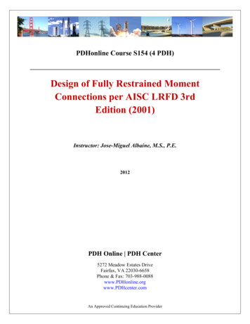
www.PDHcenter.comPDH Course S154www.PDHonline.orgDesign of Fully Restrained Moment ConnectionsAISC LRFD 3rd Edition (2001)COURSE CONTENT1. TYPES OF CONSTRUCTIONIn steel framework, beam end connections occur quite often that theyinfluence costs very strongly and have attracted a great deal of attentionfrom design engineers and researches. This effort has resulted in a greatvariety of forms that can be executed safely. The study of beam endconnections entails the considerations of a range of assumptions made inframe analysis regarding these connections. The new AISC specificationprovides for three basic types of framing, which relate to the endconnections of beams to columns.Section A2.2 of the LRFD specification defines the following types ofconstruction:Type FR (fully restrained), which is commonly referred as “rigid frame”(continuous frame), considers that connections have enough stiffness tomaintain the angles between the connected members. In other words, a fulltransfer of moment and little or no relative rotation of members within thejoint. This type of connection was formerly referred to as Type 1construction in previous editions of the AISC.Type PR (partially restrained) assumes that the connections have insufficientstiffness to maintain the angles between the intersecting members. This typeof connections requires that the strength, stiffness and ductilitycharacteristics of the connections be considered in the analysis and design.This course will not cover this type of connection, formerly referred to asType 3 construction in previous editions of the AISC. Part 11 of the LRFDdeals with an alternative and a more simplified approach, namely the“flexible moment connection”.Simple framing is the other type of construction, where the connectionrestraint is ignored (unrestrained, free-ended), and the connection isdesigned to resist gravity loads only while allowing relative rotation of theconnected members (no moment transfer is taken into account). This type ofPage 1 of 28
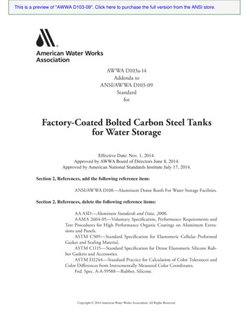
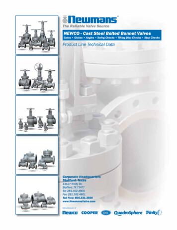
www.PDHcenter.comPDH Course S154www.PDHonline.orgconnection was formerly referred to as Type 2 construction in previouseditions of the AISC.The general behavior of these three types of connection is illustrated belowin Figure No.1; typical examples of these connection types are shown onFigures 2, 3, and 4.Figure No.1Page 2 of 28
www.PDHcenter.comPDH Course S154www.PDHonline.orgFigure 2Figure 4Figure 3Page 3 of 28
www.PDHcenter.comPDH Course S154www.PDHonline.org1. AISC LRFD 3rd Edition – November 2001Load and resistance factor design (LRFD) is based on a consideration offailure conditions rather than working load conditions. Members and itsconnections are selected by using the criterion that the structure will fail atloads substantially higher than the working loads. Failure means eithercollapse or extremely large deformations.Load factors are applied to the service loads, and members with theirconnections are designed with enough strength to resist the factored loads.Furthermore, the theoretical strength of the element is reduced by theapplication of a resistance factor.The equation format for the LRFD method is stated as:ΣγiQi φ Rn(Eq. 1)Where:Qi a load (force or moment)γi a load factor (LRFD section A4 Part 16, Specification)Rn the nominal resistance, or strength, of the component underconsiderationφ resistance factor (for bolts and welds given in LRFD Chapter J, Part 16)The LRFD manual also provides extensive information and design tables forthe design considerations of bolts in Part 7, Part 9, 10 and Part 16 Chapter J,section J3. Design considerations for welds are addressed in Part 8, and Part16, Chapter J, section J2.Other parts of the manual cover connections such as flexible momentconnections (Part11), bracing and truss connections (Part 13), columnsplices (Part 14), hanger connections, bracket plates, and crane-railconnections (Part 15). Our discussion will be limited to the design of fullyrestrained (FR) moment connections presented in Part 12 and Part 16,Chapter J.Page 4 of 28
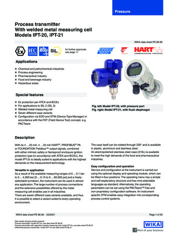
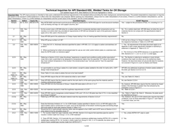
www.PDHcenter.comPDH Course S154www.PDHonline.org3. Basic Behavior of FR Moment ConnectionsFully restrained (FR) moment connections must have sufficient rigidity tomaintain the angles between the intersecting angles as shown on Fig. No. 5.Since it is quite difficult if not impossible to achieve full rigidity in a FRmoment connection, the small amount of flexibility present is usuallyneglected and the connections are idealized as preventing relative rotation.Figure 5LRFD specification Section B9 states that end connections in FRconstruction must be designed to carry the factored forces and moments,allowing for some inelastic but self-limiting deformation of a part of theconnection.In a FR connection the moment can be resolved into an effective tensioncompression couple acting as axial forces at the beam flanges, as shown onFig. No. 6, while the shear force is considered to be resisted entirely throughthe web shear connection. The eccentricity in the shear connection can beneglected entirely since the angle between the members in a FR momentconnection remains unchanged under loading. Axial forces are normallyassumed to be distributed uniformly across the beam flanges, and are addedto the couple forces from the applied moment.Page 5 of 28
www.PDHcenter.comPDH Course S154www.PDHonline.orgFigure 6Furthermore, moment connections transmit concentrated forces to columnflanges, and these forces must be accounted in the design to prevent localflange bending (from the tension force), local web yielding, web crippling,and web compression buckling caused by the compression force. Horizontalstiffeners may be required to address these local effects in accordance withLRFD Specification (Part 16), Chapter K, sections K1.2, K1.3, K1.4, andK1.6 respectively.There are a great variety of arrangements for FR moment connections andwe will concentrate on three major designs: a) the flange Tee-Stub bolted FRmoment connection, b) the flanged-plated FR moment connection, and c) thedirectly welded flanged FR moment connections. Both bolted and weldedconsiderations will be covered for these connections.4. Bolting Considerations for FR Moment ConnectionsPage 6 of 28
www.PDHcenter.comPDH Course S154www.PDHonline.orgThe LRFD allows bolts in bearing in either standard holes or slotted holesperpendicular to the line of force. The applicable limit states for the boltsare covered under Part 7 of the LRFD.Moment resistance of bolted FR moment connections depends on tensionand shear in the fasteners. One of the most common bolted FR momentconnections is the Flange Tee-Stub connection shown on Fig. No.7.Figure 7The design of this connection involves the transfer of the tensile force Tthrough bolts (in the stem of tee) in single shear, and direct tension throughbolts in the flange of the tee. The bolts in tension require consideration of“prying action”.Prying forces arises when a relatively thin plate deflects outward, thuspressing the unsupported edges against the supporting piece, see Fig. 8.Page 7 of 28
www.PDHcenter.comPDH Course S154www.PDHonline.orgFigure 8LRFD section J3.6 states that for bolts “the applied load shall be the sum ofthe factored loads and any tension resulting from prying action produced bydeformation of the connected parts”. Procedure to compute prying forces iscovered in Part 9 of the LRFD.For FR moment bolted connections the most commonly used high strengthbolts come in two grades: ASTM A325 and ASTM 490. These bolts can beused in several joint types, such as snug-tightened (bearing joints),pretensioned joints, and slip-critical joints. Each joint type is to be specifiedin accordance with the required performance in the structural connection.Although the unfinished bolt designated as ASTM A307 is not precluded tobe used in FR moment connections (except for the limitations specified inLRFD J1.11), these bolts are primarily used in light structures, secondary orbracing members, platforms, catwalks, purlins, girts, light trusses, and otherstructures with small loads and static in nature. The A307 bolts are usedpredominantly in connections for wood structures.Page 8 of 28
www.PDHcenter.comPDH Course S154www.PDHonline.orgExample 1Design a bolted T-Stub moment connection for the beam shown on Figure 9,supporting both gravity and wind loads.Figure 9Design Parameters:Steel Specification ASTM A992 - Bolts ASTM A325Loads:Dead Moment, MD 20 ft-kipsLive Moment, ML 38 ft-kipsWind Moment, Mw 82 ft-kipsShear to be resisted by web connection (not in the scope of this course)Page 9 of 28
www.PDHcenter.comPDH Course S154www.PDHonline.orgStep1: Determine the factored design moment:1.4 D M 28 ft-k1.2D 1.6L M 84.8 ft-k1.2D 1.6W 0.5 L M 174.2 ft-k !----- Governs(Note, other combinations may be considered in an actual design, refer toASCE 7-02)For a W18 x 50, d 18 in.Step 2 : Find the maximum Tension force on the flangeT C M / d 174.2 x 12 / 18 116.1 kipsStep 3: Bolt requirementsTry 7/8” diameter bolts – Single shear at the beam flanges and tension at thecolumn facea) Tee to beam flanges:From AISC LRFD Table 7-10, the design shear strength of a 7/8” φ A325bolt with the threads included in the shear plane (snugged-tight joint)φFV 21.6 kips[from φFnAb (Table J3.2, where φ 0.75, Fn 48 ksi, and Ab 0.601 in2)]No. of bolts required 116.1 / 21.6 5.4 USE 6 bolts to connect the Tstubs to the beam flangesb) Tee to column:From AISC LRFD Table 7-14, the design tensile strength of a 7/8” φ A325bolt is given as:φFt 40.6 kips[from φFnAb (Table J3.2, where φ 0.75, Fn 90 ksi, and Ab 0.601 in2)]No. of bolts required 116.1 / 40.6 2.9 USE 4 bolts to connect the Tstubs to the column flangePage 10 of 28
www.PDHcenter.comPDH Course S154www.PDHonline.orgCheck Prying effect, Figure 10 (from LRFD Part 9):T-Stub Properties: tf 1.09 in tw 0.62 in bf 7.87 in g 4 inThe thickness required to eliminate prying action tmin is determined by:Figure 10Page 11 of 28
www.PDHcenter.comPDH Course S154www.PDHonline.orgWhere:rut 116.1 / 4 29 kipsp tributary length of flange per pair of boltsp (5.5 2 x 1.5) / 2 4.25” g then p 4 in (see Figure No. 9)b 4/2 – 0.62/2 1.69 inb’ 1.69 – 0.875/2 1.25 inFy 36 ksi (T-stub)Then, tmin. 1.06 in. tf 1.09 in. Therefore prying effect is eliminatedUSE 4 – 7/8” φ A325 bolts to connect the T-stub to the columnStep 4: Check T-stub Capacitya) Check the capacity of the web in tensionFrom LRFD Specification part D:Yielding of the gross section; φtPn 0.90 x Fy x AgFy Specified minimum yield strength of the T, 36 ksiAg gross area of the memberφtPn 116.1 kips, then the minimum width required iswmin 116.1 / (0.9 x 36 x 0.62) 5.78 inFor rupture in the net section:φtPn 0.75 x Fu x AeFu Specified minimum tensile strength of T-stub, 58 ksiAe Effective net area of memberMinimum Ae required 116.1 / (0.75 x 58) 2.67 in2The minimum effective width be 2.67 / 0.62 4.3 inPage 12 of 28
www.PDHcenter.comPDH Course S154www.PDHonline.orgThe provided width of the T-stub is at a minimum 7 ½ in. (the flange widthof the W18 x 50), and taken as 8 inches at the column face,bemin 7.5 – 2(1) 5.5 in 4.3 inThe capacity of the T-stub web is considered adequate in resisting the tensileforces.b) The capacity of the T-stub flange at the column faceThe flange thickness is larger than the required tmin for prying forces, sothe flange of the T-section is thick enough to resist any local bendingthus reducing any prying action to insignificant level.Step 5: Other Considerations for the Design of a FR Moment Connectiona) For the configuration and final connection evaluation the followingsitems will require further investigation that are beyond the scope ofthis course such as: geometric layouts of structural bolts such as, sizeand use of bolt holes, minimum and maximum bolt spacing, minimumand maximum edge distance, bearing strength of bolts, and the designrupture strength of the connected parts.These limit states has been addressed in PDH course S-134,Design of Bolts in Shear-Bearing Connections per AISC LRFD 3rd Edition (2001)b) Comments on the fabrication of FR moment connectioni)ii)iii)iv)The beam end must be cut back far enough to keep the flangethickness from interfering with the bolt head.The nuts should be placed on the inside of the column flangeThe beam web connection (to resist the vertical shear force) mustclear the edge of the T-stub flangeShims should be furnished in thicknesses of 1/16-in. to 1/8-in. toallow for beam and fabrication tolerances.Finally, the main advantage of the T-stub bolted connection is theprovision of a bolted connection that eliminates all complications thatmay arise in field welded connections. The extended end-plate FRmoment connection is another field bolted connection that avoid fieldwelding. This connection is covered in depth by the AISC in DesignGuide number 13.Page 13 of 28
www.PDHcenter.comPDH Course S154www.PDHonline.org5. Column Limit StatesColumns in FR moment connections must be checked for the following limitstates conditions (see Figure 11):Flange local bending (LRFD Specification Part 16, Section K1.2)Web local yielding (LRFD Specification Part 16, Section K1.3)Web crippling (LRFD Specification Part 16, Section K1.4)Web compression buckling (LRFD Specification Part 16, Section K1.6)Web panel-zone shear (LRFD Specification Part 16, Section K1.7)Figure 11Page 14 of 28
www.PDHcenter.comPDH Course S154www.PDHonline.org5.a) Flange Local Bending, LRFD Chapter K, section K1.2Applicable to both ten
The LRFD manual also provides extensive information and design tables for the design considerations of bolts in Part 7, Part 9, 10 and Part 16 Chapter J, section J3. Design considerations for welds are addressed in Part 8, and Part 16, Chapter J, section J2. Other parts of the manual cover connections such as flexible moment connections (Part11), bracing and truss connections (Part 13), column .