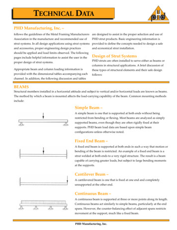
Transcription
53:134 Structural Design IIDesign of Beams (Flexural Members)(Part 5 of AISC/LRFD)References1. Part 5 of the AISC LRFD Manual2. Chapter F and Appendix F of the AISC LRFD Specifications(Part 16 of LRFD Manual)3. Chapter F and Appendix F of the Commentary of the AISCLRFD Specifications (Part 16 of LRFD Manual)Basic TheoryIf the axial load effects are negligible, it is a beam; otherwise it is abeam-column.J.S Arora/Q. Wang1BeamDesign.doc
53:134 Structural Design IIShapes that are built up from plate elements are usually called plategirders; the difference is the height-thickness ratio h 5.70 tw h 5.70 t wEFybeamEFyplate girderhof the web.twBendingM bending moment at the cross section under considerationy perpendicular distance from the neutral plane to the point ofinterestI x moment of inertia with respect to the neutral axisS x elastic section modulus of the cross sectionFor elastic analysis, from the elementary mechanics of materials, thebending stress at any point can be foundfb MyIxThe maximum stressf max McMM IxI x / c SxThis is valid as long as the loads are small and the material remainslinearly elastic. For steel, this means f max must not exceed Fy andthe bending moment must not exceedM y Fy S xJ.S Arora/Q. Wang2BeamDesign.doc
53:134 Structural Design IIM y the maximum moment that brings the beam to the point ofyieldingFor plastic analysis, the bending stress everywhere in the section isFy , the plastic moment is A M p Fy a Fy Z 2 M p plastic momentA total cross-sectional areaa distance between the resultant tension and compression forceson the cross-section A Z a plastic section modulus of the cross section 2 ShearShear stresses are usually not a controlling factor in the design ofbeams, except for the following cases: 1) The beam is very short. 2)There are holes in the web of the beam. 3) The beam is subjected to avery heavy concentrated load near one of the supports. 4) The beam iscoped.f v shear stress at the point of interestV vertical shear force at the section under considerationQ first moment, about the neutral axis, of the area of the crosssection between the point of interest and the top or bottom ofthe cross sectionJ.S Arora/Q. Wang3BeamDesign.doc
53:134 Structural Design III moment of inertia with respect to the neutral axisb width of the cross section at the point of interestFrom the elementary mechanics of materials, the shear stress at anypoint can be foundfv VQIbThis equation is accurate for small b . Clearly the web will completelyyield long before the flange begins to yield. Therefore, yield of theweb represents one of the shear limit states. Take the shear yieldstress as 60% of the tensile yield stress, for the web at failurefv Vn 0.60FyAwAw area of the webThe nominal strength corresponding to the limit state isVn 0.60Fy AwThis will be the nominal strength in shear provided that there is noshear buckling of the web. This depends onh, the width-thicknesstwratio of the web. Three cases:No web instability:hE 2.45twFyVn 0.60 Fy AwJ.S Arora/Q. WangAISC Eq. (F2-1)4BeamDesign.doc
53:134 Structural Design IIInelastic web buckling: 2.45 2.45 E / FyVn 0.60 Fy Aw h / tw Elastic web buckling: 3.07EhE 3.07Fy t wFy AISC Eq. (F2-2)Eh 260Fy t w 4.52 E Vn Aw 2 (h / t w ) AISC Eq. (F2-3)Failure ModesShear: A beam can fail due to violation of its shear design strength.Flexure: Several possible failure modes must be considered. A beamcan fail by reaching M p (fully plastic), or it can fail by Lateral torsional buckling (LTB), elastically or inelastically Flange local buckling (FLB), elastically or inelasticallyJ.S Arora/Q. Wang5BeamDesign.doc
53:134 Structural Design II Web local buckling (WLB), elastically or inelasticallyIf the maximum bending stress is less than the proportional limit whenbuckling occurs, the failure is elastic. Otherwise, it is inelastic.Lateral Torsional BucklingThe compressive flange of a beam behaves like an axially loadedcolumn. Thus, in beams covering long spans the compression flangemay tend to buckle. However, this tendency is resisted by the tensileflange to certain extent. The overall effect is a phenomenon known aslateral torsional buckling, in which the beam tends to twist anddisplace laterally. Lateral torsional buckling may be prevented by: 1)Using lateral supports at intermediate points. 2) Using torsionallystrong sections (e.g., box sections). 3) Using I-sections with relativelywide flanges.Local BucklingThe hot-rolled steel sections are thin-walled sections consisting ofa number of thin plates. When normal stresses due to bending and/ordirect axial forces are large, each plate (for example, flange or webplate) may buckle locally in a plane perpendicular to its plane. Inorder to prevent this undesirable phenomenon, the width-to-thicknessratios of the thin flange and the web plates are limited by the code.AISC classifies cross-sectional shapes as compact, noncompactand slender ones, depending on the value of the width-thicknessratios. (LRFD-Specification Table B5.1)λ width-thickness ratioJ.S Arora/Q. Wang6BeamDesign.doc
53:134 Structural Design IIλ p upper limit for compact categoryλr upper limit for noncompact categoryThen the three cases areλ λpand the flange is continuously connected to theweb, the shape is compact.λ p λ λrthe shape is noncompactλ λrthe shape is slenderThe above conditions are based on the worst width-thickness ratio ofthe elements of the cross section. The following table summarizes thewidth-thickness limits for rolled I-, H- and C- sections (for Csections, λ b f / t f . The web criterion is met by all standard I- andC- sections listed in the Manual. Built-up welded I- shapes (such asplate girders can have noncompact or slender elements).ElementλFlangebf2t fWebJ.S Arora/Q. Wanghtwλpλr0.38EFy3.76EFy70.83EFy 105.70EFyBeamDesign.doc
53:134 Structural Design IIDesign Requirements1. Design for flexure (LRFD SPEC F1)Lbunbraced length, distance between points braced against lateraldisplacement of the compression flange (in.)Lplimiting laterally unbraced length for full plastic bendingcapacity (in.) – a property of the sectionLrlimiting laterally unbraced length for inelastic lateral-torsionalbuckling (in.) – a property of the sectionEmodulus of elasticity for steel (29,000 ksi)Gshear modulus for steel (11,200 ksi)Jtorsional constant (in.4)Cwwarping constant (in.6)Mrlimiting buckling moment (kip-in.)M p plastic moment,M p Fy Z 1.5M yM y moment corresponding to the onset of yielding at the extremefiber from an elastic stress distribution M y Fy S xM u controlling combination of factored load momentM n nominal moment strengthφbresistance factor for beams (0.9)The limit of 1.5My for Mp is to prevent excessive working-loaddeformation that is satisfied whenJ.S Arora/Q. Wang8BeamDesign.doc
53:134 Structural Design IIM p Fy Z 1.5M y or Fy Z 1.5Fy S orZ 1.5SDesign equationApplied factored moment moment capacity of the sectionORRequired moment strength design strength of the sectionM u φb M nIn order to calculate the nominal moment strength Mn, first calculateL p , Lr , and M r for I-shaped members including hybrid sections andchannels asE- a section propertyFyL p 1.76ryLr ry X1FL1 1 X 2 FL2 - a section propertyM r FL S x - section propertyAISC Eq. (F1-4)AISC Eq. (F1-6)AISC Eq. (F1-7)FL Fy Fr for nonhybrid member, otherwise it is the smallerof Fyf Fr or Fyw (subscripts f and w mean flange andweb)Fr compressive residual stress in flange, 10 ksi for rolled shapes;16.5 ksi for welded built-up shapesJ.S Arora/Q. Wang9BeamDesign.doc
53:134 Structural Design IIX1 πSxEGJA24C S X2 w x I y GJ AISC Eq. (F1-8)2AISC Eq. (F1-9)Sxsection modulus about the major axis (in.3)Iymoment of inertia about the minor y-axis (in.4)ryradius of gyration about the minor y-axis (in.4)Nominal Bending Strength of Compact Shapes()If the shape is compact λ λ p , no need to check FLB (flange localbuckling) and WLB (web local buckling). Lateral torsional buckling (LTB)If Lb L p , no LTB:M n M p 1.5M yAISC Eq. (F1-1)If L p Lb Lr , inelastic LTB: Lb L p MM n Cb M p M p M r p L L p rNote that Mn is a linear function of Lb.()AISC Eq. (F1-2)If Lb Lr (slender member), elastic LTB:M n M cr M pJ.S Arora/Q. WangAISC Eq. (F1-12)10BeamDesign.doc
53:134 Structural Design IIM cr Cb πLb2 πE EI y GJ I y Cw M p L b Cb S x X 1 2Lb / ry1 X 12 X 2(2 Lb / ryAISC Eq. (F1-13))2Note that Mcr is a nonlinear function of LbCb is a factor that takes into account the nonuniform bending momentdistribution over an unbraced length LbM A absolute value of moment at quarter point of the unbracedsegmentM B absolute value of moment at mid-point of the unbraced segmentM C absolute value of moment at three-quarter point of the unbracedsegmentM max absolute value of maximum moment in the unbraced segment12.5M maxAISC Eq. (F1-3)2.5M max 3M A 4M B 3M CIf the bending moment is uniform, all moment values are the sameCb giving Cb 1 . This is also true for a conservative design.J.S Arora/Q. Wang11BeamDesign.doc
53:134 Structural Design IINominal Bending Strength of Noncompact Shapes()If the shape is noncompact λ p λ λ r because of the flange, the webor both, the nominal moment strength will be the smallest of thefollowing: Lateral torsional buckling (LTB)If Lb L p , no LTB:M n M p 1.5M yAISC Eq. (F1-1)If L p Lb Lr , inelastic LTB: M n Cb M p M p M r (J.S Arora/Q. Wang12 Lb L p Mp L L p r)AISC Eq. (F1-2)BeamDesign.doc
53:134 Structural Design IINote that Mn is a linear function of LbIf Lb Lr , elastic LTB:M n M cr M pM cr CbAISC Eq. (F1-12)2πLb πE EI y GJ I y C w M p L b AISC Eq. (F1-13)Note that Mcr is a nonlinear function of Lb Flange local buckling (FLB)If λ λ p , no FLB.If λ p λ λr , the flange is noncompact: λ λp MpMn M p M p Mr λr λ p ()AISC Eq. (A-F1-3)Note that Mn is a linear function of λ Web local buckling (WLB)If λ λ p , no WLB.If λ p λ λr , the web is noncompact: λ λp MpMn M p M p Mr λr λ p ()AISC Eq. (A-F1-3)Note that Mn is a linear function of λSlender sections λ λr : For laterally stable slender sectionsM n M cr SFcr M pM cr critical (buckling) momentFcrcritical stressJ.S Arora/Q. Wang13BeamDesign.doc
53:134 Structural Design II2. Design for shear (LRFD SPEC F2)φvresistance factor for shear (0.9)Vucontrolling combination of factored shearVnnominal shear strengthFyw yield stress of the web (ksi)Awweb area, the overall depth d times the web thickness twDesign equation forh 260 :twVu φvVnThe design shear strength of unstiffened web is φvVn , where 0.60Fyw Aw 2.45 E / Fyw Vn 0.60Fyw Aw h / tw 4.52E Aw 2 ()ht/ w hE 2.45twFyw2.453.07EhE 3.07Fyw t wFywEh 260Fyw t wThese are Eqs. (F2-1), (F2-2) and (F2-3) in Chapter F of LRFDSpecifications. Forh 260 , web stiffeners are required, and thetwprovision of Appendix F2 must be consulted. Note that shear is rarelyJ.S Arora/Q. Wang14BeamDesign.doc
53:134 Structural Design IIa problem in rolled steel beams; the usually practice is to design abeam for flexural and check for shear.3. Design for serviceabilityDeflection of beam should be checked with service loads. This is theserviceability requirement of a structure. (LRFD-Specification L).Design Procedure Compute the factored load moment M u (required momentstrength); it should be less than or equal to the design strength,φb M n . The weight of the beam is part of the dead load but isunknown at this point. A value may be assumed, or ignoredtemporarily. Select a shape that satisfies the flexural strength requirement.This can be done in one of the following two ways:Assume a shape, compute the design strength and compare itwith the factored load moment. Revise if necessary.Use the beam design charts in LRFD Part 5. Check the shear strength. Check the deflection (serviceability requirement).J.S Arora/Q. Wang15BeamDesign.doc
Part 5 of the AISC LRFD Manual 2. Chapter F and Appendix F of the AISC LRFD Specifications (Part 16 of LRFD Manual) 3. Chapter F and Appendix F of the Commentary of the AISC LRFD Specifications (Part 16 of LRFD Manual) Basic Theory If the axial load effects are negligible, it is a beam; otherwise it is a beam-column. J.S Arora/Q. Wang 1 BeamDesign.doc . 53:134 Structural Design II Shapes that .