Transcription
Carbon Steel Blind BoltResistances to AISC 360-10Report ToBlind BoltDocument:Version:Date:RT 171601October 2016
Blind bolts to AISC 36-10VersionIssue01Oct2016PurposeIssue to clientAuthorDGBReviewer ApprovedAXWAlthough all care has been taken to ensure that all the information containedherein is accurate, The Steel Construction Institute assumes no responsibility forany errors or misinterpretations or any loss or damage arising therefrom.For information on publications, telephone direct:or Email: publications@steel-sci.comFor information on courses, telephone direct:or Email: education@steel-sci.comEmail: Reception@steel-sci.comWorld Wide Web site: http://www.steel-sci.comii 44 (0) 1344 636505 44 (0) 1344 636500
Blind bolts to AISC 36-10EXECUTIVE SUMMARYThis report covers the recalculation of the resistance of carbon steel blind boltsin a form suited to the American market and design completed in accordance withthe AISC specification 360-101.Resistances in tension, shear, bearing and combined shear and tension arepresented, for both Allowable Stress Design (ASD) and Load and ResistanceFactor Design (LRFD).The recalculation is based on the test program reported in SCI Report RT 1303of July 20092.A suggested presentation of the resistances is provided in Appendix A.iii
Blind bolts to AISC 36-10iv
Blind bolts to AISC 36-10ContentsPage NoEXECUTIVE SUMMARYiii1INTRODUCTION1.1 Blind Bolts772TENSION RESISTANCE2.1 AISC specification2.2 Characteristic tensile resistance2.3 Design tension resistances999103SHEAR RESISTANCE3.1 AISC Specification3.2 Characteristic shear resistance over the slot3.3 Design shear resistance over the slot3.4 Characteristic shear resistance over the threads3.5 Design shear resistance over the threads1212121314144COMBINED SHEAR AND TENSION165BEARING RESISTANCE5.1 AISC specification5.2 Eurocode design5.3 Recommendations for bearing strength (LRFD)5.4 Recommendations for bearing strength (ASD)1818181920REFERENCES21Appendix APresentation of results22v
Blind bolts to AISC 36-10vi
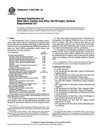
Blind bolts to AISC 36-1011.1INTRODUCTIONBlind BoltsA blind bolt is illustrated in Figure 1.1. The bolts are used in a horizontalorientation.The bolt shank has a machined slot, within which a rotating ‘toggle’ is positionedand retained by a pin, about which the toggle can rotate in one direction. Thetoggle cannot rotate in the opposing direction due to the shape of the toggle andthe stepped slot machined in the bolt shank.After inserting the bolt through the supporting material, the bolt is turned 180 ,which allows the toggle to turn through 90 under the action of gravity forming aperpendicular stop inside the supporting structure. A mark on the end of the boltindicates the orientation of the bolt, and a special tool can be insertedlongitudinally through machined slots on the outside of the bolt shank to confirmthat the toggle has rotated.The nut can then be tightened in the normal way. The bolts are not intended tobe used as pre-loaded assemblies.It should be emphasised that due to the special shape of the toggle and machinedslot, tension force in the bolt is transferred by bearing between the toggle and thebolt shank. The pivot pin plays no part in transferring load.Figure 1.1Blind boltCarbon steel blind bolts are supplied in Class 10.9 material with a minimumultimate tensile strength of 1000 N/mm2.Carbon steel blind bolts are available in the following diameters:M8, M10, M12, M16, M20, M24 which correspond to diameters (in inches) of0.315, 0.394, 0.472, 0.630, 0.787 and 0.945.7
Blind bolts to AISC 36-10In 2009, an extensive series of tests were undertaken to establish designresistances. The test work, statistical analysis and derivation of designresistances is reported in SCI report RT13032.8
Blind bolts to AISC 36-102TENSION RESISTANCE2.1AISC specificationTension resistance is covered by clause J3-6, where the resistance of a bolt intension, Rn is given by:Rn FnAbwhere:FnAbis the nominal tensile stress Fnt from Table J3.2.is the nominal unthreaded body area.From the commentary to the AISC specification1 (clause J3-6), the nominaltensile strength value, Fnt is given by:Fnt 0.75Fuwhere:Fuis the ultimate strength of the bolt.The 0.75 factor allows for the approximate ratio of the effective area of thethreaded portion of the bolt to the area of the unthreaded shank.Because the tensile resistance of the blind bolt is based on the actual crosssectional area of the assembly, the 0.75 factor is not applied.According to clause J3-6:(LRFD) The design resistance is Rn and 0.75.(ASD) The design resistance is Rn/ and 2.00.2.2Characteristic tensile resistanceThe characteristic tensile resistance of a blind bolt is therefore given by:Rn 0.537 FuAt (see expression 19 of RT 1303).where:FuAtis the ultimate strength of the bolt (1000 N/mm2).is the minimum cross sectional area, at the pin.The characteristic tension resistance is given in Table 2.1 (From Table 7.2 inRT 1303).9
Blind bolts to AISC 36-10Table 2.12.3Characteristic tension resistanceBoltCross section at thepin (mm2)Rn Tension 693.450.16M20134.672.29M24191.6102.89Design tension resistancesDesign tension resistances are given in Table 2.2.Table 2.2Design tension resistancesBolt Diameter(mm)10(inch)ASDLRFDRn/ 6200.78736.18.1254.212.19240.94551.411.5777.217.35
Blind bolts to AISC 36-1011
Blind bolts to AISC 36-103SHEAR RESISTANCE3.1AISC SpecificationShear resistance is covered by clause J3-6, where the resistance of a bolt inshear, Rn is given by:Rn FnAbwhere:FnAbis the nominal shear stress Fnv from Table J3.2.is the nominal unthreaded body area.From the commentary to the AISC specification (clause J3-6), the nominal shearstrength value, Fnv is given by:Fnv 0.563Fuwhere:Fuis the ultimate strength of the bolt.The 0.563 factor applies if the shear plane is in the unthreaded shank. A furtherreduction of 0.8 is applied if the shear plane passes through the threaded portionof the shank (because the calculation still uses the unthreaded area).Because the shear resistance of the blind bolt is based on the actual crosssectional area of the assembly, the 0.563 factor is applied.According to clause J3-6:(LRFD) The design resistance is Rn and 0.75.(ASD) The design resistance is Rn/ and 2.00.3.2Characteristic shear resistance over the slotThe characteristic shear resistance of a blind bolt with the shear plane in theslotted length is therefore given by:Rn 0.563 FuAslot (compare with expression 26 of RT 1303).where:FuAslot12is the ultimate strength of the bolt (1000 N/mm2).is the cross sectional area, at the slot.
Blind bolts to AISC 36-10The characteristic shear resistance over the slot is given in Table 3.1.Table 3.13.3Characteristic shear resistance over the slotBoltRn Shear 4123.6Design shear resistance over the slotDesign shear resistances over the slot are given in Table 3.2.Table 3.2Design shear resistance over slotBolt Diameter(mm)(inch)ASDLRFDRn/ 8413
Blind bolts to AISC 36-103.4Characteristic shear resistance over the threadsThe characteristic shear resistance over the threads is given in Table 3.3.Table 3.33.5Characteristic shear resistance over the threadsBoltRn Shear 24198.5Design shear resistance over the threadsDesign shear resistances over the threads are given in Table 3.4.Table 3.4Design shear resistance over threadsBolt Diameter(mm)14(inch)ASDLRFDRn/ .833.46
Blind bolts to AISC 36-103.5.1 Checks against published dataTo verify the resistances quoted in Table 3.4, it is noted that the resistances forM20 and M24 should be approximately the same as for ¾” and 1” bolts.The resistances in Table 3.5 are taken from the AISC Manual.Table 3.5Design resistances from AISC ManualBolt diameterShear Strength (kips)ASDLRFD¾”15.022.51”26.740.0The difference can be explained by the variation in diameter and the ultimatestrength of the bolt (1040 N/mm2 in the AISC Manual, compared to 1000 N/mm2for the blind bolt).For M20 bolt (LRFD):19.052 1040 23.4 22.1 (compares with 22.5 kips, OK).20 21000For M24 bolt (LRFD):25.4 2 1040 33.46 39.0 (compares with 40.0 kips, OK).24 2 100015
Blind bolts to AISC 36-104COMBINED SHEAR AND TENSIONRules for combined shear and tension are covered in clause J3-7 if the AISCspecification.The commentary on the specification rearranges the expressions to give:For design according to LRFD: ft Fnt fv Fnv 1.3 (expression C-J3-6a)For design according to ASD: f t f v 1.3 Fnt Fnv (expression C-J3- 6b)The above expressions are presented in terms of stress, but with appropriatesubstitution may be presented in terms of resistance, as follows:For design according to LRFD: Ft ,Ed Rnt Fv ,Ed Rnv 1.3 where:Ft,Ed and Fv,Ed are the applied tension and shear forces respectively(LRFD values). Rntis the design tension resistance for LRFD, from Table 2.2. Rnvis the design shear resistance for LRFD, from Table 3.2 (if theshear plane is over the slot) or Table 3.4 if the shear plane is overthe threaded shank.For design according to ASD: Ft ,Ed Fv ,Ed 1.3 Rnt Rnv where:Ft,Ed and Fv,Ed are the applied tension and shear forces respectively(ASD values).Rnt/ is the design tension resistance for ASD, from Table 2.2.16
Blind bolts to AISC 36-10Rnv/ is the design shear resistance for ASD, from Table 3.2 (if the shearplane is over the slot) or Table 3.4 if the shear plane is over thethreaded shank.As the interaction limit of 1.3 is more conservative than the equivalent value (1.4)considered appropriate in RT 1303 (see section 5.3), it is recommended that theAISC expressions may be safely adopted, re-expressed as above.17
Blind bolts to AISC 36-105BEARING RESISTANCEThe testing reported in RT 1303 demonstrated that the test resistance exceededthe value calculated in accordance with the Eurocode (EN 1993-1-8)3. Therecommendation was therefore made that the Eurocode expressions be adopted.In this section, the Eurocode provisions are compared to the AISC requirementswith reference to the test results.5.1AISC specificationBearing strength is covered in clause J3-10 of AISC specification 360-10.When the end distance is not limiting, the design expressions are as follows:When deformation at service load is a design consideration:Rn 2.4dtFuWhen deformation at service loads is not a consideration:Rn 3.0dtFuwhere:dtFuis the nominal bolt diameter.is the ply thickness.is the ultimate strength of the plate.In LRFD design, the available bearing strength is Rn ( 0.75).When deformation at service loads is not a consideration, the bearing strength istherefore given by: Rn 0.75 3.0dtFu 2.25dtFuWhen deformation at service loads is a consideration, the bearing strength istherefore given by: Rn 0.75 2.4dtFu 1.8dtFuIn ASD design, the available bearing strength is given by Rn/ ( 2.0).5.2Eurocode designThe (design) bearing resistance of a bolt is given by:18
Blind bolts to AISC 36-10k1 b f u dtFb,Rd M3where:k1 bdtfu M3is a factor accounting for the edge distance, with a maximum valueof 2.5.is a factor primarily accounting for the end distance, with amaximum value of 1.0.is the nominal bolt diameter.is the thickness of the ply.is the ultimate strength of the ply material.is a material factor, specified as 1.25.When the detail is not limited be either edge or end distance, the designresistance is therefore given by:Fb,Rd 2.5 1.0 f u dt 2fudt1.25The UK National Annex to BS EN 1993-1-84 notes that if deformation atserviceability limit state (SLS) might control, a value of M3 1.5 would be moreappropriate.5.3Recommendations for bearing strength (LRFD)Report RT 1303 concluded that adopting the Eurocode rule (effectively 2fudt asexplained in Section 5.2) was conservative compared to the test results.Reviewing Table 5.11 of RT 1303, the lowest characteristic correction factor is1.12. This means that the design rule could safely have been proposed as:Fb,Rd 1.12 2fudt 2.24fudtThis may be compared to the AISC design resistance of 2.25dtFu presented inSection 5.1.It is therefore recommended that the AISC rule can be safely adopted whendeformation at the bolt hole at service loads is not a design consideration.Based on the guidance in the UK National Annex, the design resistance whendeformation at SLS might control is given by:Fb,Rd 2.5 1.0 f u dt 1.7fudt1.5It is considered that this is sufficiently close to the AISC resistance (1.8dtFu asgiven in Section 5.1) that the AISC rules can be adopted without modification.19
Blind bolts to AISC 36-105.4Recommendations for bearing strength (ASD)Section 5.3 demonstrated that the rules for LRFD design as given in the AISCspecification are appropriate without modification for blind bolts.Because the calculation of the nominal bearing strength is identical in both LRFDand ASD methods, the AISC rules for the resistance may be adopted.20
Blind bolts to AISC 36-10REFERENCES1Specification for structural steel buildingsANSI/AISC 360-10American Institute of Steel Construction20102Design resistances of blind boltsRT 1301Steel construction Institute20093Eurocode 3: Design of steel structures – Part1-8: Design of jointsBSI, 20104UK National Annex to Eurocode 3: Design of steel structure Part 1-8:Design of jointsBSI, 200821
Blind bolts to AISC 36-10APPENDIX A.PRESENTATION OF RESULTSIt is suggest
the AISC specification 360-101. Resistances in tension, shear, bearing and combined shear and tension are presented, for both Allowable Stress Design (ASD) and Load and Resistance Factor Design (LRFD). The recalculation is based on the test program reported in SCI Report RT 1303 of July 20092. A suggested presentation of the resistances is provided in Appendix A. Blind bolts to AISC 36-10 iv .