Transcription
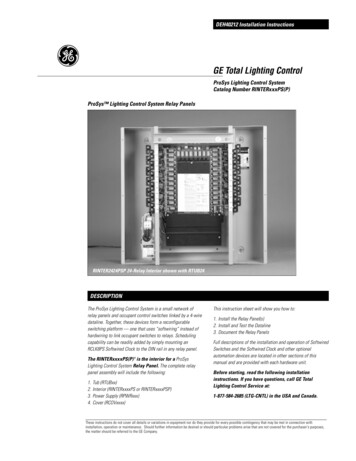
DEH40212 Installation InstructionsGE Total Lighting ControlProSys Lighting Control SystemCatalog Number RINTERxxxPS(P)ProSys Lighting Control System Relay PanelsRINTER2424PSP 24-Relay Interior shown with RTUB24DESCRIPTIONThe ProSys Lighting Control System is a small network ofrelay panels and occupant control switches linked by a 4-wiredataline. Together, these devices form a reconfigurableswitching platform — one that uses “softwiring” instead ofhardwiring to link occupant switches to relays. Schedulingcapability can be readily added by simply mounting anRCLK8PS Softwired Clock to the DIN rail in any relay panel.The RINTERxxxxPS(P) 1 is the interior for a ProSysLighting Control System Relay Panel. The complete relaypanel assembly will include the following:1.2.3.4.Tub (RTUBxx)Interior (RINTERxxxxPS or RINTERxxxxPSP)Power Supply (RPWRxxx)Cover (RCOVxxxx)This instruction sheet will show you how to:1. Install the Relay Panel(s)2. Install and Test the Dataline3. Document the Relay PanelsFull descriptions of the installation and operation of SoftwiredSwitches and the Softwired Clock and other optionalautomation devices are located in other sections of thismanual and are provided with each hardware unit.Before starting, read the following installationinstructions. If you have questions, call GE TotalLighting Control Service at:1-877-584-2685 (LTG-CNTL) in the USA and Canada.These instructions do not cover all details or variations in equipment nor do they provide for every possible contingency that may be met in connection withinstallation, operation or maintenance. Should further information be desired or should particular problems arise that are not covered for the purchaser's purposes,the matter should be referred to the GE Company.1
DEH40212 Installation InstructionsCAUTION: Make sure all power is OFF before wiring.Do not energize wiring until the unit is fully assembled.Conform to all applicable codes.RELAY PANEL INSTALLATIONSWITCHED LIGHTING CIRCUITSFigure 11.5" x 1.5" CROSSOVER WIRING CHANNEL (TOP AND BOTTOM)2" TYP.Dimensions (A x B)RINTER1212PS(P)16.0" (406mm) x 16.5" (419mm)RINTER2424PS(P)22.5" (572mm) x 24.0" (610mm)RINTER4848PS(P)36.0" (914mm) x 24.0" (610mm)RELAYSRelay Capacities (C)RINTER1212PSRINTER1212PSP12 RR7 relays12 RR9 relaysRINTER2424PSRINTER2424PSP24 RR7 relays24 RR9 relaysRINTER4848PSRINTER4848PSP48 RR7 relays48 RR9 relaysCLASS 2LOW-VOLTAGEWIRING SECTIONRELAYSACCDIN RAILCIRCUIT BREAKER PANELDIN Rail CapacitiesRINTER1212PS(P)One moduleRINTER2424PS(P)Two modulesRINTER4848PS(P)Two modules4.5" DLINE-VOLTAGE WIRING SECTIONS5" WIDEIf you have purchased the ProSys II Lighting Control System(the stand-alone system), the devices (panels, switches andclock) will be in self-install mode, which means that as soonas they are connected to the network, they are operationaland can communicate with each other.If you have purchased the ProSys LM Lighting Control Systemalong with the ProSys LM software, the devices will be insoftware-install mode. This means that in order for them tofunction on the network you must: assign network addresses to the devices and bind network variables and message tags using yournetwork management tool.Addresses and binding are necessary for the devices to function onthe network. ProSys LM users please refer to the ProSys LMSoftware User Guide for instructions on installing devices.Rough-In Tub Environment32 to 131oF (0 to 50 oC), 0 to 95% relative humidity,stationary applications MountingThe tub should be level, plumb and rigidly installed withhardware sufficient to hold 100 lbs. (48kg). For flush-mountpanels, the front flange should be flush with the finalfinished surface. For multiple panels, allow 1 4” minimumbetween panels for showbox cover clearance. Pulling WiresRoute line-voltage wiring through the 2 1 2” knockouts ineither the top or bottom of the tub. Route Class 2 lowvoltage dataline from the remote switches or other controlsthrough the 3 4” knockouts in either end.2BILLUSTRATION NOT TO SCALEInstall Interior Power SupplyAttach the power supply to the frame (bottom of 12-relayinterior and left side of 24- or 48-relay interiors) and plugthe low-voltage connector to the terminal marked “POWER”as shown in Figure 1 above. InteriorMount the interior in the tub and secure it to the studs withthe hardware provided. Make sure that all line- and lowvoltage wiring is confined to the appropriate areas.Wire Line VoltageBefore making any connections to the relays, make sure thatnone of the load circuits are shorted. Wire from the circuitbreaker through each relay’s SPST output terminals, and fromthere to the loads. Confirm that each circuit is wired to therelay specified in the drawings. Wire the power supply.Figure 2115 NEU GRDVACJ2GE Lighting ControlsRINTER2424PSshown
DEH40212 Installation InstructionsPOWER UP AND TEST RELAYS1. Apply power to the power supply only. As shown inFigure 3, to the right, press the Relay Control Button nextto each relay’s yellow plug-in termination to toggle it ON/OFF. The relay should “click” and the LED status indicatorshould change state. Confirm the operation by measuringthe continuity at the line-voltage terminations of eachrelay.2. Apply power to the relays. Being careful not to touchany line-voltage wiring, toggle each relay ON/OFF againand confirm that each relay controls the appropriate load.Figure 3TO RELAYRR7P RELAY SHOWNLED INDICATORRELAYCONTROLBUTTONDOCUMENT RELAY WIRINGRecord the circuit controlled by each relay on the RELAYSCHEDULE which was shipped with the interior. The relaysFigure 4associated with automation channels A-H are recorded later.PROSYS RELAY SCHEDULEPANEL # 01RELAY D DESCRIPTIONOPEN OFFICE - FIRST FLOOR NW"OPEN OFFICE - FIRST FLOOR NE"OPEN OFFICE - FIRST FLOOR SWSOFTWIRING A RELAY GROUP TO A CHANNELFigure 5 – Softwiring a Relay GroupHHFLASHINGRED LEDPRESSANDHOLDCHANNELPUSHBUTTON232 Select the relays tobe controlled.FLASHINGLEDHH1 Press and hold theChannel Push Buttonfor several seconds.3 Press the ChannelPush Button again.Each ProSys panel includes eight “channels” (A-H) which maybe softwired to relays within the panel. Channels are used togroup relays for common control.When a ProSys system includes an automation module(RCLK8PS Softwired Clock), we strongly recommend you turnto the installation instructions for that automation module andcomplete the documentation before softwiring anyrelays to channels.However, if automation is to be provided by an interface toanother system, or by using manual switches only, thechannels may be used simply for grouping relays. Follow theinstructions in Figure 5 to the left.Test. Press theChannel Push Buttonto toggle the groupON/OFF/ON.3
DEH40212 Installation InstructionsDATALINE INSTALLATIONGLOBAL (PANEL-TO-PANEL) DATALINEPANEL 01PANEL 02PANEL XXThe dataline connects the relay panels, switches and optionalcontrol modules. Within the 4-wire dataline are two twistedpairs: the red and black wires, carrying data; and the blue andwhite wires, providing power to the dataline switches andcontrol modules.For simplicity, we refer to a 4-wire dataline running betweena relay panel and the dataline switches as a “Local Dataline”.The relay panel provides the low-voltage power to all of theintelligent devices on that section of the dataline.The dataline running between relay panels is known as the“Global Dataline,” and it uses only the red and black datawires. The blue and white wires are not connected and shouldbe trimmed.Panel AddressingGE RLONWIREP-S4 Dataline Wire SpecificationsThe two rotary switches on each relay panel set its address,allowing the differentiation between relays in different panels. NOTE: The first panel address must be set at 01 and the othersnumbered sequentially 02, 03, and so on, between 02 and 30 asshown to the right. If the panel address is set higher than 30, thechannel LEDs in the panel will flash. Setting the panel address to 30or below will return the panel to normal operation. If a panel is set tothe same address as another panel, then the two panels will notoperate properly. The ProSys LM panels can be setup in groups of 30where the panels in a group can be numbered from 00 to 30.4Note: To ensure good communications between panels,the installer must comply with the dataline specification.GE will not warrant a system using a dataline that doesnot meet our specification. To avoid questions, use GERLONWIRE-4P (plenum rated). Do not run the datalinein conduit or wiring trays with power wires. Do notconnect the local datalines from two different panels.#18 AWG (7 strands x 26 AWG)2 independent twisted pairs – black/red, blue/whiteUnshielded copper conductors2 inch twist lay on pairs, 6 inch twist lay on cablePlenum-rated copolymer jacket, 0.230" O.D.FEP 0.010" insulation, 0.060" O.D.30 pF/foot maximum capacitance-20 C to 150 C operating temperature range17 lbs. per 500 foot reelUL rated
DEH40212 Installation InstructionsHARDWIRE LOW-VOLTAGE SWITCHES (OPTIONAL)Each of the ProSys panel’s eight channels has a single switchinput which will accept any of the dry-contact configurationsshown in Figures 6 and 7, and also provides status feedbackfor that channel.ProSys panels whose catalog numbers end in “P” also includeinputs for each relay. Like the channel inputs, these supportall of the dry-contact configurations shown.Figure 6 – Hardwired Switch InputsFigure 7 – Hardwired Switch ConfigurationsRED/BLACK JUMPERMAINTAINEDISOLATED CONTACTR B Y WBLACK/WHITE JUMPER2-WIRE MOMENTARYPUSH BUTTONR B Y WSTANDARD 3-WIREMOMENTARYR B Y WSTANDARD 3-WIREMAINTAINEDR B Y WHARDWIRED CHANNEL SWITCHESHARDWIRED RELAY SWITCHES** The ability to hardwire a 2- or 3-wireswitch directly to a relay is an option inProSys system panels. For panels with relayinputs, order interiors with catalognumbers ending in P.PANEL TESTING AND TROUBLESHOOTINGPanel TestingThe panel-to-panel dataline should be tested for continuityand isolation from ground.To test for continuity, remove the red and black dataline wiresat panel 01 and wire nut together (short the wires together).Go to the last panel in the series and measure the resistancebetween the red and black terminals. It should be less than 3ohms. Return to panel 01 and restore the red and black wiresto their associated terminals.For shorts, test from red to white and black to whiteanywhere in the low-voltage section of the panel. You shouldsee an open circuit.5
DEH40212 Installation InstructionsGE Total Lighting ControlDEH40212 BL 0700 R026GE Total Lighting Control41 Woodford Avenue, Plainville, CT 06062 2000 General Electric Company
VAC NEU GRD GE Ligh ting C on r ls RELAY PANEL INSTALLATION CAUTION: Make sure all power is OFF before wiring. . breaker through each relay's SPST output terminals, and from . 2000 General Electric Company GE Total Lighting Control DEH40212 BL 0700 R02. Title: ProSys Relay Panels Keywords: DEH40212, DEH-40212