Transcription
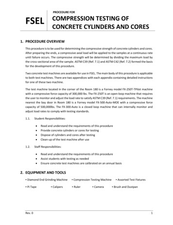
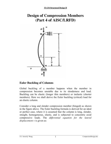
53:134 Structural Design IIDesign of Compression Members(Part 4 of AISC/LRFD)Euler Buckling of ColumnsGlobal buckling of a member happens when the member incompression becomes unstable due to its slenderness and load.Buckling can be elastic (longer thin members) or inelastic (shortermembers). Here we shall derive the Euler buckling (critical) load foran elastic column.Consider a long and slender compression member (hinged) as shownin the figure above. The Euler buckling formula is derived for an idealor perfect case, where it is assumed that the column is long, slender,straight, homogeneous, elastic, and is subjected to concentric axialcompressive loads. The differential equation for the lateraldisplacement v is given as:J.S. Arora/Q. Wang1CompresionDesign.doc
53:134 Structural Design IIEId 2vdx 2 M Pvwhere E is the modulus of elasticity, I is the moment of inertia aboutthe axis of bending in the cross section, P is the axial compressiveforce, and M is the bending moment at a distance x from support A. Ifwe consider the column to be at the point of buckling, we haved 2vdx 2 Pcrv 0EIor2v′′ k 2v 0 , where k PcrEIThis is a second-order homogeneous linear differential equation withconstant coefficients. The boundary conditions for the problem arealso homogeneous asv(0 ) 0 and v( L ) 0The solution of the differential equation isv C1 cos kx C2 sin kxThe integration constants C1 and C2 can be found by applying thefollowing geometric boundary conditions:At x 0: v 0 C1 0At x L: v 0 C2 sin kL 0The above equation indicates that either C2 0, which means nolateral displacement at all, or sin kL 0 with solutionkL π ,2π ,3π " nπTherefore, Pcr isPcr n 2π 2 EIJ.S. Arora/Q. WangL22CompresionDesign.doc
53:134 Structural Design IIVarious values of n correspond to different buckling loads. Whenn 1 , the smallest value obtained is known as critical load, bucklingload, or Euler formula:Pcr π 2 EIL2Note that the critical buckling load is independent of the strength ofthe material (say, Fy , the yield stress). This equation was obtained fora column with hinged ends. The equation can be used for columnswith other end conditions, as follows:Pcr π 2 EI(KL )2where KL is the distance between the points of zero moment, orinflection points along the length. The length KL is known as theeffective length of the column. The dimensionless coefficient K iscalled the effective length factor.Dividing the critical load Pcr by the cross-sectional area of thecolumn A, we can find the critical stress Fcr , asFcr PcrA π 2 EI π 2E( KL )2 A ( KL / r )2where r is the radius of gyration of the cross section about the axis ofbending ( I Ar 2 ) and KL/r is called the slenderness ratio of thecolumn. A thin column has small radius of gyration and a stockycolumn has large radius of gyration. The slenderness ratio determineselastic or inelastic mode of buckling failure. Columns with smallslenderness ratios are called short columns. Short columns (small KL/r) do not buckle and simply fail bymaterial yielding.J.S. Arora/Q. Wang3CompresionDesign.doc
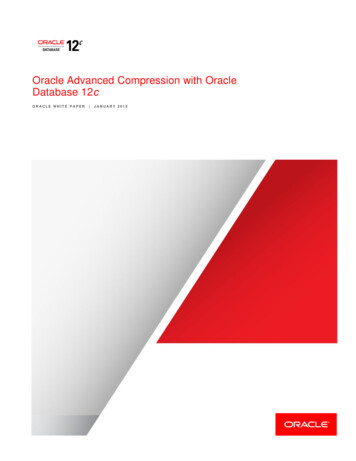
53:134 Structural Design II Long columns (large KL/r) usually fail by elastic bucklingmentioned above. Between short and long regions, the failure of the columnoccurs through inelastic buckling.The figure shows the three types of failure modes for a column.(If we define a slenderness parameter as λc2 Fy / Fcrλc )KL Fyrπ EThen the equation of the critical stress Fcr isFcr π 2E( KL / r )2 1λc2FyNote that λc 1 .Notations:J.S. Arora/Q. Wang4CompresionDesign.doc
53:134 Structural Design IIφcResistance factor for compression (0.85)AgGross cross-sectional areaFySpecified minimum yield stressPnNominal axial strength of the sectionPuEKLrRequired axial strengthModulus of elasticityEffective length factorLateral unbraced length of the memberGoverning radius of gyrationDesign Strength:φc Pn for compression members based on buckling failure mode The critical load is given asPcr π 2 EI( KL )2 π 2 EA( KL / r )2;I r2A Buckling can take place about the strong (x) axis or the weak(y) axis. Larger value for KL/r will give smaller critical load, and thuswill govern the design strength. Defineλx K x Lxrx;λy K y LyryLx unbraced length for bending about the strong axisLy unbraced length for bending about the weak axis If λ y λ x , buckling about the y axis will govern the designstrength; i.e.,J.S. Arora/Q. Wang5CompresionDesign.doc
53:134 Structural Design IIK y Lyry K x LxrxK y Ly orK x Lxrx / ryHow to Use Manual Table 4-2: Design strength in axial compression is calculated asφc Pn 0.85Fcr Ag Table contains φc Pn for various values of KyLy, assumingbuckling about y-axis. How to check buckling about x-axis:K x LxKL If y y r / r buckling is about x-axis.xy How to read φc Pn if buckling is about x-axis:K x LxUse the length as r / r in Table 4-2.xyDesign Procedure:1. Calculate the factored design loads Pu .2. From the column tables, determine the effective length KL using K LKL max K y Ly ( weak axis), x x (strong axis) rx / ry and pick a section from Table 4-2.J.S. Arora/Q. Wang6CompresionDesign.doc
53:134 Structural Design II3. Check the member thickness ratio in Table B5.1, if the member isnot slender, use LRFD Chapter E2; otherwise, use LRFDSpecifications Appendix E3 (reduction of design strength by factorQ given in Appendix B of Specifications).4. Check using Table 4-2 to 4-17: Calculate KL and enter into Table 4-2 to 4-17.Find the design strength φc Pn .Or, using the formulas given in Chapter E2:The slenderness parameter is calculated as K Lx x rxπλc max FyE,K y LyryπFy E The critic al stress is calculated as 0.658λ2c Fy Fcr 0.877 2 Fy λcJ.S. Arora/Q. Wangfor λc 1.5AISC EQ. ( E 2 2 )for λc 1.5AISC EQ. ( E 2 3 )7CompresionDesign.doc
53:134 Structural Design IIThe design strength φc Pn φc Fcr Ag 0.85Fcr AgRequired strength Design strengthPu φc PnCheck for Slenderness Ratio:Slenderness ratio (recommendation) (SPEC B7)KL / r 200Local BucklingLocal buckling is an instability due to the plates of the memberbecoming unstable. The local buckling of a member depends on itsslenderness which is defined as the width-thickness ratio (b/t ratio), bis the width of the section and t is its thickness. Steel sections areclassified as compact, noncompact or slender depending on the widththickness ratio of their elements.Compact section: is capable of developing a fully plastic stressdistribution and possess rotation capacity of approximately threebefore the onset of local buckling; i.e., local buckling is not an issue.Noncompact section: can develop the yield stress in compressionelements before local buckling occurs, but will not resist inelasticlocal buckling at strain levels required for a fully plastic stressdistribution. Local buckling can occur in the inelastic zone.Compact sections have small b/t ratio and do not buckle locally;noncompact section can buckle locally; slender sections have a largeb/t ratio. Let us define the width-thickness ration of an element of thecross-section (flange or web of WF shapes) asbtThen the members are classified as follows:λ J.S. Arora/Q. Wang8CompresionDesign.doc
53:134 Structural Design IICompact section:λ λ p for all elementsNoncompact sections:λ p λ λr .Slender:λ λr .The limiting values λp and λr for λ are given in Table B5.1 of theLRFD Secifications.The strength corresponding to any buckling mode cannot bedeveloped if the elements of the cross-section fail in local buckling.When b/t exceeds a limit λr (Table B5.1 of the LRFD Specifications),the member is classified as slender. Slender members can fail in localbuckling resulting in reduced design strength. For slender members,Appendix B of the LRFD Specifications describes the reductionfactors Q to be used for calculation of the critical stress Fcr.Basically, the design strength needs to be reduced if the member isslender. Table B5.1 of the LRFD Specifications defines the followinglimits for sections that are not slender:Unstiffened elements (flange):bf2t f λr ;h λr ;twStiffened element (web):λr 0.56 E / Fyλr 1.49 E / FyFlexural-Torsional Buckling:Thin unsymmetrical members can fail in flexural-torsional bucklingunder axial loads, such as angles, tees. Calculation of design strengthbased on the flexural-torsional buckling failure mode is described inSection E3 and Appendix E3 of the LRFD Specifications.J.S. Arora/Q. Wang9CompresionDesign.doc
How to Use Manual Table 4-2: . F . AISC EQ.( E ) F y c y cr c for 1 5 2 3 0 877 0 658 for 1 5 2 2 2 c c 2 λ λ λ λ J.S. Arora/Q. Wang 7 CompresionDesign.doc . 53:134 Structural Design II The design strength φ φ c n c cr g 0.85 P F A F A cr g Required strength Design strength φP P u c n Check for Slenderness Ratio: Slenderness ratio (recommendation) (SPEC B7) KL r / 200 .